Addi-Data MSX-E3701-DIO Parts list manual

DIN EN ISO 9001:2008 certified Edition: 02.02-11/2015
TECHNICAL
DESCRIPTION
MSX-E3701-DIO
Ethernet system for length measurement

Product information
This manual contains the technical installation and important instructions for correct commissioning
and usage, as well as production information according to the current status before printing.
The content of this manual and the technical product data may be changed without prior notice.
ADDI-DATA GmbH reserves the right to make changes to the technical data and the materials included
herein.
Warranty and liability
The user is not permitted to make changes to the product beyond the intended use, or to interfere
with the product in any other way.
ADDI-DATA shall not be liable for obvious printing and phrasing errors. In addition, ADDI DATA, if
legally permissible, shall not be liable for personal injury or damage to materials caused by improper
installation and/or commissioning of the product by the user or improper use, for example, if the
product is operated despite faulty safety and protection devices, or if notes in the operating
instructions regarding transport, storage, installation, commissioning, operation, thresholds, etc. are
not taken into consideration. Liability is further excluded if the operator changes the product or the
source code files without authorisation and/or if the operator is guilty of not monitoring the
permanent operational capability of working parts and this has led to damage.
Copyright
This manual, which is intended for the operator and its staff only, is protected by copyright.
Duplication of the information contained in the operating instructions and of any other product
information, or disclosure of this information for use by third parties, is not permitted, unless this right
has been granted by the product licence issued. Non-compliance with this could lead to civil and
criminal proceedings.
ADDI-DATA software product licence
Please read this licence carefully before using the standard software. The customer is only granted the
right to use this software if he/she agrees with the conditions of this licence.
The software must only be used to set up the ADDI-DATA products.
Reproduction of the software is forbidden (except for back-up and for exchange of faulty data
carriers). Disassembly, decompilation, decryption and reverse engineering of the software are
forbidden. This licence and the software may be transferred to a third party if this party has acquired a
product by purchase, has agreed to all the conditions in this licence contract and the original owner
does not keep any copies of the software.
Trademarks
•ADDI-DATA, APCI-1500, MSX-Box and MSX-E are registered trademarks of ADDI-DATA GmbH.
•Turbo Pascal, Delphi, Borland C, Borland C++ are registered trademarks of Borland Software
Corporation.
•Microsoft .NET, Microsoft C, Visual C++, MS-DOS, Windows XP, Windows 7, Windows 8, Windows
Server 2000, Windows Server 2003, Windows Embedded and Internet Explorer are registered
trademarks of Microsoft Corporation.
•LabVIEW, LabWindows/CVI, DASYLab, DIAdem are registered trademarks of National Instruments
Corporation.
•CompactPCI is a registered trademark of PCI Industrial Computer Manufacturers Group.
•VxWorks is a registered trademark of Wind River Systems, Inc.
•RTX is a registered trademark of IntervalZero.
•Mozilla Firefox is a registered trademark of Mozilla Foundation.
•SIMATIC S7 is a registered trademark of Siemens AG.
www.addi-data.com 2
Warning!
The following risks result from the improper implementation of the
Ethernet system and from use contrary to the regulations:
Personal injury
Damage to the Ethernet system, the PC and peripherals
Pollution of the environment.
Protect yourself, others and the environment!
Read the safety precautions (yellow leaflet) carefully!
If this leaflet is not enclosed with the documentation, please contact us
and ask for it.
Observe the instructions of this manual!
Make sure that you do not forget or skip any step!
We are not liable for damages resulting from the wrong use of the
Ethernet system.
Pay attention to the following symbols:
NOTICE!
Designates hints and other useful information.
NOTICE!
Designates a possibly dangerous situation.
If the instructions are ignored, the Ethernet system, the PC and/or
peripherals may be destroyed.
WARNING!
Designates a possibly dangerous situation.
If the instructions are ignored, the Ethernet system, the PC and/or
peripherals may be destroyed and persons may be endangered.
www.addi-data.com 3

Contents MSX-E3701-DIO
Contents
Warning! ...........................................................................................................................................3
Chapter overview.............................................................................................................................7
1Definition of application, user, handling ...........................................................................8
1.1 Definition of application......................................................................................................................8
1.1.1 Intended use..........................................................................................................................................8
1.1.2 Usage restrictions..................................................................................................................................8
1.1.3 Limits of use ..........................................................................................................................................8
1.2 Safety precautions ................................................................................................................................8
1.2.1 Current sources .....................................................................................................................................8
1.2.2 Degrees of protection ..........................................................................................................................8
1.2.3 Cables.....................................................................................................................................................9
1.2.4 Housing..................................................................................................................................................9
1.3 User ........................................................................................................................................................9
1.3.1 Qualification..........................................................................................................................................9
1.3.2 Country-specific regulations ................................................................................................................9
1.4 Handling of the Ethernet system.......................................................................................................10
1.5 Questions and updates.......................................................................................................................10
2Brief description..................................................................................................................11
2.1 Functions and features .......................................................................................................................11
2.2 Block diagram .....................................................................................................................................12
3Displacement transducers ..................................................................................................13
3.1 Inductive transducers..........................................................................................................................13
3.1.1 Half-bridge transducers......................................................................................................................13
3.1.2 LVDT transducers ................................................................................................................................14
3.2 Transducer properties.........................................................................................................................14
4Function description: Transducer inputs...........................................................................15
4.1 Pin assignment ....................................................................................................................................15
4.2 Acquisition principle ...........................................................................................................................16
4.3 Calibration...........................................................................................................................................16
4.4 Diagnostic function.............................................................................................................................25
5Function description: Digital inputs/outputs....................................................................26
5.1 Pin assignment ....................................................................................................................................26
5.2 SOAP/Modbus API ...............................................................................................................................26
5.3 Connection examples..........................................................................................................................27
6Web interface: Quick access to the MSX-E system ...........................................................28
6.1 Menu item “I/O Configuration” ........................................................................................................28
6.1.1 “Digital I/O” tab..................................................................................................................................28
6.1.2 “Transducers” tab...............................................................................................................................29
6.2 Menu item “Transducers” ..................................................................................................................29
6.2.1 “Database” tab ...................................................................................................................................29
6.2.2 “Diagnosis” tab...................................................................................................................................30
6.3 Menu item “Acquisition” ...................................................................................................................30
6.3.1 “Auto-refresh” and “Sequence” tabs ...............................................................................................30
6.3.2 “Monitor” tab .....................................................................................................................................31
6.3.3 “Help” tab ...........................................................................................................................................31
7Acquisition modes ..............................................................................................................32
7.1 Auto-refresh mode .............................................................................................................................32
7.1.1 “Channel configuration” (channel selection)...................................................................................32
7.1.2 “Transducer selection” .......................................................................................................................32
7.1.3 “Average” (average value calculation) .............................................................................................33
7.2 Sequence mode...................................................................................................................................34
7.2.1 “Channel configuration” (channel selection)...................................................................................35
www.addi-data.com 4

Contents MSX-E3701-DIO
7.2.2 “Transducer selection” .......................................................................................................................35
7.2.3 “Delay” (wait time).............................................................................................................................35
7.2.4 “Sequence measurement” (number of sequences)..........................................................................36
7.3 Common functions..............................................................................................................................38
7.3.1 “Division factor” .................................................................................................................................38
7.3.2 “Acquisition time”..............................................................................................................................38
7.3.3 Trigger configuration .........................................................................................................................38
7.3.4 “Data server frame configuration” (supplementary data)..............................................................46
7.3.5 “Data server frame format” (data format).......................................................................................47
8Technical data and limit values .........................................................................................49
8.1 Electromagnetic compatibility (EMC)................................................................................................49
8.2 Mechanical structure ..........................................................................................................................49
8.3 Versions and options ..........................................................................................................................50
8.4 Limit values..........................................................................................................................................50
8.4.1 Ethernet...............................................................................................................................................51
8.4.2 Trigger input .......................................................................................................................................51
8.4.3 Synchro input and output ..................................................................................................................52
8.4.4 Transducer inputs................................................................................................................................52
8.4.5 Sine wave generator (transducer supply) .........................................................................................53
8.4.6 Digital inputs.......................................................................................................................................54
8.4.7 Digital outputs ....................................................................................................................................54
9Appendix .............................................................................................................................55
9.1 Glossary................................................................................................................................................55
9.2 Index ....................................................................................................................................................58
10 Contact and support ...........................................................................................................59
Figures
Fig. 1-1: Correct handling ...........................................................................................................................10
Fig. 2-1: MSX-E3701-DIO: Block diagram...................................................................................................12
Fig. 3-1: Half-brige transducer ...................................................................................................................13
Fig. 3-2: LVDT transducer............................................................................................................................14
Fig. 4-1: MSX-E3701-DIO: Acquisition principle ........................................................................................16
Fig. 4-2: ConfigTools: Main window ..........................................................................................................17
Fig. 5-1: Pin assignment: Digital I/O (37-pin D-Sub male connector).......................................................26
Fig. 5-2: Connection example: Digital inputs (24 V) .................................................................................27
Fig. 5-3: Connection example: Digital outputs (24 V)...............................................................................27
Fig. 6-1: Web interface: “XT-370x-MIX” option........................................................................................28
Fig. 6-2: I/O configuration: Digital inputs..................................................................................................28
Fig. 6-3: I/O configuration: Digital outputs ...............................................................................................29
Fig. 6-4: MSX-E transducer database .........................................................................................................29
Fig. 6-5: I/O Configuration: Diagnosis........................................................................................................30
Fig. 6-6: Acquisition modes: Auto-refresh and Sequence ........................................................................30
Fig. 7-1: Auto-refresh mode: “Channel configuration” ...........................................................................32
Fig. 7-2: Auto-refresh mode: “Transducer selection”...............................................................................32
Fig. 7-3: Auto-refresh mode: “Average” ...................................................................................................33
Fig. 7-4: Auto-refresh mode: Acquisition per sequence ...........................................................................33
Fig. 7-5: Auto-refresh mode: Acquisition per channel .............................................................................34
Fig. 7-6: Sequence mode: “Channel configuration”.................................................................................35
Fig. 7-7: Sequence mode: “Transducer selection” ....................................................................................35
Fig. 7-8: Sequence mode: “Delay” .............................................................................................................35
Fig. 7-9: Delay: Mode 1 (example) .............................................................................................................36
www.addi-data.com 5

Contents MSX-E3701-DIO
www.addi-data.com 6
Fig. 7-10: Delay: Mode 2 (example) .............................................................................................................36
Fig. 7-11: Sequence mode: “Sequence measurement“ ..............................................................................36
Fig. 7-12: “Number of sequences” (example) .............................................................................................37
Fig. 7-13: “Number of data frames” (example) ..........................................................................................37
Fig. 7-14: Acquisition: Division factor ..........................................................................................................38
Fig. 7-15: Acquisition: Acquisition time .......................................................................................................38
Fig. 7-16: Acquisition: Trigger configuration ..............................................................................................38
Fig. 7-17: Hardware trigger with “One-Shot” (a) .......................................................................................41
Fig. 7-18: Hardware trigger with “One-Shot” (b).......................................................................................41
Fig. 7-19: Hardware trigger with “One-Shot” (c) .......................................................................................42
Fig. 7-20: Hardware trigger with “One-Shot” (d).......................................................................................43
Fig. 7-21: Hardware trigger with “Sequence” (a).......................................................................................43
Fig. 7-22: Hardware trigger with “Sequence” (b).......................................................................................44
Fig. 7-23: Hardware trigger with “Sequence” (c) .......................................................................................45
Fig. 7-24: Data server frame configuration (Auto-refresh mode) .............................................................46
Fig. 7-25: Data server frame configuration (Sequence mode) ...................................................................46
Fig. 7-26: Acquisition: Data server frame format........................................................................................47
Fig. 8-1: MSX-E3701-DIO: Dimensions........................................................................................................49
Fig. 8-2: MSX-E3701-DIO: View from above..............................................................................................49
Tables
Table 4-1: Pin assignment: Transducer inputs ..............................................................................................15
Table 7-1: Auto-refresh mode: Data format ................................................................................................47
Table 7-2: Sequence mode: Data format......................................................................................................48
Table 8-1: MSX-E3701-DIO: Versions.............................................................................................................50
Table 8-2: MSX-E3701-DIO: Option ...............................................................................................................50
Table 8-3: Current consumption (at 24 V) ....................................................................................................51

Chapter overview MSX-E3701-DIO
Chapter overview
In this manual, you will find the following information:
Chapter Content
1 Important information on the application, the user and on handling the MSX-E system
as well as safety precautions
2 Brief description of the MSX-E system (functions, features, block diagram)
3 Information on inductive displacement transducers
4 Function description (transducer inputs) including pin assignment
5 Function description (digital inputs/outputs) including pin assignment and connection
examples
6 Description of the function-specific pages of the MSX-E web interface
7 Description of the acquisition modes (Auto-refresh and Sequence modes)
8 List of technical data and limit values of the MSX-E system
9 Appendix with glossary and index
10 Contact and support address
www.addi-data.com 7

Definition of application, user, handling MSX-E3701-DIO
1Definition of application, user, handling
1.1 Definition of application
1.1.1 Intended use
The Ethernet system MSX-E3701-DIO for the acquisition, processing and transferring of displacement
transducer signals as well as for digital input and output is intended for the connection to a network,
which is used as electrical equipment for measurement, control and laboratory pursuant to the norm
EN 61010-1 (IEC 61010-1).
1.1.2 Usage restrictions
The Ethernet system MSX-E3701-DIO must not be used as a safety-related part (SRP).
The Ethernet system MSX-E3701-DIO must not be used for safety-related functions.
The Ethernet system MSX-E3701-DIO must not be used in potentially explosive atmospheres.
The Ethernet system MSX-E3701-DIO must not be used as electrical equipment according to the
Low Voltage Directive 2006/95/EC.
1.1.3 Limits of use
All safety information and the instructions in the manuals must be followed to ensure proper intended
use.
Uses of the Ethernet system beyond these specifications are considered as improper use.
The manufacturer is not liable for damages resulting from improper use.
The Ethernet system must remain in its anti-static packaging until it is installed.
Please do not delete the identification numbers of the Ethernet system or the warranty claim will be
invalid.
1.2 Safety precautions
1.2.1 Current sources
All connected devices must be supplied from current sources that comply with SELV according to
IEC 60950 or EN 60950; or PELV according to IEC 60204-1 or EN 60204-1.
1.2.2 Degrees of protection
NOTICE!
The protection according to the defined degree of protection
(see Chapter 8.4) is only given if the openings are protected with
adequate protection caps or connectors.
www.addi-data.com 8

Definition of application, user, handling MSX-E3701-DIO
If you are not sure, please contact us:
Phone: +49 7229 1847-0
E-mail: [email protected]
1.2.3 Cables
The cables must be installed safely against mechanical load.
1.2.4 Housing
The housing must not be opened. It may only be opened by persons who have been authorised by
ADDI-DATA.
1.3 User
1.3.1 Qualification
Only persons trained in electronics are entitled to perform the following works:
•Installation
•Commissioning
•Use
•Maintenance.
1.3.2 Country-specific regulations
Do observe the country-specific regulations regarding
•the prevention of accidents
•electrical and mechanical installations
•Electromagnetic compatibility (EMC).
www.addi-data.com 9
Definition of application, user, handling MSX-E3701-DIO
www.addi-data.com 10
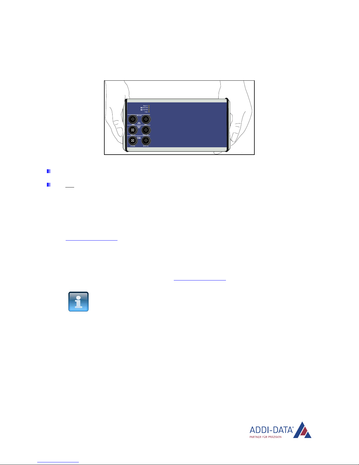
1.4 Handling of the Ethernet system
Fig. 1-1: Correct handling
Hold the Ethernet system by the bottom and the grey sides.
Do not hold the Ethernet system by the connectors!
1.5 Questions and updates
If you have any questions, you can send them to us by e-mail or call us:
E-mail: [email protected]
Phone: +49 7229 1847-0.
Manual and software download from the Internet
The latest versions of the technical manual and the standard software for the Ethernet system
MSX-E3701-DIO can be downloaded for free at: www.addi-data.com
NOTICE!
Before using the Ethernet system and in case of malfunction
during operation, check if there is an update (manual, driver,
firmware) available. Current data can be found on our website or
contact us directly.

Brief description MSX-E3701-DIO
2Brief description
2.1 Functions and features
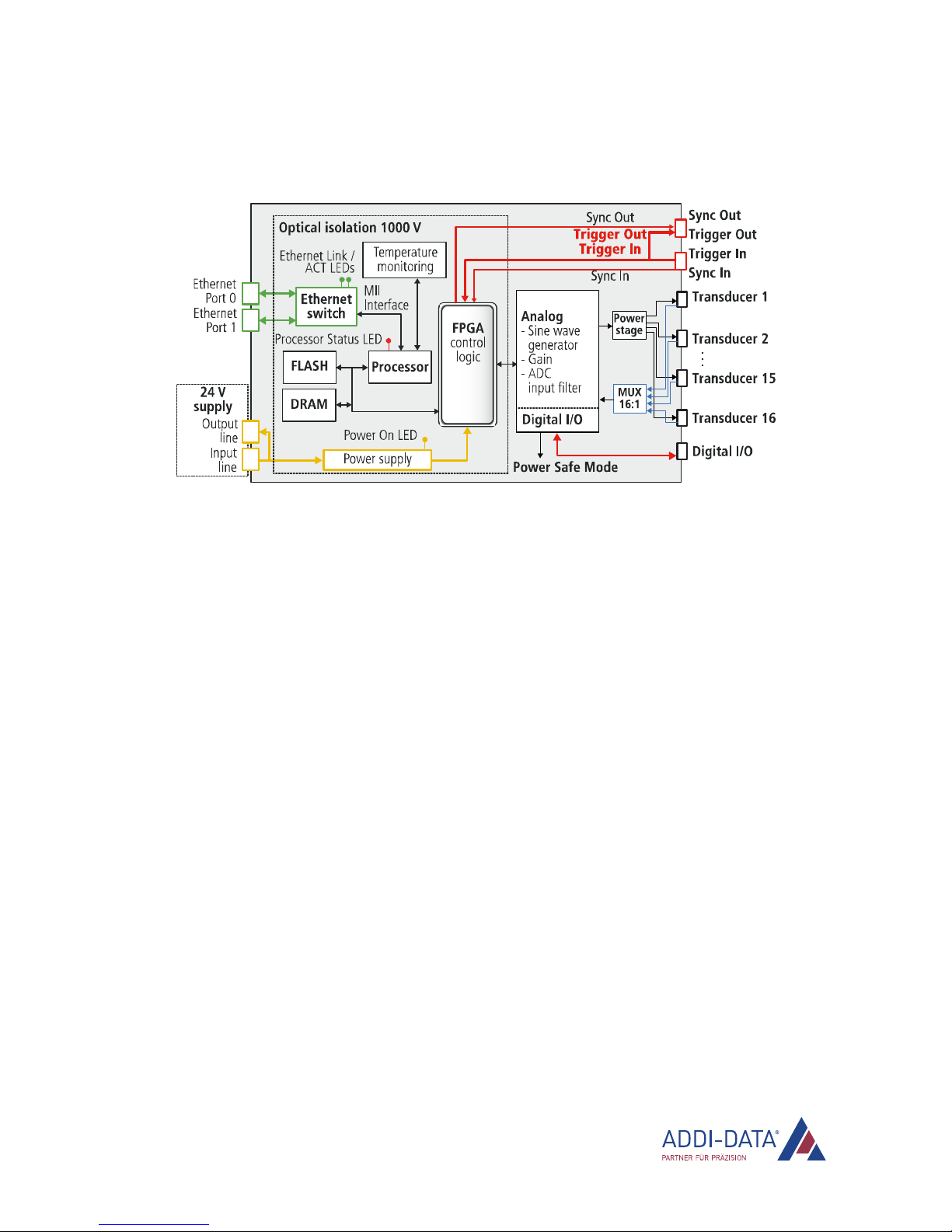
With the intelligent Ethernet system MSX-E3701-DIO, 16 HB or LVDT displacement transducers can be
acquired with 24-bit resolution. In addition, the system is equipped with 32 digital I/O (24 V).
By means of an external trigger, on multiple systems, measurement sequences can be started
simultaneously or the inputs and outputs can be updated simultaneously (synchronisation). The system
can be configured and the acquisition can be started over either the integrated web interface or SOAP
or Modbus commands. These interfaces also enable sensor data to be accessed.
Over an integrated Ethernet switch, the systems can be cascaded with other MSX-E systems. This also
applies to the voltage supply and the trigger/synchro line, which facilitates wiring between the single
systems.
The Ethernet system is mounted in a robust EMC-protected metal housing, which complies with the
degree of protection IP 65. In this way, the Ethernet system is able to cope with daily stresses and
strains such as current peaks, vibrations, dirt or extreme temperatures. Moreover, it can be used in the
operating temperature range from 0 °C to +60 °C and is equipped with numerous protective circuits.
The “Status” LED provides for a quick and easy error diagnosis.
The electronics are no longer in the computer itself but in an external housing connected to the
computer via Ethernet. As the Ethernet system is attached directly to the signal generator (measuring
point) or in direct vicinity of the sensor or actuator, the measurements and accordingly, the function of
the sensor or actuator is no longer affected by long cables. The length of the (Ethernet) connection
cable from the Ethernet system to the computer may be up to 150 m. The systems must be supplied
with external voltage (24 V).
Features:
•Acquisition of 16 inductive displacement transducers (HB, LVDT) of the same type
•XT-370x-MIX option: Acquisition of 16 HB or LVDT displacement transducers of different types
•16 digital inputs and 16 digital outputs, 24 V
•Acquisition or input/output: can be controlled by means of an external trigger (digital 24 V trigger
input)
•Web interface to configure, control and monitor the acquisition or the inputs and outputs
•Data access via SOAP or Modbus (always TCP or UDP)
•Optical isolation
•Degree of protection: IP 65
•Cascadable; synchronisation in the μs range
•Operating temperature range from 0 °C to +60 °C
www.addi-data.com 11
Brief description MSX-E3701-DIO
www.addi-data.com 12
2.2 Block diagram
Fig. 2-1: MSX-E3701-DIO: Block diagram
Displacement transducers MSX-E3701-DIO
3Displacement transducers
In this chapter, the properties of the different displacement transducers are described in more detail.
This should help you to find the right transducer for your measuring system and to identify and
prevent possible measuring errors in advance.
3.1 Inductive transducers
Inductive transducers are used for precise measurement of a defined distance. They are displacement/
voltage sensors, whose output voltage changes linearly along with the moving magnetic core (ferrite).
The magnetic core moves according to a straight line in a transformer, which consists of a central
primary coil and two external secondary coils (cylindrical windings). The power buffer provides an AC
voltage source to the primary coil. The secondary voltage changes according to the position of the
magnetic core.
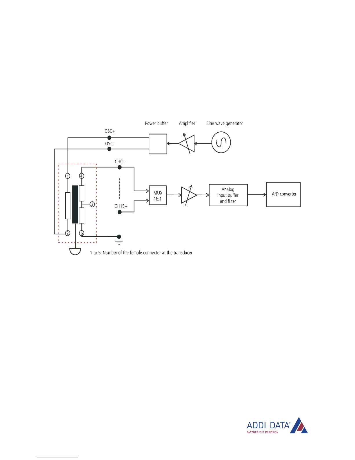
3.1.1 Half-bridge transducers
A half-bridge transducer consists of two inductive coils (windings). These are fed directly with two
sinusoidal voltage signals, i. e. a positive and a negative oscillator voltage.
A measuring bolt moves along the two coils with a ferromagnetic core. Depending on its position, this
core changes the voltages in the two coils. The measuring bolt thus functions like a variable voltage
distributor. The change in voltage at the coils results in the sinusoidal measurement signal to be
evaluated.
Fig. 3-1: Half-brige transducer
www.addi-data.com 13
Displacement transducers MSX-E3701-DIO
www.addi-data.com 14
3.1.2 LVDT transducers
An LVDT transducer features three coils: a primary coil and two secondary coils. These coils are
positioned concentrically around the mobile core and form two symmetrical transformers with respect
to the electrical zero point of the transducer.
The primary coil is fed by two sinusoidal voltage signals, i. e. a positive and a negative one, whereas
both secondary coils (switched in phase opposition) produce an electrical signal proportional to the
measured displacement.
Fig. 3-2: LVDT transducer
3.2 Transducer properties
In the ConfigTools program, in the User database, the following properties of a transducer can be
defined:
•Name
•Type
•Nominal frequency (Hz)
•Impedance (ohms)
•Nominal supply voltage Veff (Vrms)
•Sensitivity (mV/V/mm)
•Measurement range (mm).

Function description: Transducer inputs MSX-E3701-DIO
4Function description: Transducer inputs
The Ethernet system MSX-E3701-DIO has 16 single-ended inputs for inductive displacement
transducers.
4.1 Pin assignment
To each M18 female connector, one displacement transducer can be connected. The differential
transducer supply consists of OSC+ and OSC-.
NOTICE!
With the Ethernet system MSX-E3701-DIO, only one type of
transducer can be connected to one system.
Exception: The option XT-370x-MIX enables the connection of up
to 16 different HB or LVDT transducer types per system. For this,
the frequency and the input resistance of the transducers must be
equal.
Table 4-1: Pin assignment: Transducer inputs
Half-bridge LVDT
Pin No. Female connector,
5-pin, M18
Female connector,
5-pin, M18
1 OSC+ OSC+
2 GND OSC-
3 Transducer signal not connected
4 not connected Transducer signal
5 OSC- GND
OSC = oscillator voltage = supply voltage
www.addi-data.com 15
Function description: Transducer inputs MSX-E3701-DIO
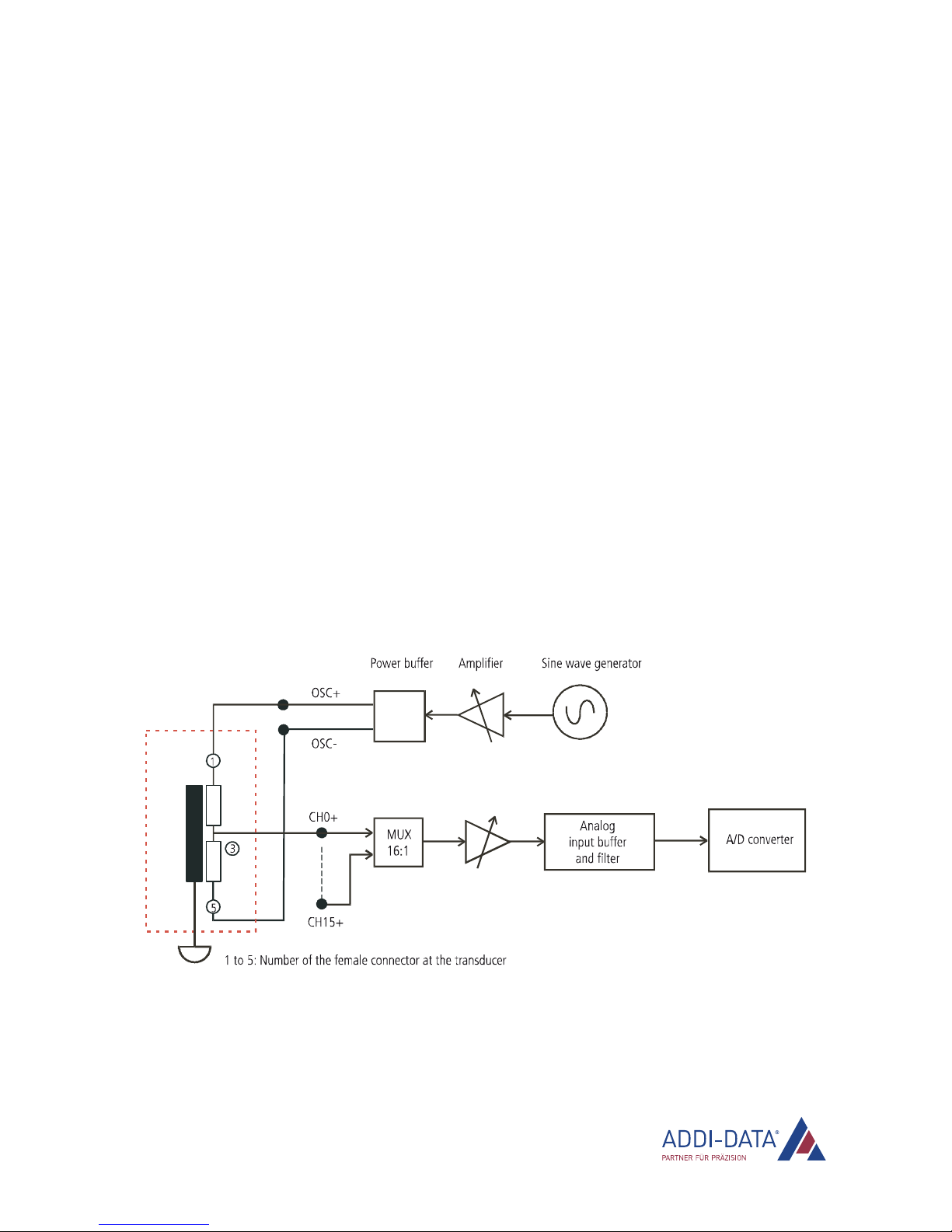
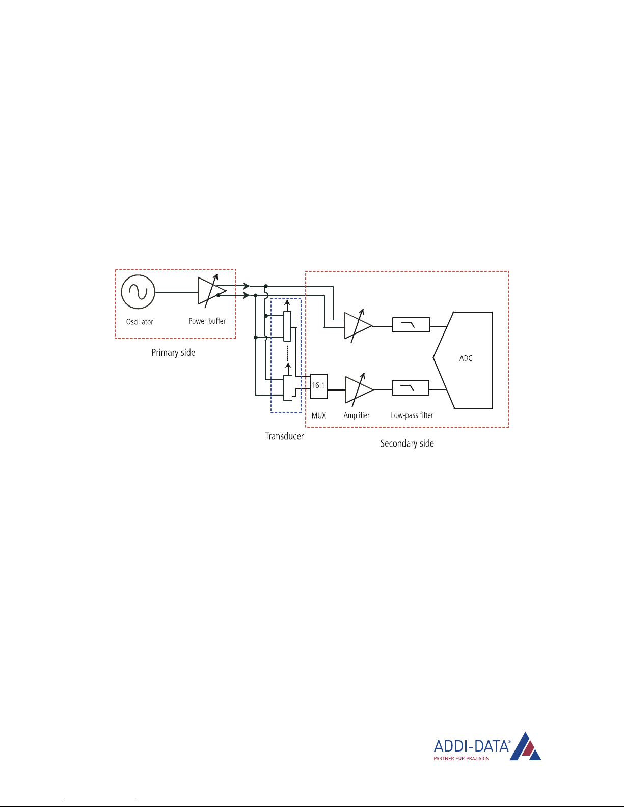
4.2 Acquisition principle
The Ethernet system MSX-E3701-DIO provides all signals required for the supply of the inductive
transducers.
By means of a sine wave generator, the primary side of the transducer is supplied. The output
frequency and the gain of the sine wave generator can be programmed through software. The
transducers are supplied via a differential power buffer.
The incoming measurement signals are led over a multiplexer (16:1).
The measurement signal passes through a software-programmable amplifier. Then the signal is led
over an analog low-pass filter and acquired by a 24-bit ADC.
Parallel to the measurement signal, the supply signal of the transducer is monitored via a second input
at the ADC.
Fig. 4-1: MSX-E3701-DIO: Acquisition principle
4.3 Calibration
The gain and the offset error of the MSX-E3701-DIO can be corrected by means of the software tool
ConfigTools (see PDF link “General manual MSX-Exxxx”). When the MSX-E system is booting up, the
calibration values are read from the flash and uploaded to the system.
www.addi-data.com 16
Function description: Transducer inputs MSX-E3701-DIO
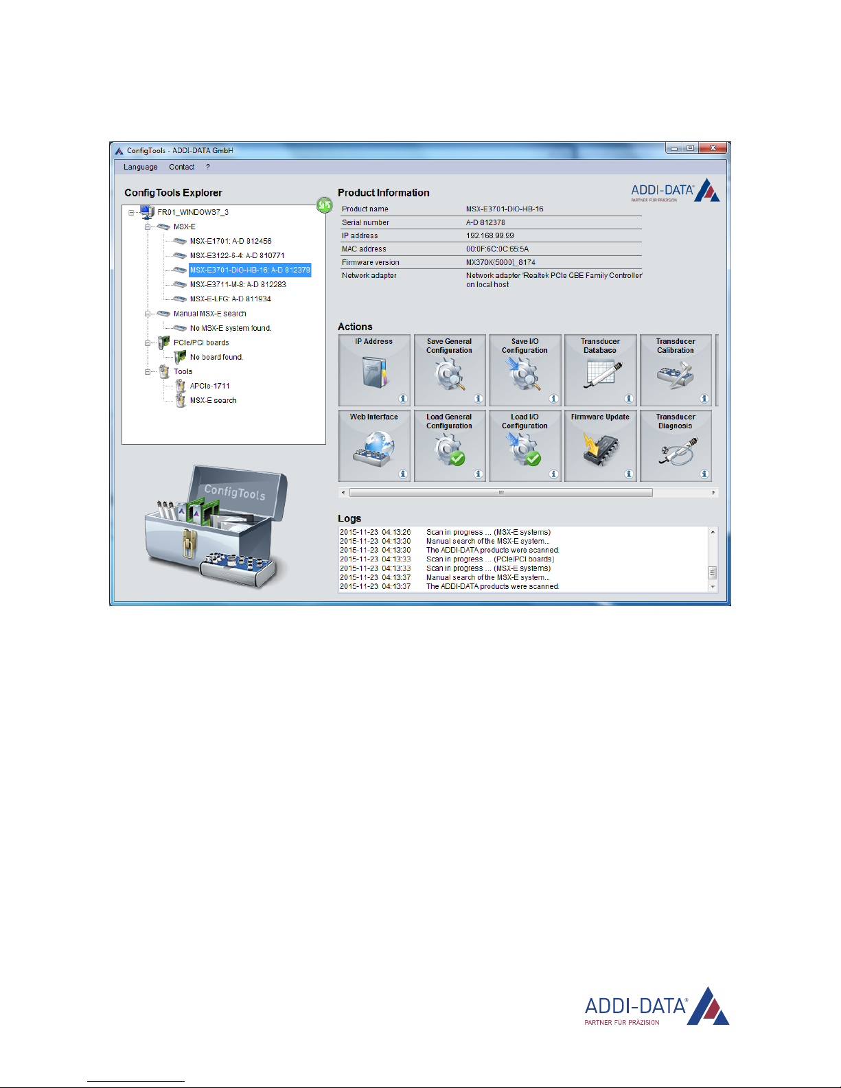
Fig. 4-2: ConfigTools: Main window
As already mentioned in Chapter 4.1, transducers of different types can be connected to the system
MSX-E3701-DIO if you use the XT-370x-MIX option. The calibration of the transducers is carried out
in one run then.
A sample for the calibration of an MSX-E3701-DIO (also with the XT-370x-MIX option) is included in
delivery of the respective system.
On the following pages, the calibration of three Solartron LVDT transducers with different measuring
ranges and sensitivity is described:
1. In the ConfigTools main window, click on the action button “Transducer Calibration”
(see Fig. 5-2).
www.addi-data.com 17
Function description: Transducer inputs MSX-E3701-DIO
www.addi-data.com 18
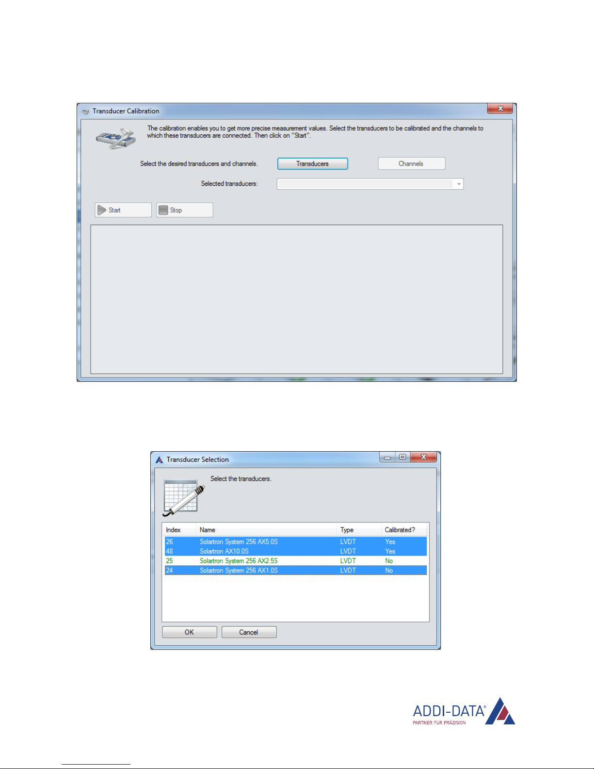
The following window is displayed:
2. Click on the “Transducers” button.
In the following window, the transducer types of the MSX-E database (action button “Transducer
Database”) are listed.
3. Select the transducers to be calibrated and click on “OK”.

Function description: Transducer inputs MSX-E3701-DIO
www.addi-data.com 19
4. Click on the “Channels” button.
the following window, via the button “Current Configuration (Recent Calibration)”, theIn
configuration used last for a calibration can be displayed.
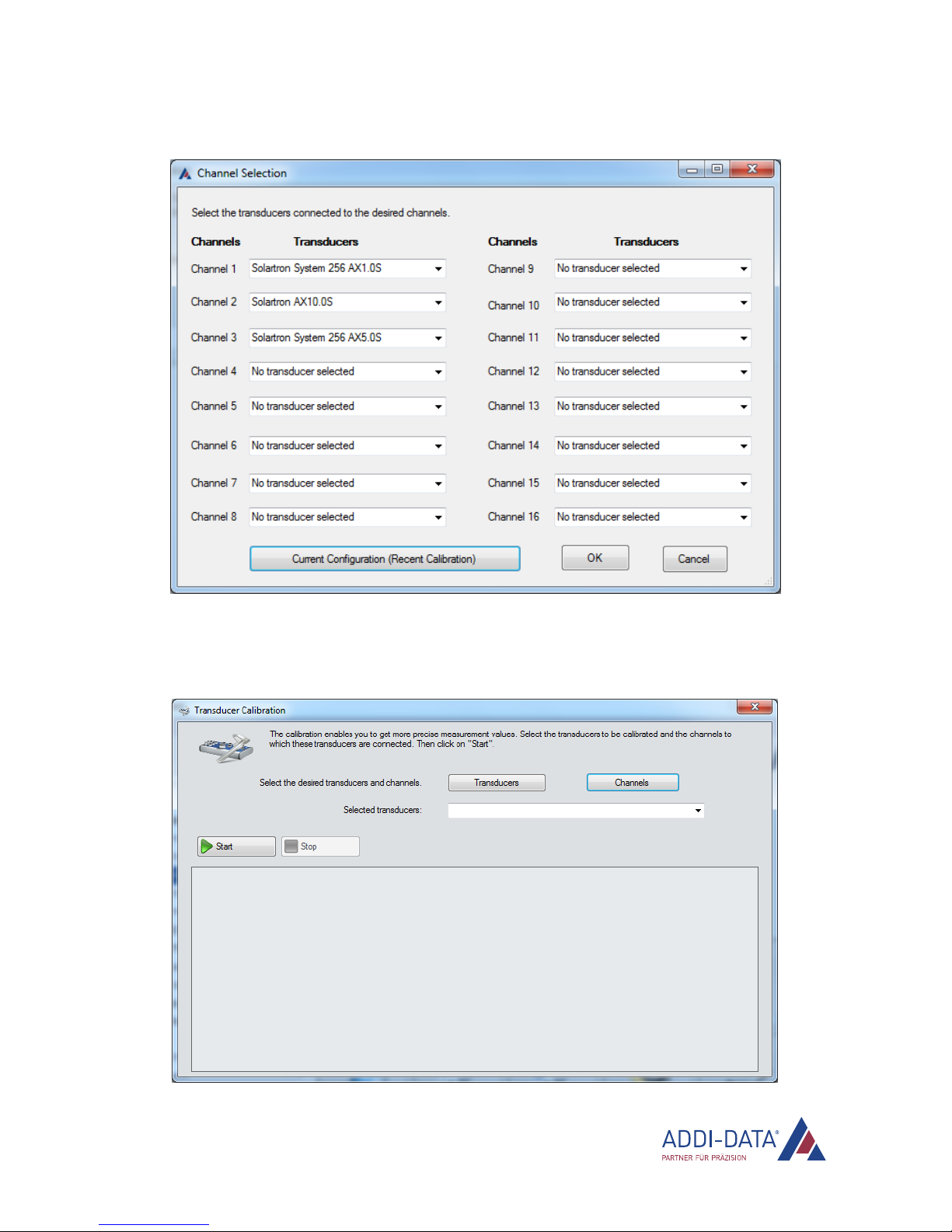
Function description: Transducer inputs MSX-E3701-DIO
www.addi-data.com 20
5. Assign the transducers to be calibrated to the corresponding channels and click on “OK”.
Assigning the transducers to the channels is also possible with the software function
“MX370x__SetMixTransducerList”.
6. Click on “Start” to start the calibration.
Other manuals for MSX-E3701-DIO
1
Table of contents
Other Addi-Data Measuring Instrument manuals

Addi-Data
Addi-Data MSX-E1701 Original operating instructions

Addi-Data
Addi-Data MSX-E3711 Original operating instructions

Addi-Data
Addi-Data MSX-E3701 Original operating instructions

Addi-Data
Addi-Data MSX-E3701-DIO Original operating instructions

Addi-Data
Addi-Data MSX-E3311 Original operating instructions
Popular Measuring Instrument manuals by other brands


Keithley
Keithley 6517A user manual

OHAUS
OHAUS MB95 instruction manual

RST Instruments
RST Instruments Digital ThermArray System installation guide

Siargo
Siargo FS6100 manual

Leuze electronic
Leuze electronic AMS 307i Series operating instructions

Hanna Instruments
Hanna Instruments HI 8043 instruction manual


