Addi-Data APCIe-7300 Parts list manual

DIN EN ISO 9001:2015 certified Edition: 02.06-09/2019
Technical Description
APCIe-7300, APCIe-7420, APCIe-7500 and APCIe-7800
1-port, 2-port, 4-port and 8-port serial interface

Product information
This manual contains the technical installation and important instructions for correct commissioning
and usage, as well as production information according to the current state before printing.
The content of this manual and the technical product data may be changed without prior notice.
ADDI-DATA GmbH reserves the right to make changes to the technical data and the materials included
herein.
Warranty and liability
The user is not authorised to make changes to the product beyond the intended use, or to interfere
with the product in any other way.
ADDI-DATA shall not be liable for obvious printing and phrasing errors.
In addition, ADDI DATA, if legally permissible, shall not be liable for personal injury or damage to
materials caused by improper installation and/or commissioning of the product by the user or improper
use; for example, if the product is operated despite faulty safety and protection devices, or if notes in
the operating instructions regarding transport, storage, installation, commissioning, operation, limit
values, etc. are not taken into consideration.
Liability is further excluded if the operator changes the product or the source code files without
authorisation and/or if the operator is guilty of not monitoring the permanent operational capability
of working parts and this has led to damage.
Copyright
This manual, which is intended for the operator and its staff only, is protected by copyright.
Duplication of the information contained in the operating instructions and of any other product
information, or disclosure of this information for use by third parties, is not permitted, unless this right
has been granted by the product licence issued. Non-compliance with this could lead to civil and
criminal proceedings.
ADDI-DATA software product licence
Please read this licence carefully before using the standard software! The customer is only granted the
right to use this software if he/she agrees with the conditions of this licence.
The software may only be used to set up the ADDI-DATA products.
Reproduction of the software is forbidden (except for back-up and for exchange of faulty data
carriers). Disassembly, decompilation, decryption and reverse engineering of the software are
forbidden. This licence and the software may be transferred to a third party if this party has acquired a
product by purchase, has agreed to all the conditions in this licence contract and the original owner
does not keep any copies of the software.
Trademarks
•ADDI-DATA, APCI-1500, MSX-Box and MSX-E are registered trademarks of ADDI-DATA GmbH.
•Turbo Pascal, Delphi, Borland C, Borland C++ are registered trademarks of Borland Software
Corporation.
•Microsoft .NET, Microsoft C, Visual C++, MS-DOS, Windows XP, Windows 7, Windows 10,
Windows Server 2000, Windows Server 2003, Windows Embedded and Internet Explorer are
registered trademarks of Microsoft Corporation.
•Linux is a registered trademark of Linus Torvalds.
•LabVIEW, LabWindows/CVI, DASYLab, DIAdem are registered trademarks of National Instruments
Corporation.
•CompactPCI is a registered trademark of PCI Industrial Computer Manufacturers Group.
•VxWorks is a registered trademark of Wind River Systems, Inc.
•RTX is a registered trademark of IntervalZero.
www.addi-data.com 2

Warning!
The following risks result from the improper implementation of the
board and from use contrary to the regulations:
Personal injury
Damage to the board, the PC and peripherals
Pollution of the environment.
Protect yourself, others and the environment!
Read the safety precautions (yellow leaflet) carefully!
If this leaflet is not enclosed with the documentation, please contact us
and ask for it.
Observe the instructions of this manual!
Make sure that you do not forget or skip any step!
We are not liable for damages resulting from the wrong use of the board.
Pay attention to the following symbols:
NOTICE!
Designates hints and other useful information.
NOTICE!
Designates a possibly dangerous situation.
If the instructions are ignored, the board, the PC and/or
peripherals may be destroyed.
WARNING!
Designates a possibly dangerous situation.
If the instructions are ignored, the board, the PC and/or
peripherals may be destroyed and persons may be endangered.
www.addi-data.com 3

Contents APCIe-7xx0
Contents
Warning! ...................................................................................................................................... 3
Chapter overview........................................................................................................................ 6
1Definition of application, user, handling ...................................................................... 7
1.1Definition of application.................................................................................................................7
1.1.1Intended use.....................................................................................................................................7
1.1.2Usage restrictions.............................................................................................................................7
1.1.3Limits of use .....................................................................................................................................7
1.2User ...................................................................................................................................................7
1.2.1Qualification.....................................................................................................................................7
1.2.2Country-specific regulations ...........................................................................................................8
1.3Handling of the board.....................................................................................................................8
1.4Questions and updates....................................................................................................................8
2Brief description............................................................................................................... 9
3Insertion and installation of the board ....................................................................... 11
3.1Insertion of the APCIe board ........................................................................................................11
3.1.1Opening the PC ..............................................................................................................................11
3.1.2Selecting a slot ...............................................................................................................................11
3.1.3Replacing the SI modules ..............................................................................................................12
3.1.4Inserting the board........................................................................................................................13
3.1.5Closing the PC ................................................................................................................................13
3.2Connecting the accessories ...........................................................................................................14
3.2.1Pin assignment ...............................................................................................................................14
3.2.2Connection cable ST075 (APCIe-7500)..........................................................................................20
3.2.3Connection cables ST074 (APCIe-7500) and ST7825 (APCIe-7800)..............................................20
3.2.4Connection cable ST7809 (APCIe-7800)........................................................................................21
3.3Connection examples.....................................................................................................................21
3.3.1RS232 ..............................................................................................................................................21
3.3.2RS422 ..............................................................................................................................................21
3.3.3RS485 ..............................................................................................................................................22
3.3.4TTY (20 mA current loop)..............................................................................................................23
3.4Driver installation ..........................................................................................................................24
3.5Board configuration ......................................................................................................................25
3.6Board test .......................................................................................................................................28
3.6.1Connecting the short-circuit plug.................................................................................................28
3.6.2Test program “MTTTY” .................................................................................................................29
4Function description ...................................................................................................... 32
4.1Block diagrams ...............................................................................................................................32
5Return or disposal.......................................................................................................... 35
5.1Return .............................................................................................................................................35
5.2Disposal of ADDI-DATA waste equipment...................................................................................36
6Technical data and limit values .................................................................................... 37
6.1Electromagnetic compatibility (EMC)...........................................................................................37
6.2Mechanical structure .....................................................................................................................37
6.3Versions ..........................................................................................................................................38
6.4Limit values.....................................................................................................................................38
6.4.1RS232 ..............................................................................................................................................39
6.4.2RS422, RS485 ..................................................................................................................................39
6.4.3TTY 20 mA constant current loop (current Loop, SITTY) ............................................................40
7Appendix ........................................................................................................................ 41
7.1Glossary...........................................................................................................................................41
7.2Index ...............................................................................................................................................43
8...................................................................................................... 44Contact and support
www.addi-data.com 4

Contents APCIe-7xx0
www.addi-data.com 5
Figures
Fig. 1-1:Correct handling ........................................................................................................................8
Fig. 3-1:PCI Express slot types ...............................................................................................................11
Fig. 3-2:Removing an SI module...........................................................................................................12
Fig. 3-3:Fitting an SI module ................................................................................................................12
Fig. 3-4:Slot: Insert the board...............................................................................................................13
Fig. 3-5:PC housing: Fasten the board .................................................................................................13
Fig. 3-6:APCIe-7500: 37-pin D-Sub male connector ............................................................................14
Fig. 3-7:APCIe-7300, APCIe-7420, APCIe-7500/4C and breakout cables: 9-pin D-Sub connector.....16
Fig. 3-8:APCIe-7800: 78-pin D-Sub female connector.........................................................................17
Fig. 3-9:APCIe-7500/4C, APCIe-7800 and breakout cables: 25-pin D-Sub male connector...............20
Fig. 3-10:RS232 wiring.............................................................................................................................21
Fig. 3-11:RS422 wiring.............................................................................................................................21
Fig. 3-12:RS422 with RTS/CTS signals as RS422 signals..........................................................................22
Fig. 3-13:RS485 wiring.............................................................................................................................22
Fig. 3-14:Active transmission / active reception ....................................................................................23
Fig. 3-15:Active transmission / passive reception ..................................................................................23
Fig. 3-16:Passive transmission / active reception...................................................................................24
Fig. 3-17:Passive transmission / passive reception.................................................................................24
Fig. 3-18:Device Manager .......................................................................................................................25
Fig. 3-19:FIFOs..........................................................................................................................................25
Fig. 3-20:Settings example: RS485..........................................................................................................26
Fig. 3-21:Settings example: TTY (20 mA current loop).........................................................................27
Fig. 3-22:Connection of the short-circuit plug (RS232).........................................................................28
Fig. 3-23:Connection of the short-circuit plug (RS422).........................................................................28
Fig. 3-24:Connection of the short-circuit plug (TTY) – active transmission / passive reception.........29
Fig. 3-25:Connection of the short-circuit plug (TTY) – passive transmission / active reception.........29
Fig. 3-26:MTTTY main window ..............................................................................................................30
Fig. 3-27:“Flow Control Settings” window............................................................................................31
Fig. 4-1:APCIe-7300: Block diagram .....................................................................................................32
Fig. 4-2:APCIe-7420: Block diagram .....................................................................................................32
Fig. 4-3:APCIe-7500: Block diagram .....................................................................................................33
Fig. 4-4:APCIe-7500/4C : Block diagram...............................................................................................33
Fig. 4-5:APCIe-7800: Block diagram .....................................................................................................34
Fig. 5-1:Serial number...........................................................................................................................35
Fig. 5-2:Disposal: Labelling ...................................................................................................................36
Fig. 6-1:APCIe-7xx0: Dimensions ..........................................................................................................37
Tables
Table 2-1: Number of serial interfaces.......................................................................................................9
Table 2-2: Plug-in modules and their transmission standards................................................................10
Table 3-1: APCIe-7500: Pin assignment....................................................................................................15
Table 3-2: APCIe-7300, APCIe-7420, APCIe-7500/4C and breakout cables: Pin assignment .................16
Table 3-3: APCIe-7800: Pin assignment....................................................................................................17
Table 3-4: APCIe-7500, APCIe-7800 and breakout cables: Pin assignment............................................20
Table 6-1: Versions ....................................................................................................................................38
Table 6-2: Current consumption (boards)................................................................................................38
Table 6-3: Current consumption (SI modules) .........................................................................................39

Chapter overview APCIe-7xx0
Chapter overview
In this manual, you will find the following information:
Chapter Content
1 Important information on the application, the user and on handling the board
2 Brief description of the board (features, cables, transmission standards)
3 Detailed information on the insertion of the board, connection of the accessories
(including pin assignment) and driver installation
Tip: Print out this chapter to have help at hand for inserting and installing the board.
4 Block diagrams of the boards
5 Procedure for returning (repairing, etc.) or disposing of the board
6 List of technical data and limit values of the board
7 Appendix with glossary and index
8 Contact and support address
www.addi-data.com 6

Definition of application, user, handling APCIe-7xx0
www.addi-data.com 7
1Definition of application, user, handling
1.1 Definition of application
1.1.1 Intended use
The APCIe-7xx01board must be inserted in a personal computer (PC) with PCI Express slots which is
used as electrical equipment for measurement, control and laboratory pursuant to the standard
EN 61010-1 (IEC 61010-1).
The used personal computer (PC) must fulfil the requirements of IEC 60950-1 or EN 60950-1 and
EN 55022 or IEC/CISPR 22 and EN 55024 or IEC/CISPR 24.
The use of the board APCIe-7xx0 in combination with external screw terminal panels requires correct
installation according to the series IEC 61439 or EN 61439 (Low-voltage switchgear and controlgear
assemblies).
1.1.2 Usage restrictions
The APCIe-7xx0 board must not be used as a safety-related part (SRP).
The board must not be used for safety-related functions, for example for emergency stop functions.
The APCIe-7xx0 board must not be used in potentially explosive atmospheres.
The APCIe-7xx0 board must not be used as electrical equipment according to the Low Voltage
Directive 2014/35/EU.
1.1.3 Limits of use
All safety information and the instructions in the manual must be followed to ensure proper intended
use.
Uses of the board beyond these specifications are considered as improper use. The manufacturer is not
liable for damages resulting from improper use.
The board must remain in its anti-static packaging until it is installed.
Please do not delete the identification numbers of the board or the warranty claim will be invalid.
1.2 User
1.2.1 Qualification
Only persons trained in electronics are entitled to perform the following works:
•Installation
•Commissioning
•Use
•Maintenance.
1APCIe-7xx0 =APCIe-7300, APCIe-7420, APCIe-7500 and APCIe-7800

Definition of application, user, handling APCIe-7xx0
www.addi-data.com 8
1.2.2 Country-specific regulations
Do observe the country-specific regulations regarding
•the prevention of accidents
•electrical and mechanical installations
•Electromagnetic compatibility (EMC).
1.3 Handling of the board
Fig. 1-1: Correct handling
Hold the board cautiously at the outer end and at the slot bracket.
Do not touch the surface of the board!
1.4 Questions and updates
If you have any questions, do not hesitate to call us or to send us an e-mail:
Phone: +49 7229 1847-0
E-mail: [email protected]
Manual and software download from the Internet
The latest versions of the technical manual and the standard software for the APCIe-7xx0 board can
be downloaded for free at: www.addi-data.com.
NOTICE!
Before using the board and in case of malfunction during
operation, check if there is an update (manual, driver) available.
Current data can be found on our website or contact us directly.

Brief description APCIe-7xx0
2Brief description
The boards APCIe-7300, APCIe-7420, APCIe-7500 and APCIe-7800 provide industrial PCs with one,
two, four or eight asynchronous serial interfaces for the communication with external devices.
The configuration of these communication boards is determined by SI modules, which are
automatically detected by the boards.
Via the SI modules, the serial interfaces can be fitted with the following transmission standards: RS232,
RS422, RS485 and TTY (with or without optical isolation). The SI modules with optical isolation offer
protection of up to 1000 V for harsh environments and prevent ground loops. The input/output lines
are protected against short-circuits, rapid transients, electrostatic discharges and high-frequency EMI.
The serial interfaces are supported by a 128-byte FIFO for data transmission and reception and
guarantee reliable operations with high data rates.
Features:
•Transmission standards: RS232, RS422, RS485, TTY (20 mA current loop); free configuration for each
interface through SI modules
•With/without optical isolation (1000 V)
•FIFO buffer (128-byte) for each interface
•UART-compatible with: 16C450, 16C550, 16C654, 16C750 and 16C950
Table 2-1: Number of serial interfaces
Board Serial interfaces
APCIe-7300 1
APCIe-7420 2
APCIe-7500
APCIe-7500/4C
4
APCIe-7800 8
Cables
In terms of electromagnetic compatibility (EMC), the connection cables have the following properties:
•Metallised connector housing
•Shielded cable
•Cable shield folded back over insulation and firmly screwed on both sides to the connector
housing.
www.addi-data.com 9

Brief description APCIe-7xx0
www.addi-data.com 10
Transmission standards
The transmission standard of the respective serial interface depends on the fitted SI module.
Table 2-2: Plug-in modules and their transmission standards
Plug-in
module1
Transmission
standard
Maximum
Baud rate
Optical
isolation
Interface
setting
Distance
between
transmitter
and receiver2
SI232 -
SI232-G
RS232 1 MBaud
1 kV
- 30 m
SI422 -
SI422-G
SI422-PEP
(RTS/CTS
as RS422)
RS422 1 MBaud
1 kV
- 1.2 km
SI485
-
Automatic
transmitter
control
SI485-G RS485 1 MBaud
1 kV
Automatic
transmitter
control
1.2 km
SITTY TTY (20 mA
current loop) 19.2 kBaud 1 kV
Standby current
on transmit and
receive channel
1 km
If the APCIe-7xx0 board is operated at the same time with modules that are optically isolated and
modules that are not optically isolated, the creeping distance of 3.2 mm applies only for the modules
that are optically isolated.
1Plug-in module SIxxx-G: The -G suffix stands for optical isolation. The SITTY module is always optically isolated.
2The indicated maximum lengths apply to normal interface cables (shielded control lead, 0.14 mm²). The length is also limited
by the number of users, line capacity, impedance and transfer rate.

Insertion and installation of the board APCIe-7xx0
3Insertion and installation of the board
3.1 Insertion of the APCIe board
Risk of injury!
Please follow the safety precautions! An improper handling of the
board may cause property damage and injury.
3.1.1 Opening the PC
Switch off the PC and all the units connected to it.
Pull the PC mains plug from the socket.
Open the PC as described in the manual of the PC manufacturer.
3.1.2 Selecting a slot
Select a free 1-lane (x1), 4-lane (x4), 8-lane (x8) or 16-lane (x16) PCI Express slot for the board.
Fig. 3-1: PCI Express slot types
Unscrew the back cover from the selected slot. For this, follow the operating instructions provided
by the PC manufacturer!
Keep the back cover in a safe place. You will need it if you remove the board.
Provide for potential equalisation.
Take the board out of its protective packaging.
www.addi-data.com 11
Insertion and installation of the board APCIe-7xx0
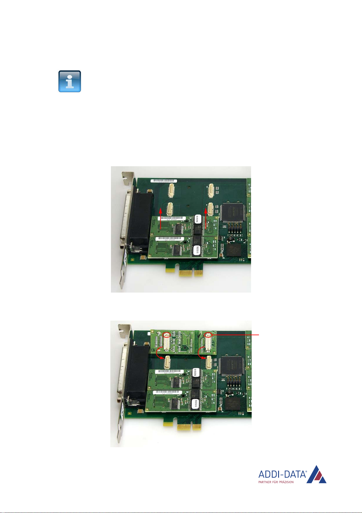
3.1.3 Replacing the SI modules
NOTICE!
If an SI module has to be replaced, we recommend you to send the
board back to us.
If you would like to replace the SI module yourself:
- Respect the combination options according to the intended use!
- Follow the safety precautions!
- Remove/fit the SI module carefully according to the following
figures!
Fig. 3-2: Removing an SI module
Fig. 3-3: Fitting an SI module
Wrong mounting
protection
www.addi-data.com 12
Insertion and installation of the board APCIe-7xx0
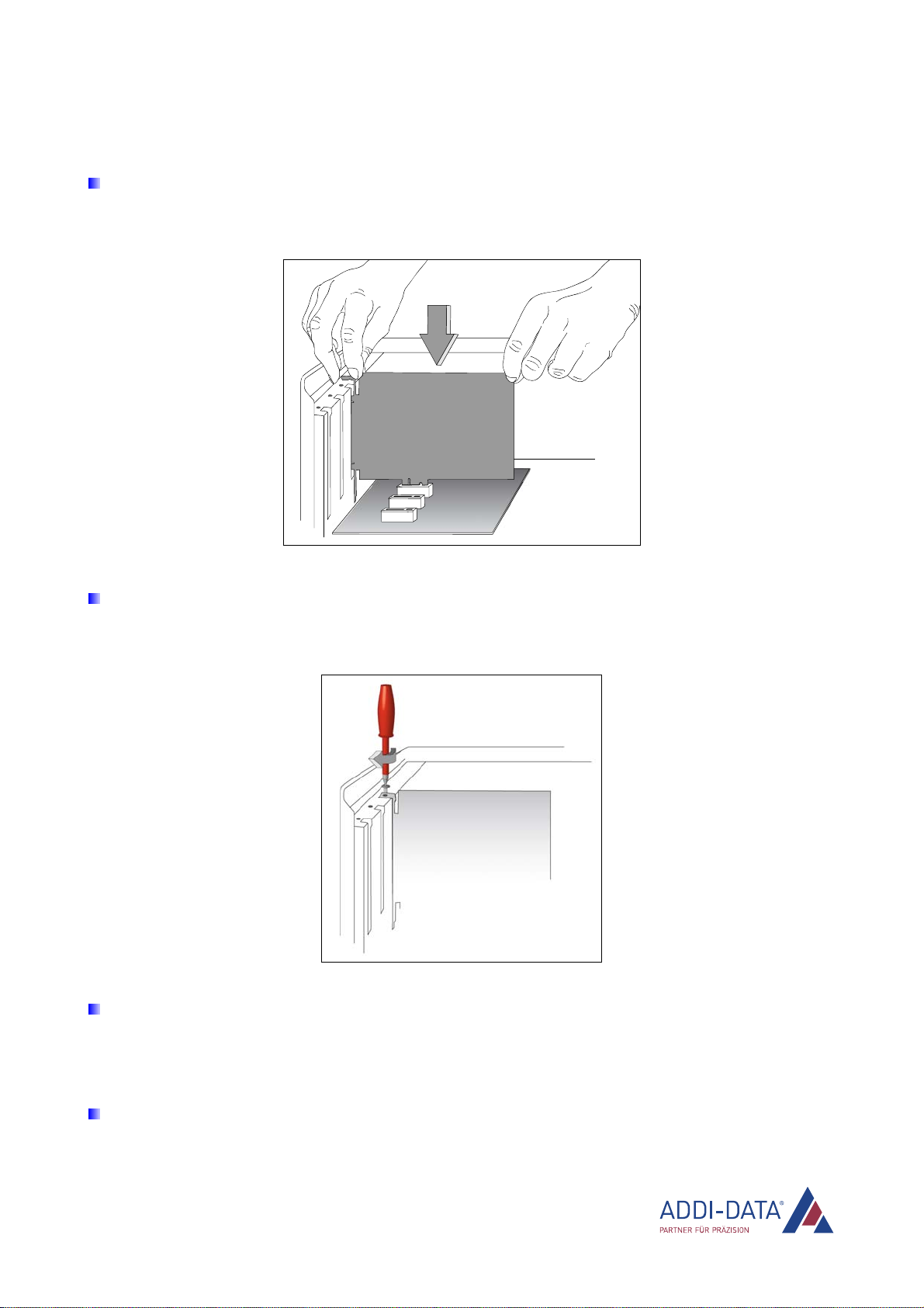
3.1.4 Inserting the board
Insert the board vertically from above into the selected slot.
Fig. 3-4: Slot: Insert the board
Fasten the board to the rear of the PC housing using the screw which held the back cover in place.
Fig. 3-5: PC housing: Fasten the board
Tighten all loose screws.
3.1.5 Closing the PC
Close the PC as described in the manual of the PC manufacturer.
www.addi-data.com 13
Insertion and installation of the board APCIe-7xx0
3.2 Connecting the accessories
NOTICE!
Interference is propagated and spread via the connection cable.
An incorrect cable could therefore jeopardise the operating and
functional safety of your system.
Use our standard connection cable.
When installing the connection cable, ensure that it is placed a sufficient distance away from
sensitive analog signals and that the distance from potential sources of interference such as
frequency inverters, mains supplies, etc. is as large as possible.
3.2.1 Pin assignment
1) APCIe-7500
Fig. 3-6: APCIe-7500: 37-pin D-Sub male connector
www.addi-data.com 14

Insertion and installation of the board APCIe-7xx0
Table 3-1: APCIe-7500: Pin assignment
Pin Interface
RS232
RS422 RS422-PEP RS485 TTY
33 DCD TA(Tx+) TA(Tx+) TCollector (Tx+)
34 Rx TB(Tx-) TB(Tx-) TEmitter (Tx-)
35 Tx RA(Rx+) RA(Rx+) Tx/Rx+ DAnode (Rx+)
36 DTR RTermination IB (CTS-) RTermination
37 GND GND GND GND GND
15 DSR 100 ΩIA(CTS+) 120 Ω
16 RTS CB(RTS-) TSource
17 CTS CA(RTS+) RSource
18
UART 0
RI RB(Rx-) RB(Rx-) Tx/Rx- DCathode (Rx-)
10 DCD TA(Tx+) TA(Tx+) TCollector (Tx+)
11 Rx TB(Tx-) TB(Tx-) TEmitter (Tx-)
12 Tx RA(Rx+) RA(Rx+) Tx/Rx+ DAnode (Rx+)
13 DTR RTermination I
B (CTS-) RTermination
14 GND GND GND GND GND
29 DSR
100 ΩIA(CTS+) 120 Ω
30 RTS CB(RTS-) TSource
31 CTS CA(RTS+) RSource
32
UART 1
RI RB(Rx-) RB(Rx-) Tx/Rx- DCathode (Rx-)
24 DCD TA(Tx+) TA(Tx+) TCollector (Tx+)
25 Rx TB(Tx-) TB(Tx-) TEmitter (Tx-)
26 Tx RA(Rx+) RA(Rx+) Tx/Rx+ DAnode (Rx+)
27 DTR RTermination IB (CTS-) RTermination
28 GND GND GND GND GND
6 DSR 100 ΩIA(CTS+) 120 Ω
7 RTS CB(RTS-) TSource
8 CTS CA(RTS+) RSource
9
UART 2
RI RB(Rx-) RB(Rx-) Tx/Rx- DCathode (Rx-)
1 DCD TA(Tx+) TA(Tx+) TCollector (Tx+)
2 Rx TB(Tx-) TB(Tx-) TEmitter (Tx-)
3
UART 3
Tx RA(Rx+) RA(Rx+) Tx/Rx+ DAnode (Rx+)
www.addi-data.com 15

Insertion and installation of the board APCIe-7xx0
Pin Interface
RS232
RS422 RS422-PEP RS485 TTY
4 DTR RTermination I
B (CTS-) RTermination
5 GND GND GND GND GND
20 DSR
100 ΩIA(CTS+) 120 Ω
21 RTS CB(RTS-) TSource
22 CTS CA(RTS+) RSource
23
UART 3
RI RB(Rx-) RB(Rx-) Tx/Rx- DCathode (Rx-)
A cable connection between the resistor (RS422/RS485) and RTermination activates the termination resistor.
2) APCIe-7300, APCIe-7420, APCIe-7500/4C and breakout cables
Fig. 3-7: APCIe-7300, APCIe-7420, APCIe-7500/4C and breakout cables: 9-pin D-Sub connector
Table 3-2: APCIe-7300, APCIe-7420, APCIe-7500/4C and breakout cables: Pin assignment
Pin RS232
RS422 RS422-PEP RS485 TTY
1 DCD TA(Tx+) TA(Tx+) TCollector (Tx+)
2 Rx TB(Tx-) TB(Tx-) TEmitter (Tx-)
3 Tx RA(Rx+) RA(Rx+) Tx/Rx+ DAnode (Rx+)
4 DTR RTermination IB (CTS-) RTermination
5 GND GND GND GND GND
6 DSR 100 ΩIA(CTS+) 120 Ω
7 RTS CB(RTS-) TSource
8 CTS CA(RTS+) RSource
9 RI RB(Rx-) RB(Rx-) Tx/Rx- DCathode (Rx-)
A cable connection between the resistor (RS422/RS485) and RTermination activates the termination resistor.
www.addi-data.com 16

Insertion and installation of the board APCIe-7xx0
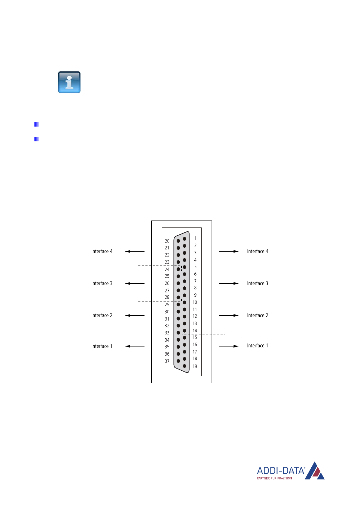
3) APCIe-7800
Fig. 3-8: APCIe-7800: 78-pin D-Sub female connector
Table 3-3: APCIe-7800: Pin assignment
Pin
Interface
RS232 RS422 RS422-PEP RS485 TTY
59 DCD TA(Tx+) TA(Tx+) TCollector (Tx+)
19 Rx TB(Tx-) TB(Tx-) TEmitter (Tx-)
20 Tx RA(Rx+) RA(Rx+) Tx/Rx+ DAnode (Rx+)
78 DTR RTermination IB (CTS-) RTermination
18 GND GND GND GND GND
58 DSR 100 ΩIA(CTS+) 120 Ω
39 RTS CB(RTS-) TSource
38 CTS CA(RTS+) RSource
77
UART 0
RI RB(Rx-) RB(Rx-) Tx/Rx- DCathode (Rx-)
37 DCD TA(Tx+) TA(Tx+) TCollector (Tx+)
75 Tx RA(Rx+) RA(Rx+) Tx/Rx+ DAnode (Rx+)
76
UART 1
Rx TB(Tx-) TB(Tx-) TEmitter (Tx-)
www.addi-data.com 17

Insertion and installation of the board APCIe-7xx0
Pin
Interface
RS232 RS422 RS422-PEP RS485 TTY
17 DTR RTermination I
B (CTS-) RTermination
74 GND GND GND GND GND
36 DSR
100 ΩIA(CTS+) 120 Ω
56 RTS CB(RTS-) TSource
55 CTS CA(RTS+) RSource
16
UART 1
RI RB(Rx-) RB(Rx-) Tx/Rx- DCathode (Rx-)
54 DCD TA(Tx+) TA(Tx+) TCollector (Tx+)
15 Rx TB(Tx-) TB(Tx-) TEmitter (Tx-)
14 Tx RA(Rx+) RA(Rx+) Tx/Rx+ DAnode (Rx+)
73 DTR RTermination IB (CTS-) RTermination
13 GND GND GND GND GND
53 DSR 100 ΩIA(CTS+) 120 Ω
34 RTS CB(RTS-) TSource
33 CTS CA(RTS+) RSource
72
UART 2
RI RB(Rx-) RB(Rx-) Tx/Rx- DCathode (Rx-)
32 DCD TA(Tx+) TA(Tx+) TCollector (Tx+)
71 Rx TB(Tx-) TB(Tx-) TEmitter (Tx-)
70 Tx RA(Rx+) RA(Rx+) Tx/Rx+ DAnode (Rx+)
12 DTR RTermination I
B (CTS-) RTermination
69 GND GND GND GND GND
31 DSR
100 ΩIA(CTS+) 120 Ω
51 RTS CB(RTS-) TSource
50 CTS CA(RTS+) RSource
11
UART 3
RI RB(Rx-) RB(Rx-) Tx/Rx- DCathode (Rx-)
49 DCD TA(Tx+) TA(Tx+) TCollector (Tx+)
10 Rx TB(Tx-) TB(Tx-) TEmitter (Tx-)
9 Tx RA(Rx+) RA(Rx+) Tx/Rx+ DAnode (Rx+)
68 DTR RTermination IB (CTS-) RTermination
8 GND GND GND GND GND
48 DSR
100 ΩIA(CTS+) 120 Ω
29
UART 4
RTS CB(RTS-) TSource
www.addi-data.com 18

Insertion and installation of the board APCIe-7xx0
Pin
Interface
RS232 RS422 RS422-PEP RS485 TTY
28 CTS CA(RTS+) RSource
67
UART 4
RI RB(Rx-) RB(Rx-) Tx/Rx- DCathode (Rx-)
27 DCD TA(Tx+) TA(Tx+) TCollector (Tx+)
66 Rx TB(Tx-) TB(Tx-) TEmitter (Tx-)
65 Tx RA(Rx+) RA(Rx+) Tx/Rx+ DAnode (Rx+)
7 DTR RTermination IB (CTS-) RTermination
64 GND GND GND GND GND
26 DSR 100 ΩIA(CTS+) 120 Ω
46 RTS CB(RTS-) TSource
45 CTS CA(RTS+) RSource
6
UART 5
RI RB(Rx-) RB(Rx-) Tx/Rx- DCathode (Rx-)
44 DCD TA(Tx+) TA(Tx+) TCollector (Tx+)
5 Rx TB(Tx-) TB(Tx-) TEmitter (Tx-)
4 Tx RA(Rx+) RA(Rx+) Tx/Rx+ DAnode (Rx+)
63 DTR RTermination I
B (CTS-) RTermination
3 GND GND GND GND GND
43 DSR
100 ΩIA(CTS+) 120 Ω
24 RTS CB(RTS-) TSource
23 CTS CA(RTS+) RSource
62
UART 6
RI RB(Rx-) RB(Rx-) Tx/Rx- DCathode (Rx-)
22 DCD TA(Tx+) TA(Tx+) TCollector (Tx+)
61 Rx TB(Tx-) TB(Tx-) TEmitter (Tx-)
60 Tx RA(Rx+) RA(Rx+) Tx/Rx+ DAnode (Rx+)
2 DTR RTermination IB (CTS-) RTermination
40 GND GND GND GND GND
21 DSR 100 ΩIA(CTS+) 120 Ω
42 RTS CB(RTS-) TSource
41 CTS CA(RTS+) RSource
1
UART 7
RI RB(Rx-) RB(Rx-) Tx/Rx- DCathode (Rx-)
A cable connection between the resistor (RS422/RS485) and RTermination activates the termination resistor.
www.addi-data.com 19

Insertion and installation of the board APCIe-7xx0
3.2.2 Connection cable ST075 (APCIe-7500)
This cable converts the 37-pin D-Sub male connector of the APCIe-7500 board to four 9-pin D-Sub
female connectors. The pin assignment is to be found in Chapter 3.2.1.
3.2.3 Connection cables ST074 (APCIe-7500) and ST7825 (APCIe-7800)
The ST074 cable converts the 37-pin D-Sub male connector of the APCIe-7500 board to four 25-pin
D-Sub female connectors.
The ST7825 cable converts the 78-pin D-Sub male connector of the APCIe-7800 board to eight 25-pin
D-Sub female connectors.
Fig. 3-9: APCIe-7500/4C, APCIe-7800 and breakout cables: 25-pin D-Sub male connector
Table 3-4: APCIe-7500, APCIe-7800 and breakout cables: Pin assignment
Pin
RS232
RS422 RS422-PEP
RS485 TTY
8 DCD TA(Tx+) TA(Tx+) TCollector (Tx+)
3 Rx TB(Tx-) TB(Tx-) TEmitter (Tx-)
2 Tx RA(Rx+) RA(Rx+) Tx/Rx+ DAnode (Rx+)
20 DTR RTermination
IB (CTS-) RTermination
7 GND GND GND GND GND
6 DSR 100 ΩIA(CTS+) 120 Ω
4 RTS CB(RTS-) TSource
5 CTS CA(RTS+) RSource
22 RI RB(Rx-) RB(Rx-) Tx/Rx- DCathode (Rx-)
A cable connection between the resistor (RS422/RS485) and RTermination activates the termination resistor.
www.addi-data.com 20
This manual suits for next models
3
Table of contents
Other Addi-Data Recording Equipment manuals

Popular Recording Equipment manuals by other brands

ARX
ARX Audibox USB-DI VC owner's manual

Tech Works
Tech Works CI-MSI-22 Quick reference guide

auto maskin
auto maskin RIO 425 installation manual

Universal Audio
Universal Audio Apollo Twin Hardware manual

microcell
microcell granular processor user manual

Tews Technologies
Tews Technologies TPMC460 user manual


