Addi-Data ADDICOM PA 7300 Parts list manual
Technical support:
+49 (0)7223 / 9493-0
Technical description
ADDICOM PA 7300
1-port serial interface
5
th edition 09/1999

Copyright
All rights reserved. This manual is intended for the manager and its personnel.
No part of this publication may be reproduced or transmitted by any means.
Offences can have penal consequences.
Guarantee and responsibility
Basically are effective our "general terms of delivery and payment". The manager receives them
at the latest with the invoice. Claims for guarantee and responsibility in case of injuries and
material damages are excluded, if they are due to one or some of the following causes:
- if the board has not been used for the intended purpose
- improper installation, operation and maintenance of the board
- if the board has been operated with defective safety devices or with not appropriate or
nonfunctioning safety equipment
- nonobservance of the instructions concerning: transport, storage, inserting the board, use,
limit values, maintenance, device drivers
- altering the board at the user's own initiative
- altering the source files at the user's own initiative
- not checking properly the parts which are subject to wear
- disasters caused by the intrusion of foreign bodies and by influence beyond the user's control.
Licence for ADDI-DATA software products
Read carefully this licence before using the software ADDISET and ADDIMON. The right for
using this software is given to the customer, if he/she agrees to the conditions of this licence.
- this software can only be used for configuring ADDI-DATA boards.
- copying the software is forbidden (except for archiving/ saving data and for replacing
defective data carriers)
- deassembling, decompiling, decoding and reverse engineering of the software are forbidden.
- this licence and the software can be transfered to a third party, so far as this party has purchased
a board, declares to agree to all the clauses of this licence contract and the preceding owner has not
kept copies of the software.
Trademarks
Borland C and Turbo Pascal are registered trademarks of Borland International, INC.
Burr-Brown is a registered trademark of Burr-Brown Corporation
Intel is a registered trademark of Intel Corporation
AT, IBM, ISA and XT are registered trademarks of International Business Machines Corporation
Microsoft, MS-DOS, Visual Basic and Windows are registered trademarks of Microsoft Corporation
The original version of this manual is in German. You can obtain it on request.

i
WARNING
In case of wrong uses and if the board is not used for
the purpose it is intended for:
people may be the board, PC and the environment
injured peripheral may be may be
destroyed polluted
«
««
««
««
««
««
«Protect yourself, the others and the environment«
««
««
««
««
««
«
•
••
•Do read the safety leaflet!
If this leaflet is not with the documentation, please contact us and ask for it.
•
••
•Observe the instructions of the manual!
Make sure that you do not forget or skip any step. We are not liable for
damages resulting from a wrong use of the board.
•
••
•Symbols used
WARNING!
It designates a possibly dangerous situation.
If the instructions are ignored the board, PC and/or peripheral
may be damaged.
IMPORTANT!
designates hints and other useful information.
•
••
•Any question?
Our technical support is at your disposal

iii
Declaration of Conformity
This declaration is valid for the following product:
ADDICOM PA 7300
1-port serial interface with/without galvanic separation
plug & play, modular structure through SI modules
It is made by
ADDI-DATA GmbH
Meß- und Steuerungstechnik
Dieselstraße 3
D-77833 Ottersweier
in sole responsibility and is valid on the understanding that the product is competently installed, used
and maintained, according to the respective security regulations as well as to the manufacturer's
instructions regarding its intended use.
This declaration states that the product complies with following EC Directives:
l
ll
lEWGRL 336/89 of 3.05.1989
l
ll
lEWGRL 31/92 of 28.04.1992
l
ll
lEWGRL 68/93 of 22.07.1993
This declaration is valid for all units manufactured according to the
manufacturing references listed in the form TD7300.020.
Following norms have been applied to test the product
regarding electromagnetic compatibility:
l
ll
lEN55011/03.91
l
ll
lEN55022/08.94
l
ll
lEN50082-2/03.95
We point out that
lthe conformity and herewith the permission of use expire if the user alters the product without
consulting with the manufacturer.
lnon-skilled users are to have the operational area of the product and the requirements
resulting from it checked prior to putting into operation.
lby using this product in appliances coming under the EC EMC Directive, the user is to make
sure they are conform to its regulations prior to putting into operation.
lby using this product in machines / installations coming under the EU Machine Directive,
the user is to make sure they are conform to its regulations prior to putting into operation.
A copy of the EMC tests is at your disposal on request.
15 October 1995 Legally valid signature of the manufacturer

Table of contents PA 7300
I
1INTENDED PURPOSE OF THE BOARD ....................................................1
1.1 Limits of use........................................................................................................ 3
2USER..................................................................................................4
2.1 Qualification ......................................................................................................4
2.2 Personal protection............................................................................................4
3HANDLING THE BOARD .......................................................................5
4TECHNICAL DATA................................................................................6
4.1 Electromagnetic compatibility (EMC).................................................................6
4.2 Physical set-up of the board .............................................................................. 6
4.3 Limit values.........................................................................................................7
5INSTALLATION.....................................................................................9
5.1 Inserting the board........................................................................................... 10
5.1.1 Opening the PC.........................................................................................................10
5.1.2 Selecting a free slot ...................................................................................................10
5.1.3 Plugging the board into the slot.................................................................................10
5.1.4 Closing the PC ...........................................................................................................11
5.2 Installing the software ...................................................................................... 12
5.2.1 Software installation under MS-DOS and Windows 3.11 .............................................12
5.2.2 Software installation under Windows NT / 95...............................................................12
5.3 Configuring the board with ADDISET................................................................. 13
5.3.1 Load ADDISET .............................................................................................................13
5.3.2 Configuration.............................................................................................................14
Configuring the base address and the interrupt line..................................................14
Configuring interface parameters .............................................................................14
5.3.3 Storing the configuration............................................................................................15
5.3.4 Define the "boot file" (initialization file)........................................................................15
Batch file AUTOEXEC.BAT ............................................................................................15
5.3.5 Modifying the configuration after having booted the PC ..........................................16
5.3.6 Quit ADDISET...............................................................................................................16
5.4 Testing the functions with ADDIMON.................................................................16
5.4.1 Hotline protocol, faster technical support..................................................................16
5.5 Board configuration with ADDIREG ...................................................................16
5.5.1 Program description ..................................................................................................16
5.5.2 Registrating a new board ..........................................................................................21
5.5.3 Changing the registration of a board ........................................................................21
5.5.4 Removing the ADDIREG program ..............................................................................22
5.6 Error analysis per Internet.................................................................................22
5.7 Operating systems with Plug & Play functions..................................................23

PA 7300 Table of contents
II
6CONNECTING THE PERIPHERAL......................................................... 24
6.1 Connector pin assignment ...............................................................................24
6.2 Connection examples ......................................................................................25
6.2.1 Cabling RS232...........................................................................................................25
6.2.2 Cabling RS422...........................................................................................................25
6.2.3 Cabling RS485...........................................................................................................26
6.2.4 Cabling 20 mA Current Loop.....................................................................................27
7REPLACING THE SI MODULES............................................................29
8DEVICE DRIVER ................................................................................31
INDEX..........................................................................................................A

Figures and tables PA 7300
III
Figures
Fig. 1-1: Combination of the basic board with SI modules.................................................... 1
Fig. 3-1: Wrong handling.......................................................................................................5
Fig. 3-2: Correct handling......................................................................................................5
Fig. 5-1: Types of slots .......................................................................................................... 10
Fig. 5-2: Opening the protective blister pack ...................................................................... 10
Fig. 5-3: Inserting the board................................................................................................. 11
Fig. 5-4: Fastening the board at the back cover ................................................................. 11
Fig. 5-5: Dialog box Configuration ....................................................................................... 13
Fig. 5-6: ADDIREG registration program ............................................................................... 17
Fig. 5-7: Configuring a new board....................................................................................... 19
Fig. 5-8: Communication board.......................................................................................... 20
Fig. 5-9: The ADDI-UNINSTALL program ................................................................................. 22
Fig. 6-1: 25-pin SUB-D male connector................................................................................ 24
Fig. 6-2: Cabling RS232 ...................................................................................................... 25
Fig. 6-3: Cabling RS422 ....................................................................................................... 25
Fig. 6-4: Cabling RS485 ....................................................................................................... 26
Fig. 6-5: Multipoint system.................................................................................................... 26
Fig. 6-6: Active transmission / active reception.................................................................... 27
Fig. 6-7: Active transmission / passive reception.................................................................. 27
Fig. 6-8: Passive transmission / active reception .................................................................. 27
Fig. 6-9: Passive transmission / passive reception ................................................................ 28
Fig. 6-10: Connection to a Siemens S5 SPS ......................................................................... 28
Fig. 7-1: Inserting a SI module.............................................................................................. 29
Fig. 7-2: Removing a SI module .......................................................................................... 29
Fig. 7-3: Component scheme of the basic board .............................................................. 30
Tables
Table 1-1: Intended purpose depending on the operating mode........................................ 2
Technical description Chapter 1 PA 7300
1
1 INTENDED PURPOSE OF THE BOARD
The board PA 7300 provides the personal computer (PC) with an asynchronous
serial interface for the communication with external devices.
The operating mode depends on the version of the basic board PA7300 and on
the SI modules installed.
The operating modes have different features regarding electromagnetic
compatibility.
The board is to be used in a free PC ISA slot. The PC is to comply with the EU
directive 89/336/EWG and the specifications for EMC protection.
Products complying with these specifications bear the mark.
The board supports serial communication through an asynchronous serial port.
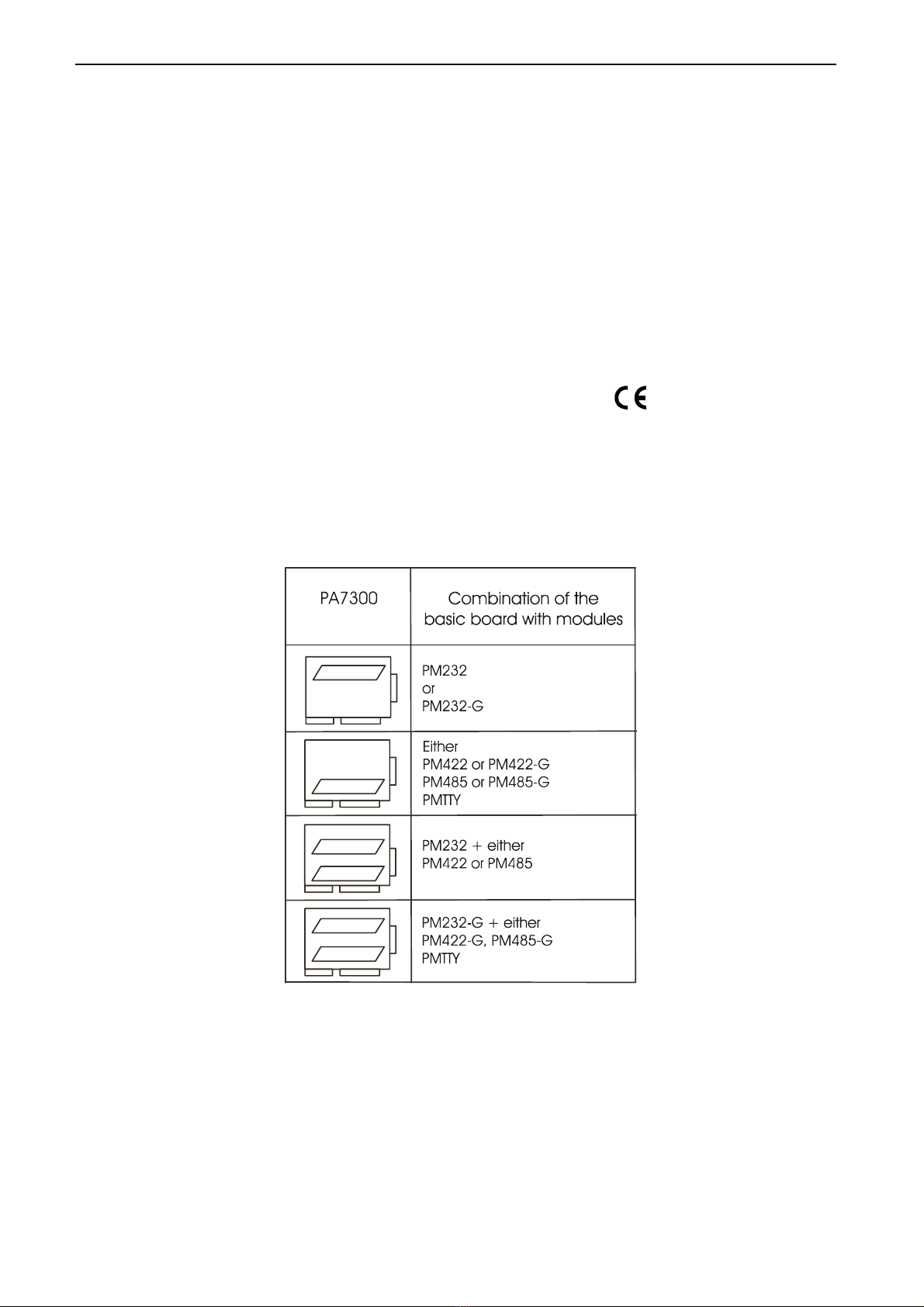
The following table shows the recommanded combinations of the basic board
PA7300 with the following SI modules:
Fig. 1-1: Combination of the basic board with SI modules

PA 7300 Technical description Chapter 1
2
The intended purpose of the board depends on the operating mode used.
Table 1-1: Intended purpose depending on the operating mode
Module1Operating
mode
Port
configuration
Distance
between
transmitter and
receiver 2
Environment
PM232
RS232
modem control signals
connected on the board
or externally to the
connector
30 m
industry
PM232-G
RS232
modem control signals
connected on the board
or externally to the
connector
30 m
noisy
industrial
environment
PMTTY 20 mA
Current loop
current flows
in rest state
1 km very noisy industrial
environment
PM422 RS422 1.2 km
noisy industrial
environment
PM422-G RS422 1.2 km
very noisy industrial
environment
PM 485
RS485
automatic transmitter
control
200 m industry
transmitter control
DTR, RTS or databit
1.2 km noisy industrial
environment
PM485-G RS485 automatic transmitter
control
200 m industry
transmitter control
DTR, RTS or databit
1.2 km very noisy industrial
environment
Connection to the peripheral
with a shielded cable, twisted in pairs.
Connect the peripheral cable so that the differential lines described in the
connector pin assignment with "+" and "-" are twisted in pairs.
Operating mode RS232: the signal lines are to be twisted in pairs with GND.
The housing of the peripheral connector
- is to be firmly screwed together with the shield of the cable
- is to assure a low-resistance connection (< 100 mΩ) between the shield and
the housing of the PC.
The shield of the cable is to be earthed on both ends.
The use of the board according to its intended purpose includes observing all
advices given in this manual and in the safety leaflet. Uses beyond these
specifications are not allowed. The manufacturer is not liable for any damages
which would result from the non-observance of this clause.
1PMxxx-G: ex. PM232-G means module for the mode RS 232 with option G (galvanic isolation)
PMTTY means module for the mode 20 mA current loop. It is isolated as a standard
2The max. lenghts are for standard interface cables

Technical description Chapter 1 PA 7300
3
1.1 Limits of use
The use of the board in a PC could change the PC features regarding noise
emission and immunity. Increased noise emission or decreased noise immunity
could result in the system not being conform anymore.
If the basic board PA7300 is used with galvanically separated SI modules,
then the creeping distance of 3.2 mm to the RS232 peripheral lines which are
not galvanically separated is not ensured anymore.
Our boards are not to be used for securing emergency stop functions.
The emergency stop functions are to be secured separately.
This securing must not be influenced by the board or the PC.
Make sure that the board remains in the protective blister pack until it is used.
Do not remove or alter the identification numbers of the board.
If you do, the guarantee expires.

PA 7300 Technical description Chapter 2
4
2 USER
2.1 Qualification
Only persons trained in electronics are entitled to perform the following tasks:
•Installation,
•putting into operation,
•use,
•maintenance.
2.2 Personal protection
Consider the country-specific regulations about
•the prevention of accidents
•electrical and mechanical installations
•radio interference suppression.
Technical description Chapter 3 PA 7300
5
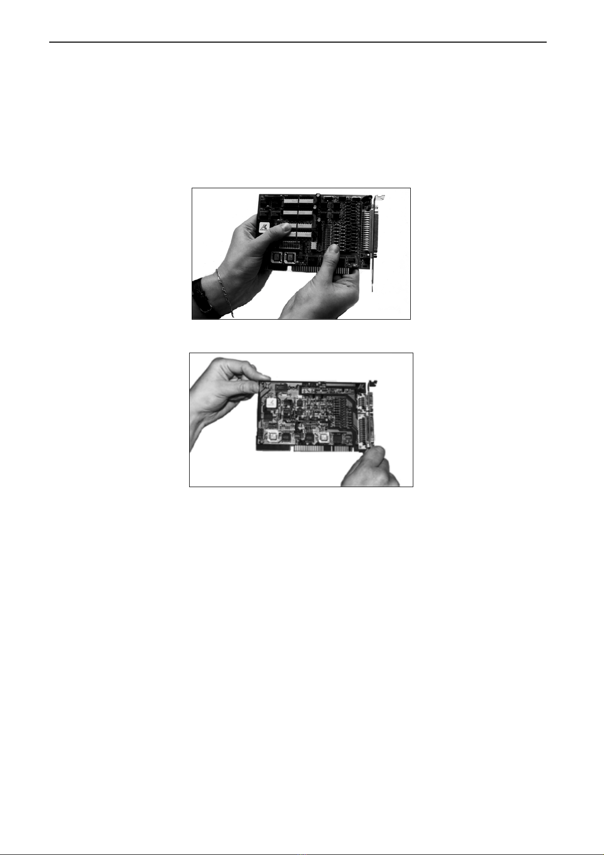
3 HANDLING THE BOARD
Fig. 3-1: Wrong handling
Fig. 3-2: Correct handling

PA 7300 Technical description Chapter 4
6
4 TECHNICAL DATA
4.1 Electromagnetic compatibility (EMC)
The board has been subjected to EMC tests in an accredited laboratory in
accordance with the norms EN50082-2, EN55011, EN55022.
The board complies with the limit values set by the norm EN50082-2 as follows:
True value Set value
ESD ................................................................... 4 kV 4 kV
Fields................................................................. 10 V/m 10 V/m
Burst.................................................................. 4 kV 2 kV
Conducted radio interferences .......................... 10 V 10 V
WARNING!
The EMC tests have been carried out in a specific appliance
configuration. We guarantee these limit values only in this
configuration.
Consider the following aspects:
- Use properly shielded lines
- your test program must be able to detect operation errors.
- your system must be set up so that you can find out what caused errors.
4.2 Physical set-up of the board
The board is assembled on a 2-layer printed circuit card.
Approximate card dimensions
(with components)
with SI modules Lenght: 125 mm
Max. height: 18 mm
Breadth: 76 mm
Weight: Max. 108 g
Installation in: AT slot
Connection to the peripheral: 25-pin SUB-D male connector

Technical description Chapter 4 PA 7300
7
4.3 Limit values
Operating temperature: .................................... 0 to 60°C
Storage temperature: ........................................ -25 to 70°C
Relative humidity: ........................................... 30% to 99% non condensing
Minimum PC requirements:
- operating system: ........................................... MS DOS 3.3 or >
Windows 3.1
- bus speed: ...................................................... 8 MHz
Energy requirements:
- operating voltage of the PC: .......................... 5V ±5%
- current consumption in mA(without load): typ. See table ±10%
PA7300
+ 5 V from PC 63 mA
Add to this data the current consumption of the used
modules according to following table.
PMxxx1PMxxx-G
RS232 21 mA 48 mA
RS422 5 mA 42 mA
RS485 5 mA 53,5 mA
20mA 51 mA -
1Module PMTTY (20 mA) is isolated as a standard.

PA 7300 Technical description Chapter 4
8
PM232 CCITT recommendation..................... V.24
US norm EIA ...................................... RS232
max. transfer rate ................................ 112 kBd
PM232-G CCITT recommendation..................... V.24
US norm EIA ...................................... RS232
max. transfer rate ................................ 19200 Bd
Creeping distance ............................... 3.2 mm
Test voltage......................................... 1000 VAC
PM422, CCITT recommendation..................... V.11
PM485 US norm EIA...................................... RS422, RS485
Transil diodes:
Absorption power 1ms........................ 400 W
Breakdown voltage ............................. +/- 6,5 V
max. transfer rate ................................ 112 kBd
max. transfer rate on request ......... 1 MBd
Short circuit protection ....................... PTC
PM422-G, CCITT recommendation..................... V.11
PM485-G US norm EIA ...................................... RS422, RS485
Transil diodes
Absorption power 1 ms....................... 400 W
Breakdown voltage ............................. ±6,5 V
max. transfer rate ................................ 112 kBd
max. transfer rate on request ......... 1 MBd
Short circuit protection ....................... PTC
Creeping distance ............................... 3.2 mm
Test voltage......................................... 1000 VAC
The standard basic board has a transfer rate of 112 kBd. If you wish to
transmit at 1MBaud, then the basic board has to be configured again by our
services.
1MBd configuration: Please consider that the divider factors for programming
the transfer rate do not comply with the PC standard anymore.
The 1M Bd transfer rate can only be programmed with the device drivers
delivered with the board.
RS 485: transfer at 1 MBaud only works when the transmitter is controlled
through DTR, RTS or data bit.
PMTTY 20mA Current Loop
max. transfer rate ............................... 19200 Bd
Transil diodes:
Absorption power 1ms........................ 300 W
Breakdown voltage ............................. +/- 26 V
Creeping distance ............................... 3.2 mm
Test voltage......................................... 1000 VAC

Technical description Chapter 5 PA 7300
9
5 INSTALLATION
IMPORTANT!
If you want to install SIultaneously several ADDI-DATA Plug & Play
boards, consider the following procedure.
•Install and configure the boards one after the other.
You will thus avoid configuration errors.
1. Switch off the PC
2. Install the first board
3. Start the PC
4. Install the software (once is enough)
5. Configure the board
6. Switch off the PC
7. Install the second board
8. Start the PC
9. Configure the board
etc
You will find additional information to these different steps in the sections 5.1
to 5.4.
IMPORTANT!
You have installed already one or more ADDI-DATA Plug & Play
boards in your PC, and you wish to install an additional board?
Proceed as if you wished to install one single board.
PA 7300 Technical description Chapter 5
10
5.1 Inserting the board
IMPORTANT!
Do observe the safety instructions.
5.1.1 Opening the PC
•Switch off your PC and all the units connected to the PC.
•Pull the PC's mains plug from the socket.
•Open your PC as described in the manual of the PC manufacturer.
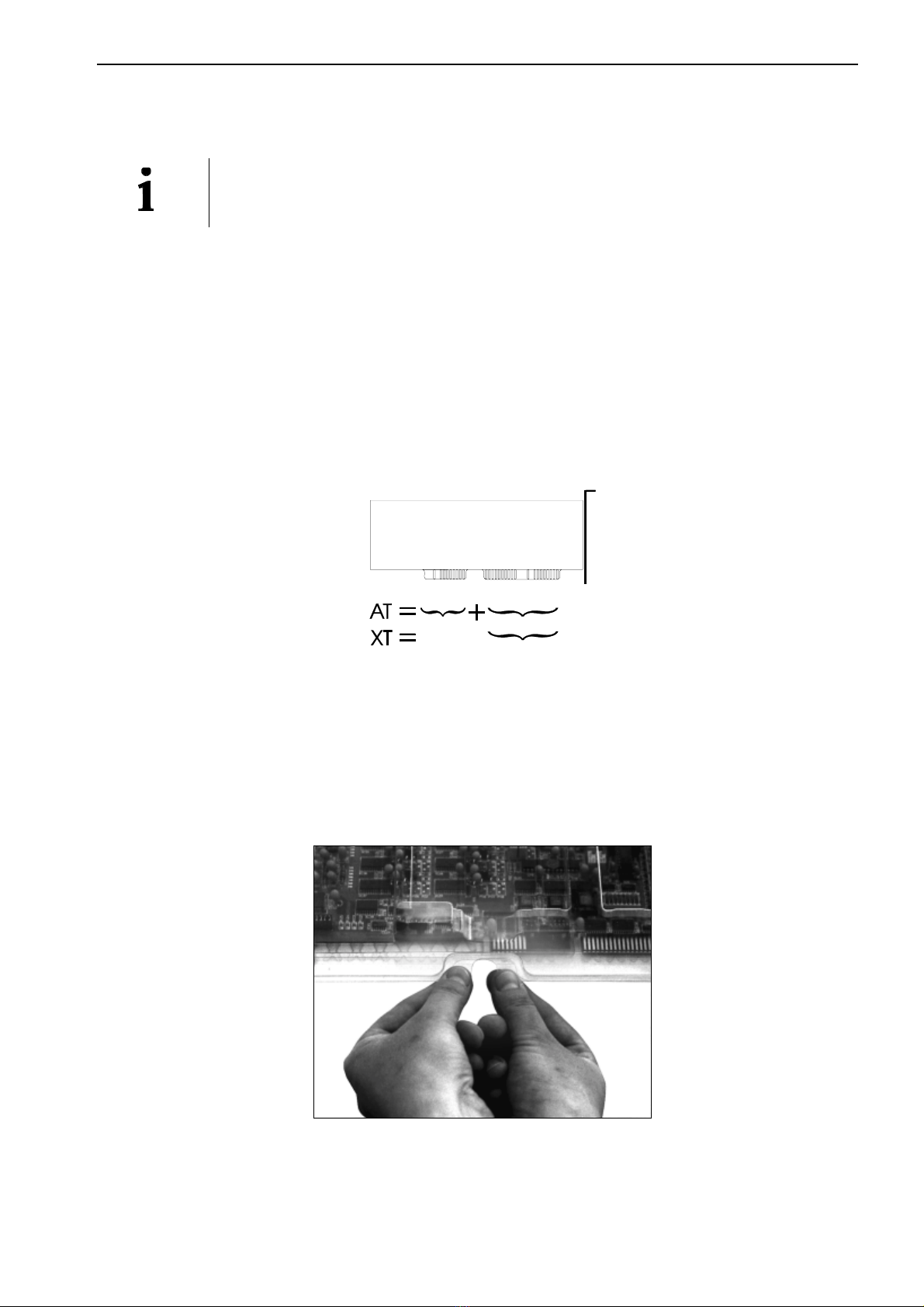
5.1.2 Selecting a free slot
Two types of ISA slots are available: XT and AT.
Fig. 5-1: Types of slots
If necessary, the board can also be used in EISA slots under certain conditions.
See in the PC manual which types of slots are free.
1. Decide in which type of slot to insert the board.
2. Remove the back cover of the selected slot according to the instructions of the
PC manufacturer. Keep the back cover. You will need it if you remove the board.
3. Discharge yourself from electrostatic charges.
4. Take the board out of its protective blister pack.
Fig. 5-2: Opening the protective blister pack
5.1.3 Plugging the board into the slot
•
••
•Discharge yourself from electrostatic charges.
•
••
•Insert the board vertically into the chosen slot.

Technical description Chapter 5 PA 7300
11
Fig. 5-3: Inserting the board
•Fasten the board to the rear of the PC housing with the screw
which was fixed on the back cover.
Fig. 5-4: Fastening the board at the back cover
•
••
•Tighten all the loosen screws.
5.1.4 Closing the PC
•Close your PC as described in the manual of the PC manufacturer.

PA 7300 Technical description Chapter 5
12
5.2 Installing the software
The board is supplied with a CD-ROM.
The CD contains:
- ADDIREG for Windows NT 4.0 and Windows 95,
You can also download the ADDIREG program from Internet.
- Standard software for the ADDI-DATA boards:
- 16-bit for MS-DOS and Windows 3.11
- 32-bit for Windows NT/95.
5.2.1 Software installation under MS-DOS and Windows 3.11
- Copy the contents of PA7300\16bit on a diskette.
If several diskettes are to be used, the directory content is stored in several sub-
directories (Disk1, Disk2, Disk3...).
- Insert the (first) diskette into a driver and change to this drive.
- Enter <INSTALL>.
The installation program gives you further instructions.
5.2.2 Software installation under Windows NT / 95
- Select the directory PA7300\32bit\Disk1.
- Start the setup program "setup.exe" (double click)
- Select one of the 3 parameters
1- typical
2- compact
3- custom
Proceed as indicated on the screen and read attentively the "Software License"
and "Readme".
In "custom", you can select your operating system.
The installation program gives you further instructions.

Technical description Chapter 5 PA 7300
13
5.3 Configuring the board with ADDISET
5.3.1 Load ADDISET
In the directory ADDISET, type <ADDISET>.
The parametering program for the board PA 7300 is loaded.
ADDISET lists automatically all the plug & play ADDI-DATA boards which
are plugged in your PC. They appear in the board list in the order in which they
have been detected by the chain of characters identifying the board. Port 1 is
detected before Port 2.
Make sure that ADDISET has detected all the boards.
You move the cursor on the port you wish to configure. It is highlighted. Klick
on the button Configuration and the following dialog box appears:
Fig. 5-5: Dialog box Configuration
IMPORTANT!
When configuring a Plug & Play board make sure that no other
Plug & Play board is active.
Network boards: a plug & play network board should not be coupled to a
network, when an ADDI-DATA plug & play board is being configurated.
This may cause the PC being unstable.
Table of contents
Other Addi-Data Recording Equipment manuals


