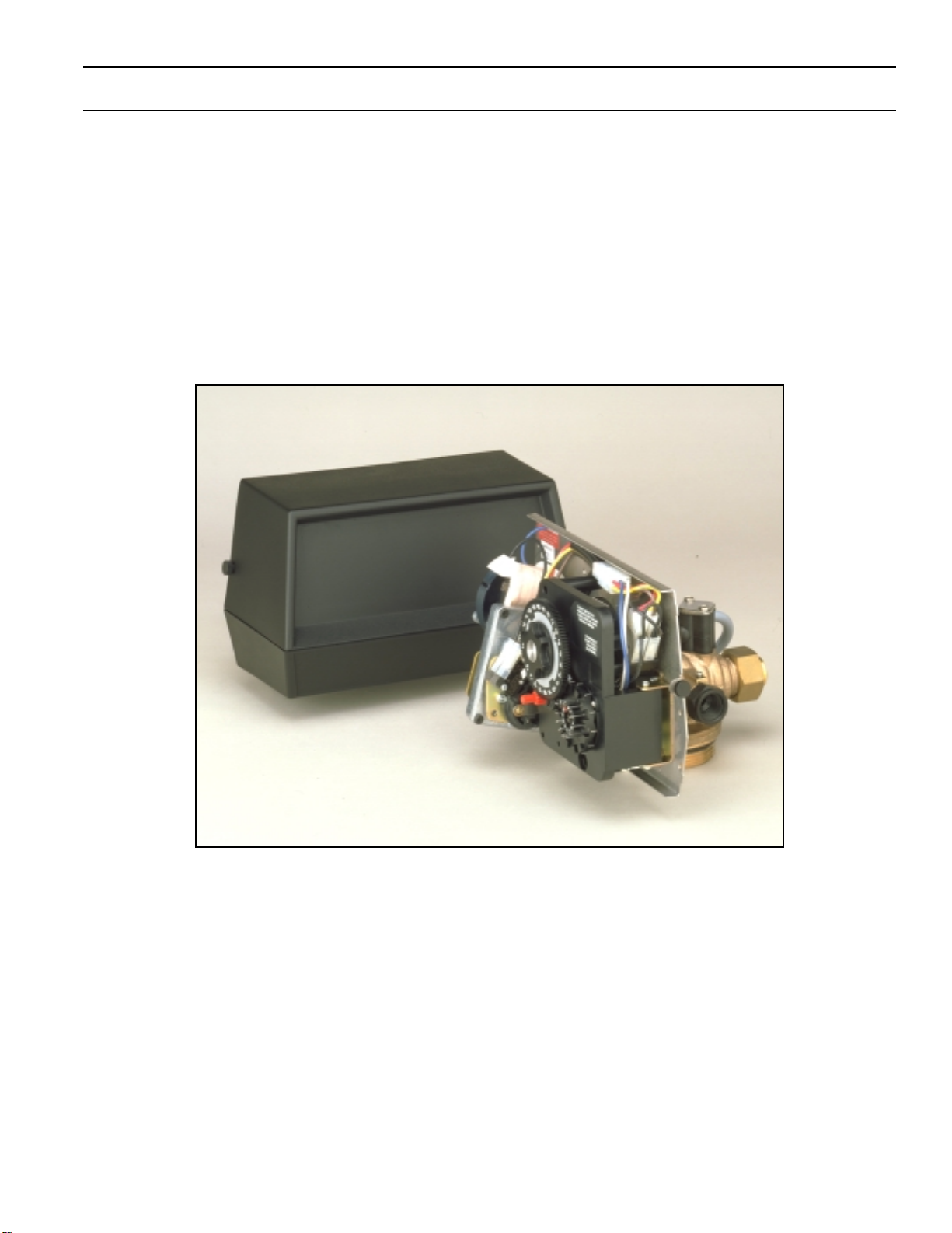
Addie Water Systems 2500 User manual
IMPORTANT: Fill in pertinent information on page 2 for future reference.
MODEL 2500 & 1500
Service Manual

MODEL 2500 & 1500
Job Specification Sheet
Printed in U.S.A.
* JOB NO. _________________________________________________________
* MODEL NO. _______________________________________________________
* WATER TEST _____________________________________________________
* CAPACITY PER UNIT ____________ MAX. __________ PER REGENERATION
* MINERAL TANK SIZE DIA. ________________ HEIGHT___________________
* BRINE TANK SIZE &
SALT SETTING PER REGENERATION: _________________________________
Page 2
* CONTROL VALVE SPECIFICATIONS
1) Type of Timer
A) 7 day _________
B) 12 day _________
2) Regeneration Cycle
A) Separate Time Fill ________
B) Rapid Rinse ________
3) Regeneration Program Settings (see pages 6 & 7)
A) Backwash ___________________________ min.
B) Brine & Slow Rinse ____________________ min.
C) Rapid Rinse _________________________ min.
D) Brine Tank Refill_______________________ min.
4) Drain Line Flow Controller __________________ gpm
5) Brine Refill Rate_________________________________
6) Injector Size ____________________________________
MODEL 2500 & 1500

Printed in U.S.A.
Page 3
MODEL 2500 & 1500
Installation Instructions
The water softener should be installed with the inlet, outlet and drain connections made in accordance with
manufacturer’s recommendations and to meet applicable plumbing codes.
1. Remove control box cover.
2. Make “Time of Day” setting and set “Skipper Wheel.” (See time control instructions.)
3. Observe regeneration cycle settings. (These are factory preset and need no adjustment.)
4. Add three inches of water to brine tank.
5. NOTE: To set the control to the various positions noted below — turn the manual regeneration knob slowly in a
clockwise direction until the drive motor runs and positions the valve drive shaft (located in the lower center of the
control box).
Control Valve Positions (see pages 8 and 9)
Service —Drive shaft out
Backwash —Drive shaft in
Brine and Rinse —Drive shaft 1/2 way out
Brine Tank Fill —Drive shaft out but brine cam holds brine valve stem in.
6. Run water through softener with control in service position for at least three (3) minutes to settle bed.
7. Position valve to backwash and check to make sure that drain line flow remains steady for ten (10) minutes.
8. Position valve to brine tank fill and check to see if tank is filling.
9. Position valve to brine position and check suction.
10. Position valve to start of brine tank fill cycle. Brine valve drive cam will hold valve in at this position to fill the brine
tank for the first regeneration.
11. Replace control box cover.
12. Check power cord connection. (Note: Make sure control is plugged into a non-interrupted electrical circuit).
13. Put salt in brine tank. (Do not use granulated salt.)
Printed in U.S.A.
Page 4
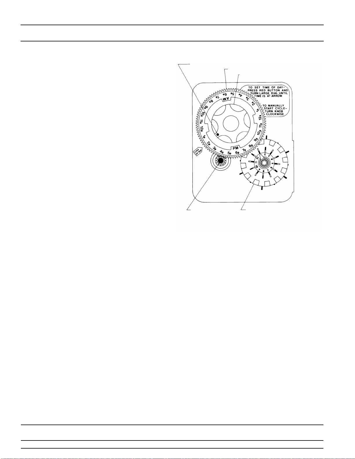
MODEL 3200 TIMER
Timer Setting Procedure
How To Set Days On Which Water Conditioner Is To
Regenerate:
Rotate the skipper wheel until the number “1” is at the red
pointer. Set the days that regeneration is to occur by
sliding tabs on the skipper wheel outward to expose trip
fingers. Each tab is one day. Finger at red pointer is
tonight. Moving clockwise from the red pointer, extend or
retract fingers to obtain the desired regeneration
schedule.
How To Set The Time Of Day:
Press and hold the red button in to disengage the drive
gear.
Turn the large gear until the actual time of day is at the
time of day pointer.
Release the red button to again engage the drive gear.
How To Manually Regenerate Your Water Conditioner
At Any Time:
Turn the manual regeneration knob clockwise.
This slight movement of the manual regeneration knob
engages the program wheel and starts the regeneration
program.
The black center knob will make one revolution in the
following approximately three hours and stop in the
position shown in the drawing.
Even though it takes three hours for this center knob to
complete one revolution, the regeneration cycle of your
unit might be set only one half of this time.
In any event, conditioned water may be drawn after rinse
water stops flowing from the water conditioner drain line.
SERVICE
POSITION
INDICATOR
24 HR. GEAR
MANUAL REGENERATION KNOB
RED TIME
SET BUTTON SKIPPER WHEEL
(SHOWS EVERY OTHER
DAY REGENERATION)
IMPORTANT!
SALT LEVEL MUST ALWAYS BE ABOVE WATER LEVEL IN BRINE TANK.
Printed in U.S.A.
Page 5
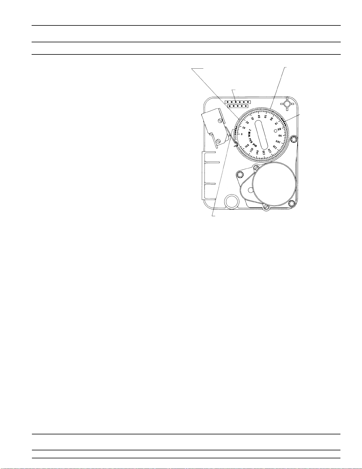
MODEL 3200 TIMER
Regeneration Cycle Program Setting Procedure
(Rapid Rinse) White Drive Cam and Brine Valve Cam
How to Set The Regeneration Cycle Program:
The regeneration cycle program on your water conditioner
has been factory preset, however, portions of the cycle or
program may be lengthened or shortened in time to suit
local conditions.
To expose cycle program wheel, grasp timer in upper left-
hand corner and pull, releasing snap retainer and
swinging timer to the right.
To change the regeneration cycle program, the program
wheel must be removed. Grasp program wheel and
squeeze protruding lugs towards center, lift program
wheel off timer. (Switch arms may require movement to
facilitate removal.)
How To Change The Length Of The Backwash Time:
The program wheel as shown in the drawing is in the
service position. As you look at the numbered side of the
program wheel, the group of pins starting at zero deter-
mines the length of time your unit will backwash.
FOR EXAMPLE: If there are six pins in this section, the
time of backwash will be 12 min. (2 min. per pin). To
change the length of backwash time, add or remove pins
as required. The number of pins times two equals the
backwash time in minutes. (Note: Do not add pins
before “0” minutes designation.)
How To Change The Length Of Brine And Rinse Time:
The group of holes between the last pin in the backwash
section and the second group of pins determines the
length of time that your unit will brine and rinse. (2 min.
per hole.)
To change the length of brine and rinse time, move the
rapid rinse group of pins to give more or fewer holes in the
brine and rinse section. Number of holes times two
equals brine and rinse time in minutes.
How To Change The Length Of Rapid Rinse And Brine
Tank Fill Time:
The second group of pins on the program wheel
determines the length of time that your water conditioner
will rapid rinse and brine tank fill. (2 min. per pin.)
To change the length of rapid rinse and brine tank fill time,
add or remove pins at the higher numbered end of this
section as required. The number of pins times two equals
the rapid rinse and brine tank fill time in minutes.
The regeneration cycle is complete when the outer micro-
switch drops off the last pin in the rapid rinse and brine
tank fill group of pins. The program wheel, however, will
continue to rotate until the inner micro-switch drops into
the notch on the program wheel.
Return timer to closed position engaging snap retainer in
back plate. Make certain all electrical wires locate above
snap retainer post.
BRINE & RINSE
SECTION
(2 MIN. PER HOLE)
PIN STORAGE
PROGRAM
WHEEL FOR
CONTROL OF
REGENERATION
CYCLE
RAPID
RINSE &
BRINE TANK
REFILL
SECTION
(2 MIN.
PER PIN)
BACKWASH
SECTION
(2 MIN. PER PIN)
IMPORTANT!
SALT LEVEL MUST ALWAYS BE ABOVE WATER LEVEL IN BRINE TANK.
Printed in U.S.A.
Page 6
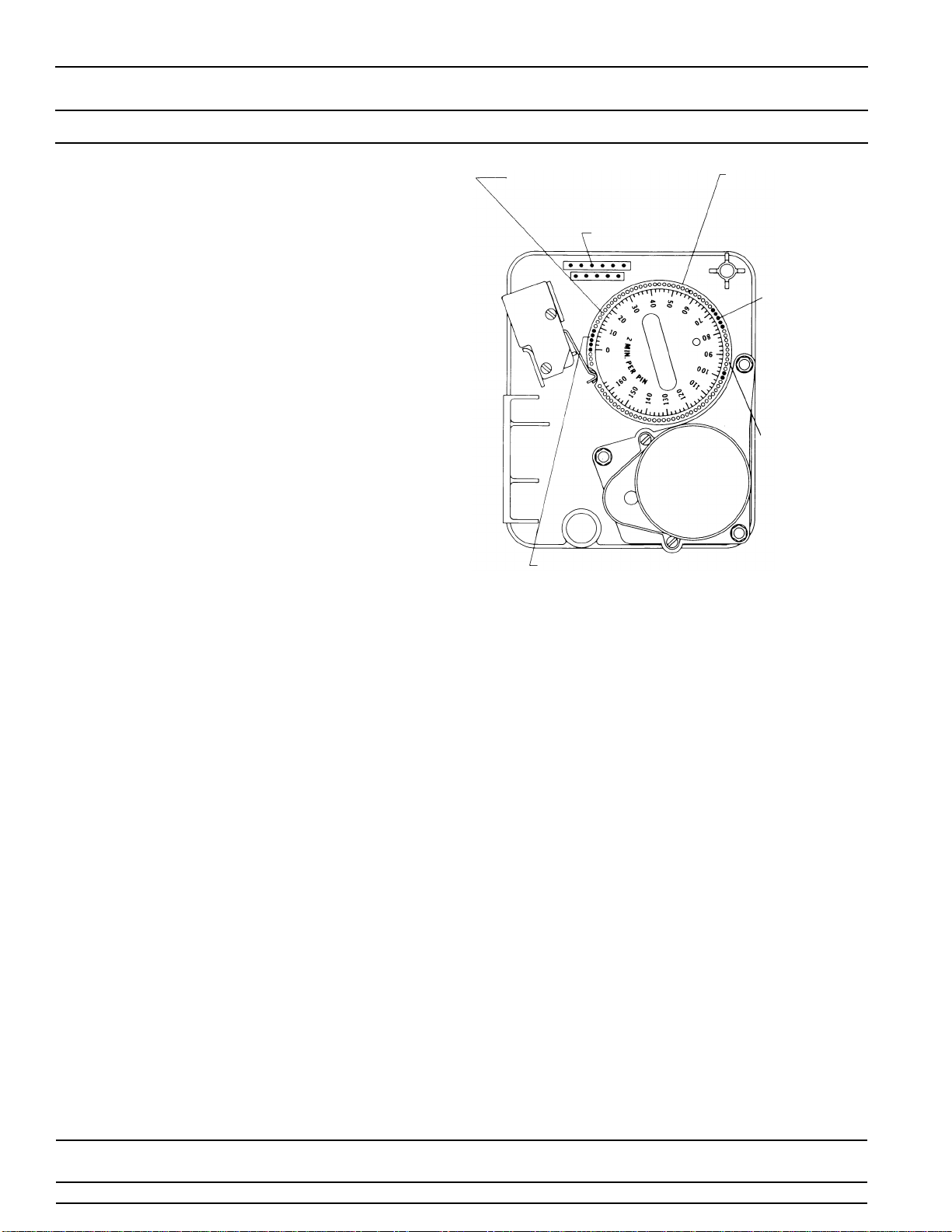
MODEL 3200 TIMER
Regeneration Cycle Program Setting Procedure
(Brine Tank Refill Separate From Rapid Rinse — STF) Black Drive Cam and Brine Valve Cam
How to Set The Regeneration Cycle Program:
The regeneration cycle program on your water conditioner
has been factory preset, however, portions of the cycle or
program may be lengthened or shortened in time to suit
local conditions.
To expose cycle program wheel, grasp timer in upper left-
hand corner and pull, releasing snap retainer and
swinging timer to the right.
To change the regeneration cycle program, the program
wheel must be removed. Grasp program wheel and
squeeze protruding lugs towards center, lift program
wheel off timer. (Switch arms may require movement to
facilitate removal.)
How To Change The Length Of The Backwash Time:
The program wheel as shown in the drawing is in the
service position. As you look at the numbered side of the
program wheel, the group of pins starting at zero deter-
mines the length of time your unit will backwash.
FOR EXAMPLE: If there are six pins in this section, the
time of backwash will be 12 min. (2 min. per pin). To
change the length of backwash time, add or remove pins
as required. The number of pins times two equals the
backwash time in minutes. (Note: Do not add pins
before “0” minutes designation.)
How To Change The Length Of Brine And Rinse Time:
The group of holes between the last pin in the backwash
section and the second group of pins determines the
length of time that your unit will brine and rinse. (2 min.
per hole.)
To change the length of brine and rinse time, move the
rapid rinse group of pins to give more or fewer holes in the
brine and rinse section. Number of holes times two
equals brine and rinse time in minutes.
How To Change The Length Of Rapid Rinse:
The second group of pins on the program wheel
determines the length of time that your water conditioner
will rapid rinse. (2 min. per pin.)
To change the length of rapid rinse time, add or remove
pins at the higher numbered end of this section as
required. The number of pins times two equals the rapid
rinse time in minutes.
How To Change The Length Of Brine Tank Refill Time:
The second group of holes on the program wheel deter-
mines the length of time that your water conditioner will
refill the brine tank. (2 min. per hole.)
To change the length of refill time, move the two pins at
the end of the second group of holes as required.
The regeneration cycle is complete when the outer micro-
switch is tripped by the two pin set at end of the brine tank
refill section. The program wheel, however, will continue
to rotate until the inner micro-switch drops into the notch
on the program wheel.
Return timer to closed position engaging snap retainer in
back plate. Make certain all electrical wires locate above
snap retainer post.
BRINE & RINSE
SECTION
(2 MIN. PER HOLE)
PIN STORAGE
PROGRAM
WHEEL FOR
CONTROL OF
REGENERATION
CYCLE
RAPID
RINSE
SECTION
(2 MIN.
PER PIN)
BACKWASH
SECTION
(2 MIN. PER PIN)
BRINE TANK
REFILL
SECTION
(2 MIN.
PER HOLE)
IMPORTANT!
SALT LEVEL MUST ALWAYS BE ABOVE WATER LEVEL IN BRINE TANK.
Printed in U.S.A.
Page 7
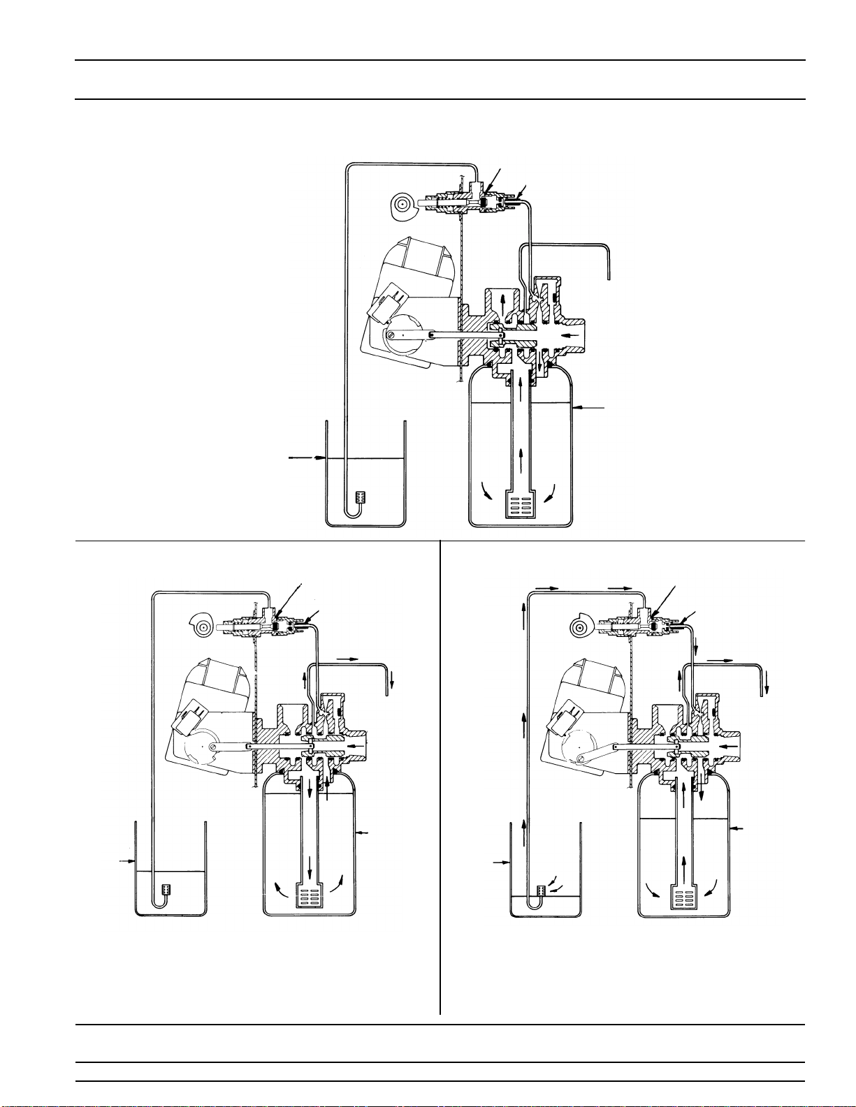
MODEL 2500 & 1500
Water Conditioner Flow Diagrams
1. SERVICE POSITION
Hard water enters unit at valve
inlet and flows down thru the
mineral in the mineral tank.
Conditioned water enters center
tube thru the bottom distributor
— then flows up thru the center
tube — around the piston and
out the top outlet of the valve.
Hard water enters unit at valve inlet — flows thru piston —
down center tube — thru bottom distributor and up thru the
mineral — around the piston and out the drain line.
Hard water enters unit at valve inlet — flows up into injector
housing and down thru nozzle and orifice to draw brine from
the brine tank — brine flows down thru mineral and enters the
center tube thru bottom distributor — flows up thru center tube
— around the piston and out thru the drain line.
2. BACKWASH POSITION 3. BRINE POSITION
BRINE VALVE
FLOW CONTROL
DRAIN
INLET
MINERAL
BRINE TANK
OUTLET
BRINE VALVE
FLOW
DRAIN
INLET
MINERAL
BRINE
OUTLET
TANK
CONTROL
TANK
TANK
BRINE VALVE
FLOW
DRAIN
INLET
MINERAL
BRINE
OUTLET
CONTROL
TANK
TANK

Printed in U.S.A.
Page 8
MODEL 2500 & 1500
Water Conditioner Flow Diagrams (Cont’d.)
Hard water enters unit at valve inlet — flows up into injector
housing and down thru nozzle and orifice — around the
piston — down thru mineral — enters center tube thru
bottom distributor flows up thru center tube — around piston
and out thru drain line.
Hard water enters unit at valve inlet — flows up thru injector
housing and thru brine valve to fill brine tank — hard water
also flows directly from inlet down thru mineral into center
tube bottom distributor and up thru center tube — around
piston and out thru the drain line.
Hard water enters unit at valve inlet — flows up thru injector
housing and thru brine valve to fill brine tank hard water also
flows directly from inlet down thru mineral into center tube
bottom distributor and up thru center tube — around piston
and out thru the drain line. Hard water enters unit at valve inlet — flows up thru the
injector housing — thru the brine valve to fill the brine tank.
4. SLOW RINSE POSITION 5. RAPID RINSE & BRINE TANK FILL
6. RAPID RINSE 7. BRINE TANK FILL POSITION
FOR SEPARATE TIME FILL ONLY
BRINE VALVE
FLOW
DRAIN
INLET
MINERAL
BRINE
OUTLET
CONTROL
TANK
TANK
BRINE VALVE
FLOW
DRAIN
INLET
MINERAL
BRINE
OUTLET
CONTROL
TANK
TANK
BRINE VALVE
FLOW
DRAIN INLET
MINERAL
OUTLET
CONTROL
TANK
BRINE
TANK
BRINE VALVE
FLOW
INLET
MINERAL
OUTLET
CONTROL
TANK
BRINE
TANK

Printed in U.S.A.
Page 9
Notes
Printed in U.S.A.
Page 10
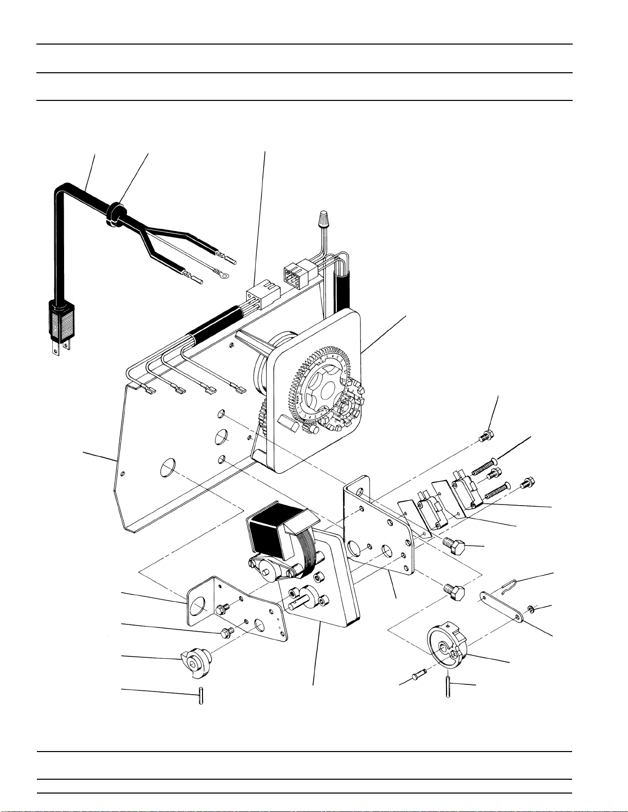
MODEL 2500 & 1500
Control Valve Drive Assembly
(See opposite page for parts list)
1
2
345
7
10
11
12
13
14
15
16
17
18 19
20
21
22
23
7
18

Printed in U.S.A.
Page 11
MODEL 2500 & 1500
Control Valve Drive Assembly
Parts List
Item No. Quantity Part No. Description
1. . . . . . . . . . . 1 . . . . . . . . . . . 14884 . . . . . . . . . . . . . . . Back Plate - Stainless Steel
1 . . . . . . . . . . . 11209 . . . . . . . . . . . . . . . Back Plate - Slant Front (not shown)
2. . . . . . . . . . . 1 . . . . . . . . . . . . . . . . . . . . . . . . . . . . . . . . 3200, 3000 Timer 7 or 12 Day
3. . . . . . . . . . . 1 . . . . . . . . . . . 11838 . . . . . . . . . . . . . . . Power Cord
4. . . . . . . . . . . 1 . . . . . . . . . . . 13547 . . . . . . . . . . . . . . . Strain Relief
5. . . . . . . . . . . 1 . . . . . . . . . . . 11667 . . . . . . . . . . . . . . . Wire Harness
6. . . . . . . . . . . . . . . . . . . . . . . . . . . . . . . . . . . . . . . . . . . . Not Assigned
7. . . . . . . . . . . 5 . . . . . . . . . . . 10872 . . . . . . . . . . . . . . . Screw - Motor Mounting
8. . . . . . . . . . . . . . . . . . . . . . . . . . . . . . . . . . . . . . . . . . . . . Not Assigned
9. . . . . . . . . . . . . . . . . . . . . . . . . . . . . . . . . . . . . . . . . . . . . Not Assigned
10 . . . . . . . . . . 1 . . . . . . . . . . . 10774 . . . . . . . . . . . . . . . Bracket - Motor Mounting
11 . . . . . . . . . . 2 . . . . . . . . . . . 10231 . . . . . . . . . . . . . . . Screw - Drive Mounting
12 . . . . . . . . . . 2 . . . . . . . . . . . 10302 . . . . . . . . . . . . . . . Insulator
13 . . . . . . . . . . 2 . . . . . . . . . . . 10218 . . . . . . . . . . . . . . . Switch
14 . . . . . . . . . . 1 . . . . . . . . . . . 10909 . . . . . . . . . . . . . . . Connecting Link Pin
15 . . . . . . . . . . 1 . . . . . . . . . . . 10250 . . . . . . . . . . . . . . . Retaining Ring
16 . . . . . . . . . . 1 . . . . . . . . . . . 10621 . . . . . . . . . . . . . . . Connecting Link
17 . . . . . . . . . . 1 . . . . . . . . . . . 12576 . . . . . . . . . . . . . . . Drive Cam - STE (Black)
1 . . . . . . . . . . . 12102 . . . . . . . . . . . . . . . Drive Cam - RR (White)
18 . . . . . . . . . . 2 . . . . . . . . . . . 10338 . . . . . . . . . . . . . . . Roll Pin
19 . . . . . . . . . . 1 . . . . . . . . . . . 13366 . . . . . . . . . . . . . . . Drive Bearing
20 . . . . . . . . . . 2 . . . . . . . . . . . 14923 . . . . . . . . . . . . . . . Screw - Switch Mounting
21 . . . . . . . . . . 1 . . . . . . . . . . . 10769 . . . . . . . . . . . . . . . Motor
22 . . . . . . . . . . 1 . . . . . . . . . . . 11826 . . . . . . . . . . . . . . . Bracket - Brine Valve Side
23 . . . . . . . . . . 1 . . . . . . . . . . . 12777 . . . . . . . . . . . . . . . Brine Valve Cam - STE (Black)
1 . . . . . . . . . . . 10815 . . . . . . . . . . . . . . . Brine Valve Cam - RR (White)
24 . . . . . . . . . . 2 . . . . . . . . . . . 10300 . . . . . . . . . . . . . . . Screw - Timer Mounting (not shown)
25 . . . . . . . . . . 1 . . . . . . . . . . . 13741 . . . . . . . . . . . . . . . Hole Plug (not shown)
26 . . . . . . . . . . 1 . . . . . . . . . . . 17904 . . . . . . . . . . . . . . . Hole Plug (not shown)
COVER MOUNTING HARDWARE
Stainless Steel
Back Plate. . . . 2 . . . . . . . . . . . 19367 . . . . . . . . . . . . . . . Screw
Slant Front
Back Plate. . . . 4 . . . . . . . . . . . 10300 . . . . . . . . . . . . . . . Screw

Printed in U.S.A.
Page 12
MODEL 2500
Control Valve Assembly
(See opposite page for parts list)
34
5
6
7
8
9
10
11
12
13 14
15
16
17
18
19
20 21 22 23
24
25
26
27
28
29
30
31
32 12
4
3
24

Printed in U.S.A.
Page 13
MODEL 2500
Control Valve Assembly
Parts List
Item No. Quantity Part No. Description
1. . . . . . . . . . . . 1 . . . . . . . . . . . . .11212. . . . . . . . . . . . . . . . . . Valve Body
2. . . . . . . . . . . . 1 . . . . . . . . . . . . .10757. . . . . . . . . . . . . . . . . . End Spacer
1 . . . . . . . . . . . . .10757B. . . . . . . . . . . . . . . . . End Spacer, Hot Water
3. . . . . . . . . . . . 6 . . . . . . . . . . . . .10545. . . . . . . . . . . . . . . . . . Seal Ring
4. . . . . . . . . . . . 5 . . . . . . . . . . . . .11451. . . . . . . . . . . . . . . . . . Spacer
5 . . . . . . . . . . . . .16589. . . . . . . . . . . . . . . . . . Spacer, Hot Water
5. . . . . . . . . . . . 1 . . . . . . . . . . . . .15168. . . . . . . . . . . . . . . . . . Piston
6. . . . . . . . . . . . 1 . . . . . . . . . . . . .14309. . . . . . . . . . . . . . . . . . Piston Rod Retainer
1 . . . . . . . . . . . . .16590. . . . . . . . . . . . . . . . . . Piston Rod Retainer, Hot Water
7. . . . . . . . . . . . 1 . . . . . . . . . . . . .14452. . . . . . . . . . . . . . . . . . Piston Rod
8. . . . . . . . . . . . 1 . . . . . . . . . . . . .10209. . . . . . . . . . . . . . . . . . Seal Quad Ring
1 . . . . . . . . . . . . .10209-01 . . . . . . . . . . . . . . . Seal Quad Ring, Hot Water
9. . . . . . . . . . . . 1 . . . . . . . . . . . . .40078. . . . . . . . . . . . . . . . . . Seal O-Ring - End Plug
10. . . . . . . . . . . . 1 . . . . . . . . . . . . .10598. . . . . . . . . . . . . . . . . . End Plug Assembly
1 . . . . . . . . . . . . .10598-01 . . . . . . . . . . . . . . . End Plug Assembly, Hot Water
11. . . . . . . . . . . . 1 . . . . . . . . . . . . .11475. . . . . . . . . . . . . . . . . . Injector Body Gasket
12. . . . . . . . . . . . 1 . . . . . . . . . . . . .17776. . . . . . . . . . . . . . . . . . Injector Body - Plastic
1 . . . . . . . . . . . . .11483. . . . . . . . . . . . . . . . . . Injector Body - Brass
13. . . . . . . . . . . . 1 . . . . . . . . . . . . .10227. . . . . . . . . . . . . . . . . . Injector Screen
14. . . . . . . . . . . . 1 . . . . . . . . . . . . .10914. . . . . . . . . . . . . . . . . . Injector Throat (Specify Size)
1 . . . . . . . . . . . . .10226. . . . . . . . . . . . . . . . . . Injector Throat, Stainless Steel (Specify Size)
15. . . . . . . . . . . . 1 . . . . . . . . . . . . .10913. . . . . . . . . . . . . . . . . . Injector Nozzle (Specify Size)
1 . . . . . . . . . . . . .10225. . . . . . . . . . . . . . . . . . Injector Nozzle, Stainless Steel (Specify Size)
16. . . . . . . . . . . . 1 . . . . . . . . . . . . .10229. . . . . . . . . . . . . . . . . . Injector Cover Gasket
17. . . . . . . . . . . . 1 . . . . . . . . . . . . .10228. . . . . . . . . . . . . . . . . . Injector Cover (Brass Body)
1 . . . . . . . . . . . . .11893. . . . . . . . . . . . . . . . . . Injector Cover (Plastic Body)
18. . . . . . . . . . . . 1 . . . . . . . . . . . . .10692. . . . . . . . . . . . . . . . . . Injector Body Screw
19. . . . . . . . . . . . 1 . . . . . . . . . . . . .11180. . . . . . . . . . . . . . . . . . Flow Control Retainer Screw
20. . . . . . . . . . . . 1. . . . . . . . . . . . . . . . . . . . . . . . . . . . . . . . . . . . . Flow Control Washer (Specify Flow Rate in G.P.M.)
21. . . . . . . . . . . . 1 . . . . . . . . . . . . .11183. . . . . . . . . . . . . . . . . . Seal O-Ring
22. . . . . . . . . . . . 1 . . . . . . . . . . . . .11385. . . . . . . . . . . . . . . . . . Flow Control Housing
1 . . . . . . . . . . . . .11385-03 . . . . . . . . . . . . . . . Flow Control Housing, Brass
1 . . . . . . . . . . . . .11385-13 . . . . . . . . . . . . . . . Flow Control Housing, Brass Bored
23. . . . . . . . . . . . 1 . . . . . . . . . . . . .12338. . . . . . . . . . . . . . . . . . 1/2 Pipe x 1/2 Hose x 90°Drain Fitting
24. . . . . . . . . . . . 2 . . . . . . . . . . . . .10244. . . . . . . . . . . . . . . . . . Inside Tube O-Ring
25. . . . . . . . . . . . 1 . . . . . . . . . . . . .11208. . . . . . . . . . . . . . . . . . Seal O-Ring
26. . . . . . . . . . . . 1 . . . . . . . . . . . . .11143. . . . . . . . . . . . . . . . . . Valve Body Adapter (For 2-1/4 - 16 Thd)
1 . . . . . . . . . . . . .12341. . . . . . . . . . . . . . . . . . Valve Body Adapter (For 1/2 - 8 Thd)
27. . . . . . . . . . . . 1 . . . . . . . . . . . . .11966. . . . . . . . . . . . . . . . . . Distributor Tube Pilot Assembly 13/16″
1 . . . . . . . . . . . . .14673. . . . . . . . . . . . . . . . . . Distributor Tube Pilot Assembly 13/16″, Hot Water
28. . . . . . . . . . . . 1 . . . . . . . . . . . . .10207. . . . . . . . . . . . . . . . . . Tank O-Ring (For 2-1/4 - 16 Thd)
1 . . . . . . . . . . . . .10381. . . . . . . . . . . . . . . . . . Tank O-Ring (For 2-1/2 - 8 Thd)
1 . . . . . . . . . . . . .12570. . . . . . . . . . . . . . . . . . Tank O-Ring (Park)
29. . . . . . . . . . . . 2 . . . . . . . . . . . . .11224. . . . . . . . . . . . . . . . . . Hex Head Cap Screw
30. . . . . . . . . . . . 2 . . . . . . . . . . . . .11206. . . . . . . . . . . . . . . . . . Fitting Gasket
31. . . . . . . . . . . . 2 . . . . . . . . . . . . .11205. . . . . . . . . . . . . . . . . . Tube Fitting Special
32. . . . . . . . . . . . 2 . . . . . . . . . . . . .11207. . . . . . . . . . . . . . . . . . Special Nut
NOTE: For Flat Cap/Backwash Filter Valve — Less Items 12 thru 18.
33. . . . . . . . . . . . 1 . . . . . . . . . . . . .11893. . . . . . . . . . . . . . . . . . Cap
34. . . . . . . . . . . . 2 . . . . . . . . . . . . .15137. . . . . . . . . . . . . . . . . . Screw Flat Cap

Printed in U.S.A.
Page 14
MODEL 1500 & 1500 SM
Control Valve Assembly
(See opposite page for parts list)
2
34
5
6
78
910
11
12
13
14
15
16
17
18
19 20 21 22
23
24
1
1
43

Printed in U.S.A.
Page 15
MODEL 1500 & 1500 SM
Control Valve Assembly
Parts List
Item No. Quantity Part No. Description
1. . . . . . . . . . . 1 . . . . . . . . . . . 10729 . . . . . . . . . . . . . . . Valve Body - Side Mount
1 . . . . . . . . . . . 10680 . . . . . . . . . . . . . . . Valve Body - Top Mtg. (2-1/2 - 8 Thd)
2. . . . . . . . . . . 1 . . . . . . . . . . . 10757 . . . . . . . . . . . . . . . End Spacer
1 . . . . . . . . . . . 10757B . . . . . . . . . . . . . . End Spacer, Hot Water
3. . . . . . . . . . . 6 . . . . . . . . . . . 10545 . . . . . . . . . . . . . . . Seal Ring
6 . . . . . . . . . . . 17773 . . . . . . . . . . . . . . . Silicone
4. . . . . . . . . . . 5 . . . . . . . . . . . 11451 . . . . . . . . . . . . . . . Spacer
5 . . . . . . . . . . . 16589 . . . . . . . . . . . . . . . Spacer, Hot Water
5. . . . . . . . . . . 1 . . . . . . . . . . . 15168 . . . . . . . . . . . . . . . Piston
6. . . . . . . . . . . 1 . . . . . . . . . . . 14309 . . . . . . . . . . . . . . . Piston Rod Retainer
1 . . . . . . . . . . . 16590 . . . . . . . . . . . . . . . Piston Rod Retainer, Hot Water
7. . . . . . . . . . . 1 . . . . . . . . . . . 14452 . . . . . . . . . . . . . . . Piston Rod
8. . . . . . . . . . . 1 . . . . . . . . . . . 10209 . . . . . . . . . . . . . . . Seal Quad Ring
9. . . . . . . . . . . 1 . . . . . . . . . . . 10234 . . . . . . . . . . . . . . . Seal O-Ring - End Plug
10 . . . . . . . . . . 1 . . . . . . . . . . . 10598 . . . . . . . . . . . . . . . End Plug Assembly
1 . . . . . . . . . . . 10598-01. . . . . . . . . . . . . End Plug Assembly, Hot Water
11 . . . . . . . . . . 1 . . . . . . . . . . . 11475 . . . . . . . . . . . . . . . Injector Body Gasket
12 . . . . . . . . . . 1 . . . . . . . . . . . 17776 . . . . . . . . . . . . . . . Injector Body - Plastic
1 . . . . . . . . . . . 11483 . . . . . . . . . . . . . . . Injector Body - Brass
13 . . . . . . . . . . 1 . . . . . . . . . . . 10227 . . . . . . . . . . . . . . . Injector Screen
14 . . . . . . . . . . 1 . . . . . . . . . . . 10914 . . . . . . . . . . . . . . . Injector Throat (Specify Size)
1 . . . . . . . . . . . 10226 . . . . . . . . . . . . . . . Injector Throat, Stainless Steel (Specify Size)
15 . . . . . . . . . . 1 . . . . . . . . . . . 10913 . . . . . . . . . . . . . . . Injector Nozzle (Specify Size)
1 . . . . . . . . . . . 10225 . . . . . . . . . . . . . . . Injector Nozzle, Stainless Steel (Specify Size)
16 . . . . . . . . . . 1 . . . . . . . . . . . 10229 . . . . . . . . . . . . . . . Injector Cover Gasket
17 . . . . . . . . . . 1 . . . . . . . . . . . 10228 . . . . . . . . . . . . . . . Injector Cover (Brass Body)
1 . . . . . . . . . . . 11893 . . . . . . . . . . . . . . . Injector Cover (Plastic Body)
18 . . . . . . . . . . 1 . . . . . . . . . . . 10692 . . . . . . . . . . . . . . . Injector Body Screw
19 . . . . . . . . . . 1 . . . . . . . . . . . 11180 . . . . . . . . . . . . . . . Flow Control Retainer Screw
20 . . . . . . . . . . 1. . . . . . . . . . . . . . . . . . . . . . . . . . . . . . . . Flow Control Washer (Specify Flow Rate in G.P.M.)
21 . . . . . . . . . . 1 . . . . . . . . . . . 11183 . . . . . . . . . . . . . . . Seal O-Ring
22 . . . . . . . . . . 1 . . . . . . . . . . . 11385 . . . . . . . . . . . . . . . Flow Control Housing
1 . . . . . . . . . . . 11385-03. . . . . . . . . . . . . Flow Control Housing, Brass
1 . . . . . . . . . . . 11385-13. . . . . . . . . . . . . Flow Control Housing, Brass Bored
23 . . . . . . . . . . 1 . . . . . . . . . . . 10244 . . . . . . . . . . . . . . . Inside Tube O-Ring
24 . . . . . . . . . . 1 . . . . . . . . . . . 12570 . . . . . . . . . . . . . . . Tank O-Ring (Park)
NOTE: For Flat Cap/Backwash Filter Valve Less Items 12 thru 18.
25 . . . . . . . . . . 1 . . . . . . . . . . . 11893 . . . . . . . . . . . . . . . Flat Cap (not shown)
26 . . . . . . . . . . 2 . . . . . . . . . . . 15137 . . . . . . . . . . . . . . . Screw Flat Cap (not shown)
Printed in U.S.A.
Page 16
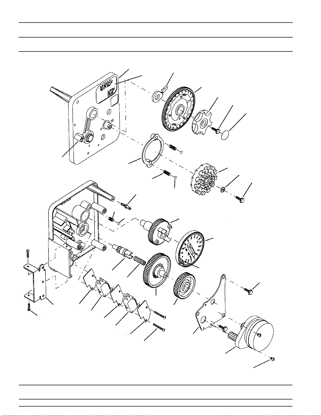
MODEL 3200 TIMER
Timer Assembly
(See opposite page for parts list)
130 2
3456
785
29 31
10
11
9
13
14
15
5
12 32
16 17
18
19
20
21
22
23
24 25 26 25 27 25 28

Printed in U.S.A.
Page 17
MODEL 3200 TIMER
Timer Assembly
Parts List
Item No. Quantity Part No. Description
1 . . . . . . . . . . . 1 . . . . . . . . . . . 13870 . . . . . . . . . . . . . . . Timer Housing
2 . . . . . . . . . . . 1 . . . . . . . . . . . 13011 . . . . . . . . . . . . . . . Cycle Actuator Arm
3 . . . . . . . . . . . 1 . . . . . . . . . . . 40096-24. . . . . . . . . . . . . 24 Hour Gear Assembly, 12 Midnight
40096-02. . . . . . . . . . . . . 24 Hour Gear Assembly, 2 a.m.
4 . . . . . . . . . . . 1 . . . . . . . . . . . 13886-01. . . . . . . . . . . . . Knob
5 . . . . . . . . . . . 5 . . . . . . . . . . . 13296 . . . . . . . . . . . . . . . Screw - Timer Knob and Motor Mtg. Plate
6 . . . . . . . . . . . 1 . . . . . . . . . . . 11999 . . . . . . . . . . . . . . . Button Decal
7 . . . . . . . . . . . 1 . . . . . . . . . . . 14381 . . . . . . . . . . . . . . . Skipper Wheel Assembly - 12 Day
14860 . . . . . . . . . . . . . . . Skipper Wheel Assembly - 7 Day
8 . . . . . . . . . . . 1 . . . . . . . . . . . 13014 . . . . . . . . . . . . . . . Regeneration Pointer
9 . . . . . . . . . . . 1 . . . . . . . . . . . 14265 . . . . . . . . . . . . . . . Spring Clip
10 . . . . . . . . . . 2 . . . . . . . . . . . 13311 . . . . . . . . . . . . . . . Spring - Skipper Wheel Detent
11 . . . . . . . . . . 2 . . . . . . . . . . . 13300 . . . . . . . . . . . . . . . Ball - 1/4 in. Dia. Skipper Wheel
12 . . . . . . . . . . 1 . . . . . . . . . . . 15424 . . . . . . . . . . . . . . . Spring - Main Gear Detent
13 . . . . . . . . . . 1 . . . . . . . . . . . 13911 . . . . . . . . . . . . . . . Main Drive Gear
14 . . . . . . . . . . 1 . . . . . . . . . . . 19210 . . . . . . . . . . . . . . . Program Wheel
15 . . . . . . . . . . 21 . . . . . . . . . . 15493 . . . . . . . . . . . . . . . Roll Pin
16 . . . . . . . . . . 1 . . . . . . . . . . . 13018 . . . . . . . . . . . . . . . Idler Shaft
17 . . . . . . . . . . 1 . . . . . . . . . . . 13312 . . . . . . . . . . . . . . . Spring - Idler
18 . . . . . . . . . . 1 . . . . . . . . . . . 13017 . . . . . . . . . . . . . . . Idler Gear
19 . . . . . . . . . . 1 . . . . . . . . . . . 13164 . . . . . . . . . . . . . . . Drive Gear
20 . . . . . . . . . . 1 . . . . . . . . . . . 13887 . . . . . . . . . . . . . . . Motor Mounting Plate
21 . . . . . . . . . . 1 . . . . . . . . . . . 18743 . . . . . . . . . . . . . . . Motor - 120V., 60 Hz.
19659 . . . . . . . . . . . . . . . Motor - 24V., 60 Hz.
22 . . . . . . . . . . 2 . . . . . . . . . . . 13278 . . . . . . . . . . . . . . . Screw - Motor Mounting
23 . . . . . . . . . . 3 . . . . . . . . . . . 11384 . . . . . . . . . . . . . . . Screw - Timer Hinge & Ground Wire
24 . . . . . . . . . . 1 . . . . . . . . . . . 13881 . . . . . . . . . . . . . . . Hinge Bracket
25 . . . . . . . . . . 3 . . . . . . . . . . . 14087 . . . . . . . . . . . . . . . Insulator
26 . . . . . . . . . . 1 . . . . . . . . . . . 10896 . . . . . . . . . . . . . . . Switch
27 . . . . . . . . . . 1 . . . . . . . . . . . 15320 . . . . . . . . . . . . . . . Switch
28 . . . . . . . . . . 2 . . . . . . . . . . . 11413 . . . . . . . . . . . . . . . Screw - Switch Mounting
29 . . . . . . . . . . 1 . . . . . . . . . . . 14007 . . . . . . . . . . . . . . . Decal - Time of Day
30 . . . . . . . . . . 1 . . . . . . . . . . . 14045 . . . . . . . . . . . . . . . Decal - Instructions
31 . . . . . . . . . . 1 . . . . . . . . . . . 13864 . . . . . . . . . . . . . . . Skipper Wheel Ring
32 . . . . . . . . . . 1 . . . . . . . . . . . 15066 . . . . . . . . . . . . . . . Ball 1/4 in. Dia. Main Gear
Not Shown. . . . 1 . . . . . . . . . . . 13902 . . . . . . . . . . . . . . . Harness
Not Shown. . . . 2 . . . . . . . . . . . 12681 . . . . . . . . . . . . . . . Wire Connector
Not Shown. . . . 1 . . . . . . . . . . . 15354-01. . . . . . . . . . . . . Ground Wire

Printed in U.S.A.
Page 18
1600 Series Brine System Assembly
Item No. Quantity Part No. Description
1. . . . . . . . . . . 1 . . . . . . . . . . . . .10328. . . . . . . . . . . . . 90°Elbow - 1/4 Pipe Thd. to 3/8 Tube
2. . . . . . . . . . . 1 . . . . . . . . . . . . .12767. . . . . . . . . . . . . Brine Line Screen
3. . . . . . . . . . . 3 . . . . . . . . . . . . .10332. . . . . . . . . . . . . Insert Sleeve (3/8 Tube)
4. . . . . . . . . . . 3 . . . . . . . . . . . . .10329. . . . . . . . . . . . . Fitting Nut (3/8 Tube)
5. . . . . . . . . . . 3 . . . . . . . . . . . . .10330. . . . . . . . . . . . . Delrin Sleeve (3/8 Tube)
6. . . . . . . . . . . 1 . . . . . . . . . . . . .12774. . . . . . . . . . . . . Brine Valve Tube
7. . . . . . . . . . . 1 . . . . . . . . . . . . .60002. . . . . . . . . . . . . Air Check Assembly
8. . . . . . . . . . . 1 . . . . . . . . . . . . .12794. . . . . . . . . . . . . 90°Elbow - 3/8 Tube to 3/8 Tube
9. . . . . . . . . . . 1 . . . . . . . . . . . . .Not Supplied. . . . . . . . Brine Line Tube (3/8 Flexible Tube)
10. . . . . . . . . . . 1 . . . . . . . . . . . . .10250. . . . . . . . . . . . . Retaining Ring
11. . . . . . . . . . . 1 . . . . . . . . . . . . .11749. . . . . . . . . . . . . Stem Guide
12. . . . . . . . . . . . . . . . . . . . . . . . . . . . . . . . . . . . . . . . . . . . Not Assigned
13. . . . . . . . . . . . . . . . . . . . . . . . . . . . . . . . . . . . . . . . . . . . Not Assigned
14. . . . . . . . . . . 1 . . . . . . . . . . . . .10249. . . . . . . . . . . . . Brine Valve Spring
15. . . . . . . . . . . 1 . . . . . . . . . . . . .12550. . . . . . . . . . . . . Quad Ring
16. . . . . . . . . . . 1 . . . . . . . . . . . . .12748. . . . . . . . . . . . . Brine Valve Body
1 . . . . . . . . . . . . .15902 . . . . . . . . . . . . . Brine Valve Body — 1500SM
17. . . . . . . . . . . 1 . . . . . . . . . . . . .12552. . . . . . . . . . . . . Brine Valve Stem
18. . . . . . . . . . . 1 . . . . . . . . . . . . .12626. . . . . . . . . . . . . Brine Valve Seat
19. . . . . . . . . . . 1 . . . . . . . . . . . . .11982. . . . . . . . . . . . . O-Ring
*20. . . . . . . . . . . 1 . . . . . . . . . . . . .12747. . . . . . . . . . . . . Flow Control Fitting
*21. . . . . . . . . . . 1. . . . . . . . . . . . . . . . . . . . . . . . . . . . . . . . Flow Control Label — (Specify Flow Rate)
*22. . . . . . . . . . . 1. . . . . . . . . . . . . . . . . . . . . . . . . . . . . . . . Flow Control Washer — (Specify Flow Rate)
*23. . . . . . . . . . . 1 . . . . . . . . . . . . .12098. . . . . . . . . . . . . Flow Control Retainer
* These Parts Are Furnished Assembled Together As A Brine Line Flow Control (BLFC).
1
2
3
456
7
8
9
10 11
14
15
16
17
18
19
20 - 21
22
23
45
3
5
4
PARTS LIST

Printed in U.S.A.
Page 19
MODEL 2500 & 1500
Service Instructions
PROBLEM CAUSE CORRECTION
1. Softener fails to regenerate. A. Electrical service to unit has been
interrupted.
B. Timer is defective.
C. Power Failure
A. Assure permanent electrical service
(check fuse, plug, pull chain or
switch).
B. Replace timer.
C. Reset Time of Day.
2. Hard water. A. By-pass valve is open.
B. No Salt in Brine Tank.
C. Injector screen plugged.
D. Insufficient water flowing into brine
tank.
E. Hot water tank hardness.
F. Leak at distributor tube.
G. Internal valve leak.
A. Close by-pass valve.
B. Add salt to brine tank and maintain
salt level above water level.
C. Clean injector screen.
D. Check brine tank fill time and clean
brine line flow control if plugged.
E. Repeated flushing of the hot water
tank is required.
F. Make sure distributor tube is not
cracked. Check O-Ring and tube
pilot.
G. Replace seals and spacers and/or
piston.
3. Unit used too much salt. A. Improper salt setting.
B. Excessive water in brine Tank.
A. Check salt usage and salt setting.
B. See problem no. 7.
4. Loss of water pressure. A. Iron buildup in line to water
conditioner.
B. Iron buildup in water conditioner.
C. Inlet of control plugged due to
foreign material broken loose from
pipes by recent work done on
plumbing system.
A. Clean line to water conditioner.
B. Clean control and add mineral
cleaner to mineral bed. Increase
frequency of regeneration.
C. Remove piston and clean control.
5. Loss of mineral through drain line. A. Air in water system. A. Assure that well system has proper
air eliminator control. Check for dry
well condition.
6. Iron in conditioned water. A. Fouled mineral bed. A. Check backwash, brine draw and
brine tank fill. Increase frequency of
regeneration. Increase backwash
time.

Printed in U.S.A.
Page 20
MODEL 2500 & 1500
Service Instructions (Cont’d.)
7. Excessive water in brine tank. A. Plugged drain line flow control.
B. Plugged injector system.
C. Timer not cycling
D. Foreign material in brine valve.
E. Foreign material in brine line flow
control.
A. Clean flow control.
B. Clean injector and screen.
C. Replace timer.
D. Replace brine valve seat and clean
valve.
E. Clean brine line flow control.
8. Softener fails to draw brine. A. Drain line flow control is plugged.
B. Injector is plugged.
C. Injector screen plugged.
D. Line pressure is too low.
E. Internal control leak.
A. Clean drain line flow control.
B. Clean injector.
C. Clean screen.
D. Increase line pressure to 20 P.S.I.
E. Change seals, spacers and piston
assembly.
9. Control cycles continuously. A. Broken or shorted switch A. Determine if switch or timer is faulty
and replace it, or replace complete
power head.
10. Drain flows continuously. A. Valve is not programing correctly.
B. Foreign material in control.
C. Internal control leak.
A. Check timer program and positioning
of control. Replace power head
assembly if not positioning properly.
B. Remove power head assembly,
and inspect bore, remove foreign
material and check control in
various regeneration positions.
C. Replace seals and piston
assembly.
PROBLEM CAUSE CORRECTION
This manual suits for next models
1
Table of contents
Other Addie Water Systems Water Dispenser manuals

Popular Water Dispenser manuals by other brands


Elkay
Elkay FLEXI-GUARD EFHA8, 14 1F Series Installation, care & use manual

Conrad
Conrad Thermaltake PW850i operating instructions

Hasley Taylor
Hasley Taylor 4400BF owner's manual

DS Services of America
DS Services of America Pure Water Dispenser 100 Series How to Clean

NaturalSof
NaturalSof NS05 instruction manual

WaterLogic
WaterLogic WL400 Series manual


