ADDIMP 3D CURTISS H-75 User manual

ADDIMP 3D
Une création originale ADDIMP 3D
CURTISS H-75
Assembly userguide
ADDIMP 3D Original
Version 1.0

ADDIMP 3D
Une création originale ADDIMP 3D
This model reproduces the Curtiss Hawk H-75 in these two versions A-1 to A-3 and A-4 / A-5 for
manufacturing in 3D printing.
It is your responsibility to manufacture all of the parts necessary for the construction of this model.
All files are provided in stl format, compatible with the majority of slicers softwares in the 3D
printing market.
1- History
The Curtiss H-75 Hawk was developed in the USA in the mid-1930s on the basis of the Curtiss P-36.
It was of the same generation as the Hawker Hurricane and Messerschmitt Bf 109. It was then part
of the generation of modern single-plane fighters, of all-metal construction.
The Model 75 was designed by engineer Donovan Berlin using Curtiss' own funds. The first
prototype was assembled in 1934, it was equipped with a 900 hp Wright XR-1670-5 engine and an
armament consisting of a 7.62 mm machine gun and another 12.7 mm, pulling through the
propeller disc. The landing gear was half embedded in the wing and rotated 90 °.
The prototype made its initial flight in May 1935, reaching 452 km / h at 10,000 feet (3,050 m) from
the first flights. He was escorted to Wright Field in May 1935 to participate in a competition
organized by the USAAC to choose his future fighter. The contest was postponed due to an accident
of the contestant proposed by Seversky. Curtiss took the opportunity to replace the engine with a
950 hp Wright XR-1820-39 Cyclone and to rework the fuselage.
The competition finally took place in April 1936. Unfortunately, the plane did not exceed 460 km/h,
the new engine being unable to provide the necessary power. The Seversky P-36, although more
expensive than the Curtiss fighter, and also showing disappointing performance, was still declared
the winner and ordered by the USAAC.
With the European context deteriorating very quickly, the USAAC feared that Seversky would be
unable to deliver his aircraft on time and decided to acquire a second fighter model. In June 1936
Curtiss received an order for three prototypes, designated Y1P-36. The new aircraft, designated
Model 75E, was powered by a 900 hp Pratt & Whitney R-1830-13 Twin Wasp and a canopy with
further improved rear visibility. His performance was such that he won the 1937 competition of the
USAAC, which ordered two hundred and ten P-36A fighters. The export version is designated H-75.
Obsolete even before the start of the Second World War, it was used by the British Commonwealth
(Mohawk), Argentina, Brazil, China, Finland, France, Iran, Norway, the Netherlands, Peru, Portugal
and Thailand. Over a thousand planes were built.

ADDIMP 3D
Une création originale ADDIMP 3D
2- Caracteristics
scale ~ 1:12
Length : H-75A-1 / A-3 : 676 mm , H-75A-4 / A-5 : 666 mm
Wingspan : 950 mm
Surface : 15.2 dm²
Weight of the 3D printed parts with std PLA : ~750g,
Inflight weight between 1000 and 1300 g, as per equipment
Wing loading : entre 70 et 90 g/dm²
Center of gravity at 52 mm from the leading edge at root.
Construction skill
Experience with building some wood or fiber kits
Flying skill
Flying experience like aerobatic aircraft
Versions History
Version 1.0
2021, january
First Version

ADDIMP 3D
Une création originale ADDIMP 3D
3- Content of the pack
L’ensemble des fichiers STL, ainsi que les fichiers factory (Simplify 3D) et G-Codes
This version can be made for 3 channels ; aileron, elevator and engine, or 4 channels (+ rudder).
There are two variants, the Wright R-1830 engine version, type A-1 to A-3 with the rounded engine cover
and the Wright R-1820 engine version, type A-4 and A-5 with the more angular engine cover.
H-75 A-1 to A-3
H-75 A-4 and A-5

ADDIMP 3D
Une création originale ADDIMP 3D
4- Balance
5- Material and equipment
All the parts could be printed on a 200 x 200 x 200 mm volume 3D printer with a 0.4 mm nozzle.
The slicer is Simplify 3D. Factory and G-code files are provided for 1.75mm diameter PLA filament. All parts
require less than 0.75kg of PLA.
A profile for Simplify 3D is proposed as exemple in the directory ../factory (MK3PLA-3DP.fff)
The design is also compliant with the use of PETG, LW-PLA or LW-ASA.
Equipment :
-Brushless motor between 250 and 300 W, example :
o3S :
▪engine Pro-tronick DM 2810 - 950 kV
▪engine Roxxy C3542 –810 kV
oESC 30 A to 50 A
oBattery LiPo 3S - 1800 à 2200 mA –45C, dimensions maxi : L 140 x l 55 x h 55 mm
Pay attention to the connectors between the ESC and the battery.
Center of gravity at 52mm
Recess for balance

ADDIMP 3D
Une création originale ADDIMP 3D
-It is possible to use powerplant with 4s or 6s. This type of sports engine is intended for experienced
model builders and will not be the subject of any particular recommendation.
Equipment
-3 or 4 servos 9 to 16 g type Savox SH-0255 MG or HXT900
-2x rubber band 120 x 10 mm or 1x nylon screw + nut M6 (option for wing fixture)
-Wire pushrod Ø0.8 or Ø1mm for elevator and rudder
-Wire pushrod Ø 1.5 for ailerons
-Ø2mm carbon rod for the hinges
-glue CA medium
-1x Velcro strap length 200 mm
-2x servo extension cable for aileron, length 150 mm minimum.
-Option ;
o1 carbon tube Ø3 mm x 500 mm for the wing spare (length should be adjust in place)
o2x Ø1mm carbon rod for the rear fuselage
-2x self-tapping screw Ø3 x 20 (motor mount)
All accessories could be found at : http://www.rcjetshobby.com/fr/10000493-sets-addimp-3d
Pro-tronik motors: http://www.rcjetshobby.com/fr/10000450-pro-tronik
Pro-tronik ESC: http://www.rcjetshobby.com/fr/81-controleurs
6- Paramètres d’impression
!! the use of the LW-PLA from Colorfab is explain in a specific file in the factory directory !!
Few quantity of parts needs special parameters, they are describe when needed.
G-Codes are based on Prusa Mk3 & Mk 3S, Ø1.75mm PLA.
The use with other 3D printer or filament will have different results. Even in the same brand of filament,
color may change results.
As often as possible use the factory files to adapt to your 3D printer and your filament.
Example of parameters :
Nozzle diameter = 0.4 mm
General layer thickness = 0.25 mm
Extrusion width = 0.42 mm
Default printing speed = 60 mm/s
1st layer thickness = 80% or 0.2 mm
1st layer width = 105%

ADDIMP 3D
Une création originale ADDIMP 3D
1st layer speed = 50 to 66%
Retraction distance, depend of the filament, ~ 1 to 2 mm, to be adjust
Retraction speed = 30 mm/s
Extra restart distance (distance to begin extrusion before printing the part) = 0.05 to 0.1 mm
Vertical lift (avoid collision between nozzle & part during travel moves) = 0.4mm
Possible wipe option activated, may replace a part of retraction.
Temperatures
-Bed = 55 to 60° C
-Extruder = 220 to 230 °C (best layer adhesion)
-No cooling, except for the tips (~20%)
7- H-75 –décomposition :
Part
Qtty
weight
(g)
Comment
STL name
factory file & G-code name
Fuselage A1 / A3
F1
1
H-75A1-1_12-F1
H-75A-1-1_12-F1
Battery hatch
1 + 1
H-75A1-1_12-hatch-front
H-75A1-1_12-hatch-rear
H-75A-1-1_12-Hatch
Fuselage A4 / A5
F1
1
H-75A4-1_12-F1
H-75A-4-1_12-F1
Battery hatch
1 + 1
H-75A4-1_12-hatch-front
H-75A4-1_12-hatch-rear
H-75A-4-1_12-Hatch
Fuselage common
fishplate F1 / F2
2
H-75-1_12-F1-F2-eclisse
../accessoires/H-75-1_12-
pieces-PLA
F2
1
H-75-1_12-F2
H-75-1_12-F2
F3
1
H-75-1_12-F3
H-75-1_12-F3
F4
1
H-75-1_12-F4
H-75-1_12-F4
Elevator cap
1
H-75-1_12-F4-stab-cover
Canopy
1
Can be printed
with clear PLA
H-75-1_12-canopy
H-75-1_12-canopy
lock
1
hatch-lock
../accessoires/H-75-1_12-
pieces-PLA

ADDIMP 3D
Une création originale ADDIMP 3D
Lock housing
1
H-75-1_12-lock-housing
Wing
W1L / R
1
Symetrics,
H-75-1_12-W1L
H-75-1_12-W1R
H-75-1_12-W1L
H-75-1_12-W1R
W2L / R
1
Symetrics,
H-75-1_12-W2L
H-75-1_12-W2R
H-75-1_12-W2LR
W3L / R
1
Symetrics,
H-75-1_12-W3L
H-75-1_12-W3R
H-75-1_12-W3LR
W3L / R tip hinge
1
Symetrics,
H75-1_12-W3L-TE-hinge
H75-1_12-W3R-TE-hinge
Aileron L
1 + 1
H75-1_12-aileron-G-ext
H75-1_12-aileron-G-int-sans-tab
H75-1_12-ailerons
Aileron R
1 + 1
H75-1_12-aileron-D-ext
H75-1_12-aileron-D-int-avec-tab
Wing fairing
1 + 1
H-75-1_12-Belly-front
H-75-1_12-Belly-rear
Gear cover
1 + 1
Symetrics,
H75-1_12-W1L-bossage-train-Av
H75-1_12-W1L-bossage-train-Ar
H75-1_12-W1LR-bossages-
trains
Leading edges
1 + 1
3 versions, lisse, 1
ou 2 trous
H75-1_12-WR-BA-lisse
H75-1_12-WR-BA-1_gun
H75-1_12-WR-BA-2_guns
Tails
Horizontal tail
1 + 1
Symetrics
H-75-1_12-H-stab-D
H-75-1_12-H-stab-G
H-75-1_12-H-stab
Tip
1 + 1
Symetrics
H-75-1_12-h-stab-D-saumon
H-75-1_12-h-stab-G-saumon
elevator
1 + 1
Symetrics
H-75-1_12-H-volet-D-int
H-75-1_12-H-volet-D-mid
H-75-1_12-H-volet-D-ext
H-75-1_12-H-elevators
Elevator control horn
1 + 1
Symetrics
H-75-1_12-H-stab-D-raccord
H-75-1_12-H-stab-G-raccord
../accessoires/H-75-1_12-
pieces-PLA
Vertical fin
1
H-75-1_12-V-stab-fixe
H-75-1_12-V-stab
Rudder (2x)
4
H-75-1_12-Rudder-D1-2X
H-75-1_12-Rudder-D2-2X
H-75-1_12-Rudder-D3
H-75-1_12-Rudder-D4
H-75-1_12-Rudder-2x
Rudder (3x)
4
H-75-1_12-Rudder-D1-3X
H-75-1_12-Rudder-D2-3X
H-75-1_12-Rudder-D3
H-75-1_12-Rudder-D4
H-75-1_12-Rudder-3x
Accessories
../ motors-mounts
Supports
1_12-MM-« length of motor »-
« screw pattern »
1_12-MM-Template

ADDIMP 3D
Une création originale ADDIMP 3D
Hinges
elevator
2
hinge-court-D2x15x5
../accessoires/H-75-1_12-
pieces-PLA
Aileron
2
hinge-court-D2x15x6_4
rudder
2
hinge-long-D2x15x5
1
hinge-court-D2x15x5
Servo mount L / R
1 + 1
symetrics
support_D_servo-mini
couvercle-D-servo-aile
servo-mount_16g-LR
8- wings
8.1- Contrôler toutes les pièces
First, check all the parts, remove all the residual skirt, to sand if needed the parts. Check that all hinge
housings are clean and open.
Assemble all the parts without any glue, to check the well adjustment and alignement.
If you use the carbon tube option, check that it slides freely in its housing.
Then glue each section together, beginning by root section, L1 with L2, then L3. Same order for the right
wing.
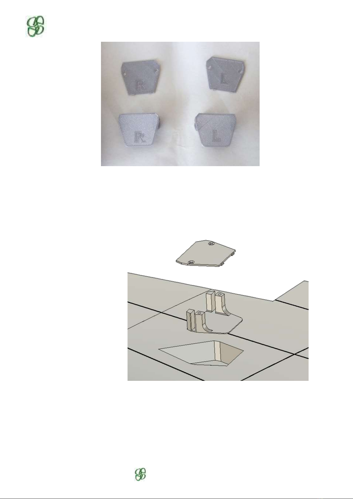
8.2- Support servo
To facilitate the mount and setup of the servo, it is used a special mount with cover. Each part is labelled
with « R » for right side and « L » for left side
W2
W1
W3
ADDIMP 3D
Une création originale ADDIMP 3D
First, glue the mount to the wing. Each one have a letter to indicate the side (L for the left wing, R for right
wing). You can use a servo to keep it straight.
Then fit the servo on the bay, adjust the linkage to the aileron easily, once finish, screw the cover to the
mount with 2 screws 2 x 10.
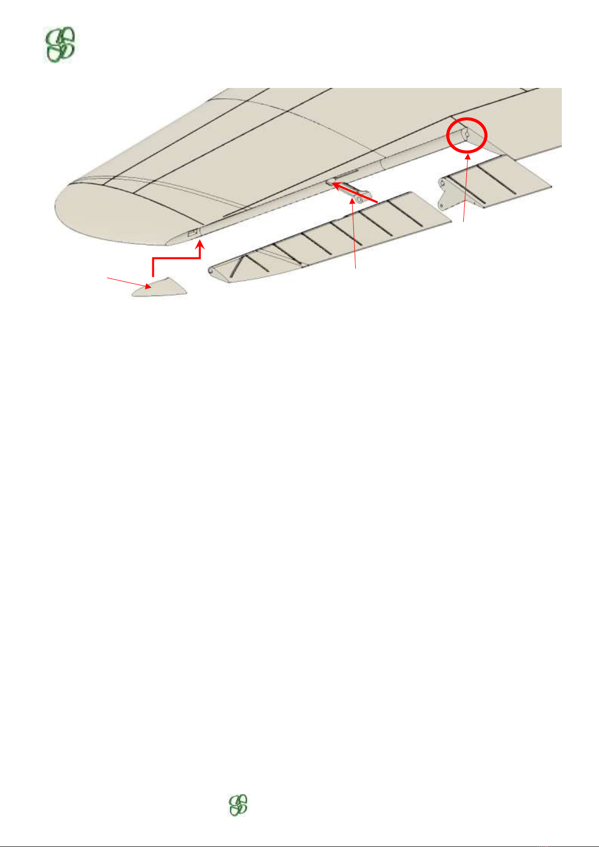
Install the aileron, check all the passage holes of the hinge pin, glue the 2 parts of the aileron together.
On the wing, there is 1 Ø2 x 15 x 6.4 hinge to present and adjust. Do not stick it.
Installation
W2L
W1L
ADDIMP 3D
Une création originale ADDIMP 3D
Present the aileron with its axis on the assembly, adjust the constant clearance between the wing and the
aileron, then glue the hinges to the wing.
Then assemble the two parts of the wing. Do not forget the Ø3mm carbon tube if necessary
(recommended for LW and PETG filaments).
Do not glue the lower wing fairings at this time.
Hole for the axis
Hinge width 6.4mm
Tip hinge

ADDIMP 3D
Une création originale ADDIMP 3D
9- Fuselage
Assembly diagram, for details, see following pages.
Check all the control passage ducts, a Ø2mm rod must slide freely.
F1
•check the two servo housings and the wire passages
•check the two fishplate housings
•install the velcro strap
F2 to F4
•check the two fishplate housings in F2
•check the nut seat in F3 (if used)
•check the correct fit of each section, then glue them together with F1, in the
order of the sections.
•possibility of adding 2 Ø1mm rods in F3 and F4 to stiffen the rear (LW filament)
Fin
•check all the hinge points, adjust if necessary
•glue the fixed fin part
H stab
•check all the shaft passages in the elevator and hinges (Ø2mm carbon rod)
•assemble the three parts of the elevator together
•install the elevator pushrod in the fuselage and connect it to the horn
•assemble the left stab then the right on the fuselage
Rudder
•glue the cap in F4 to hide the elevator horn
•check all the shaft passages in the rudder and the hinges (Ø2mm carbon rod)
•assemble the four parts of the rudder together
•install the rudder pushrod (if used) in the fuselage and connect it to the horn
•install the hinges in the rudder with the carbon axis
•glue the hinges into the fuselage

ADDIMP 3D
Une création originale ADDIMP 3D
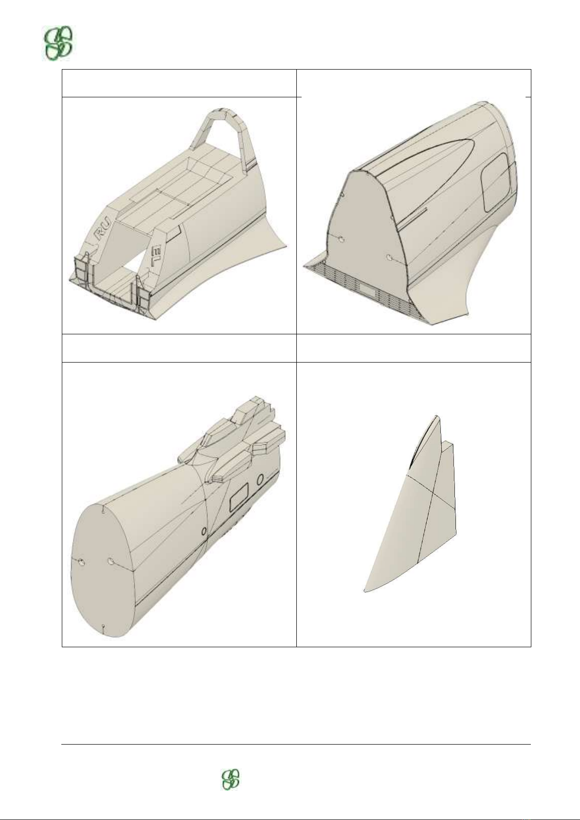
Version A1 to A3
F1
Battery hatch
Version A4 & A5
F1
Battery hatch
ADDIMP 3D
Une création originale ADDIMP 3D
F2
F3
F4
Fin
ADDIMP 3D
Une création originale ADDIMP 3D
Horizontal Stabilizer
Rudder

ADDIMP 3D
Une création originale ADDIMP 3D
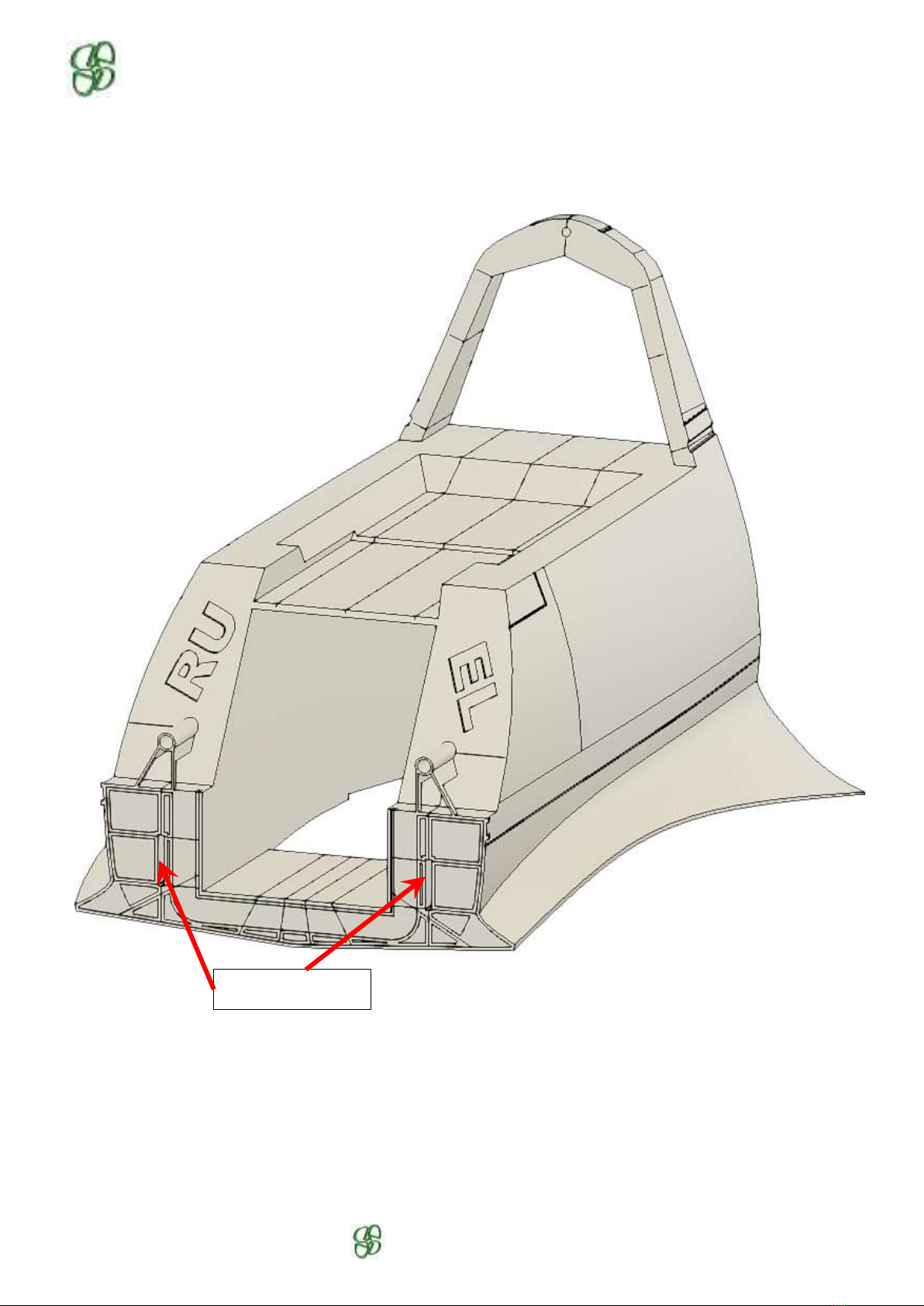
9.1- F1 Preparation
Check the two servo housings and the electrical wire passages.
Check the two fishplate housings.
Install the strap for the battery, provide hook-and-loop strips in the bottom of the battery compartment.
Battery strap
Fishplate housings
ADDIMP 3D
Une création originale ADDIMP 3D
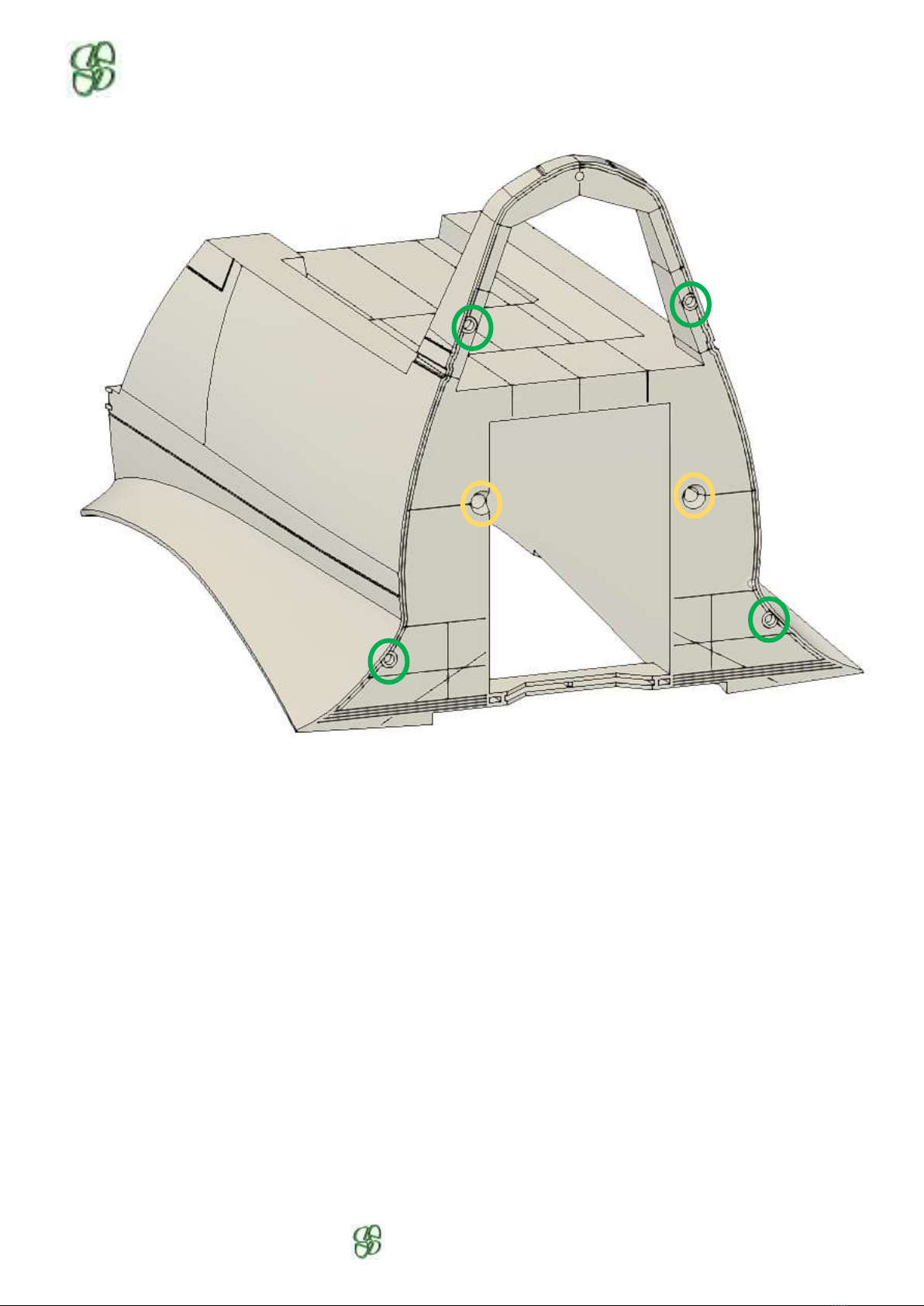
9.2- F2 Preparation
Check the two fishplate housings.
Fishplates housings
ADDIMP 3D
Une création originale ADDIMP 3D
Check the pushrod passages (yellow circles) and the 4 holes for centering (green circles).

ADDIMP 3D
Une création originale ADDIMP 3D
9.3- Préparation de F3
Check the pushrod passages (yellow circles), the 4 holes for centering (green circles) and the 2 housings for
the Ø1mm carbon rod (blue circles).
The centering of the sections F3 and F4 is effected by peripheral ribs. Check that they are in good condition
when printed as well as that of the receptacle part in the adjacent section.
Open the lower area if using rubber bands, otherwise, drill a Ø7mm hole for
the screw to pass
Check the nut housing if used

ADDIMP 3D
Une création originale ADDIMP 3D
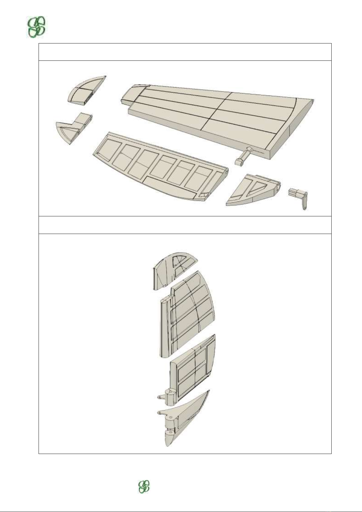
10-Horizontal Stabilizer
Use CA glue for assembly,
Check the passage of the Ø2 mm rod in all the hinge pin holes and the bearings / horn. The length of the
axle is 300mm
Hinge length 5mm
Passages d’axe carbone
Table of contents


