Adel System CB304A User manual

A
AD
DE
EL
L
s
sy
ys
st
te
em
m
Instruction Manual Instruction Manual CB304A_R05 Eng
ADEL system srl Via L. Barchi 9/B, 42124 Reggio Emilia (Italy) –Tel. ++39-0522-345518
Fax. ++39-0522-345551 –Internet: www.adelsystem.com
CB304A (15 Cells Pb-Gel, 25 Cells Ni-Cd)
Intelligent Battery Charger
Thank you for having chosen one of our products for your work. We are certain
that it will give the utmost satisfaction and be a notable help on the job.
•General Description:
Application
CB battery charger is a range of microprocessor-power supplies witch correctly charge open or sealed
lead-acid batteries, Gel batteries and Ni-Cd batteries at all-time maximizing performance and life span.
Charge the battery in multi-stage principle, Fast and Trickle and automatically the device check the battery
quality in a lifetime to prevent any risk of damage to the battery and allow leaving the charger permanently
connected. Before begin the operations of installation consult the manual.
•Mains Characteristic
•Nominal Input Voltage: 115 - 230 -277Vac
•OUTPUT 1: for connection to Battery
•Fast and trickle battery charge In according to DIN 41773
•Signalling: fault status of the battery
•Overload and short circuit protections
•Power limited Battery output
•Safety isolation in according with EN 60950
•Degree of protection IP20
•Rail DIN mounting
Vac Input
Charging Level
OUTPUT N°1
Battery module
OUTPUT N°1
Battery module
OUTPUT N°1
Battery module
OUTPUT N°1
Battery module
OUTPUT N°1
Battery module
OUTPUT N°1
Battery module
OUTPUT N°1
Battery module
OUTPUT N°1
Battery module
OUTPUT N°1
Battery module
OUTPUT N°1
Battery module
OUTPUT N°1
Battery module
OUTPUT N°1
Battery module
OUTPUT N°1
Battery module
OUTPUT N°1
Battery module
OUTPUT N°1
Battery module
OUTPUT N°1
Battery module
Fault Status
Battery Type
Configuration Jumper
Monitor Led:
•Fault
•Diagnosis
_________________________________________________________Battery Charger
All specification are subject to change without notice
INSTRUCTION MANUAL 2
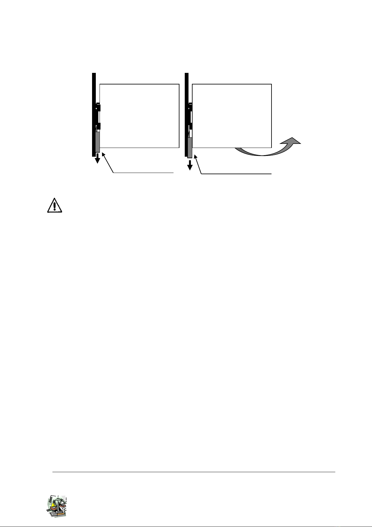
Rail mounting:
•The module must be mounted in vertical position.
•Other modules must have a minimum vertical distance of 10 cm to this power supply in order to
guarantee sufficient auto convection.
•Mounting scheme:
Caution: Switch off the system before connecting the module. Never work on the machine when
it is live.
Functional Characteristics
Charging Level Current: With trimmer from 20% to 100% of In. Select the max. battery charge current
estimated from 10 to 30% of the nominal capacity
Battery Module (Output 1) 1-2 Pin: Battery input.
Low Battery or Battery replacement: In normal condition with battery in good status:
led fault off and contact close (3-4),
Any fault status of the battery: led fault on and contact open (3-4)
Diagnosis LED
•Normal conditions:
oVery fast blinking = recovery charging ( when the battery is too low, Under 30 Vdc)
oFast blinking = fast charge
oSlow blinking = trickle charge (floating charge)
•Error conditions, Led Fault on and Led Diagnosis:
o1 blinking = Battery Reverse polarity battery; Bad input voltage battery.
o2 blinking = Battery not connected.
o3 blinking = Short circuit battery element
o5 blinking = Bad battery.(Internal impedance Bad or Bad battery wire connection)
Assembly: pull down the plastic block with
a screwdriver, place the CB on the rail and
release the plastic block.
The CB is now assembled on the rail.
Disassembly: pull down the plastic block and pullout
the module like the arrow in the scheme
_________________________________________________________Battery Charger
All specification are subject to change without notice
INSTRUCTION MANUAL 3
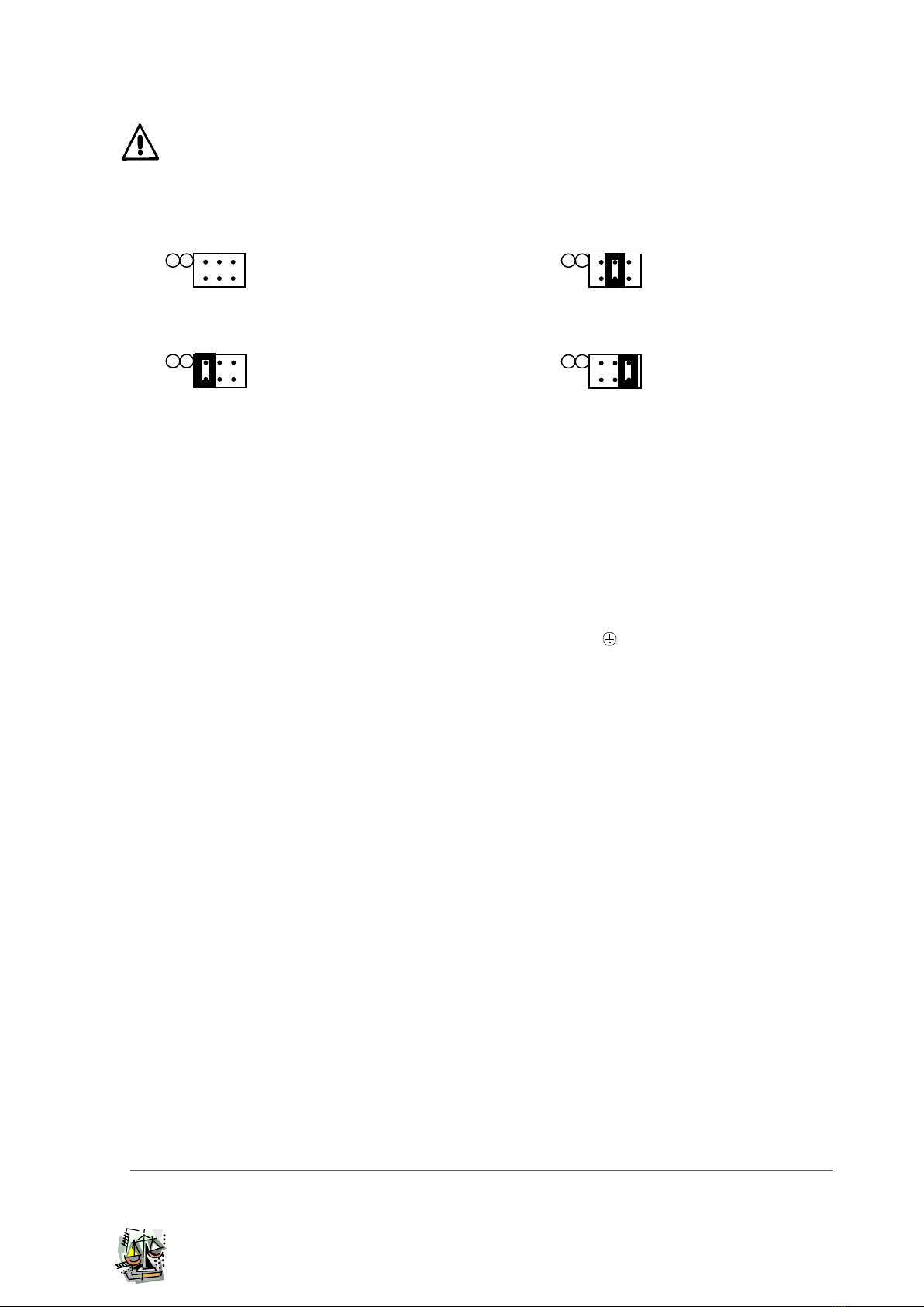
•Battery Type Configurations
Caution:
Switch off the system before setting the
jumper.
Jumper positions for charging:
0. Open Lead (Charge): Trickle =2.23 Fast=2.40/cell
1. Sealed Lead (Charge): Trickle =2.25 Fast=2.40/cell
N.B. 15 cells Lead Battery or Gel Battery.
2. Gel Battery (Charge):Trickle =2.30 Fast=2.40/cell
3. Ni-Cd Battery (Charge): Trickle =1.35 Fast=1.50/cell
N.B. 25 cells Ni-Cd Battery.
Notice:
For Ni-Cd Battery the End-of-charge is the detection of “flat” profile. If flat profile is detected fast
charge is terminated after 2 hours. General end-of-charge timeout set to 16 hours. Trickle charge
is pulsed with a duty cycle of 2% (20msec/sec). Charging current must be set at least at 30% of
nominal battery capacity (0,3 C).
•Cable connection
The following cable cross-sections may be used:
At the Input: 0.2÷2.5 mm2 rigid / flexible
At the Output: 0.2÷2.5 mm2 rigid / flexible
Strip the connection ends: 7mm
Input: The input connection is made by the screw connections L, N, PE .
•Protection
On the primary side: the device is equipped whit a internally fuse T 4 A/250Vac. If the internal fuse is
activated, it is most probable that there is a fault in the device. If happen, the
device must be checked in the factory
On the secondary side Battery and load: The device is electrically protected against short circuits and
overload.
Inversion polarity: the module is protected against inversion of battery polarity.
Over current and output short circuit: the unit limits the output power at max. 108W in normal rating.
Battery Test: Automatic. Check polarity and battery. Every 4 hours in trickle charge, make the test of the
battery quality. The fault is signalized with relay commutation and diagnosis led blinking.
Characteristic curve
•Output current
Internal temperature is electronically controlled. Therefore, battery current is continuous as long as
temperature does not exceed the established limit.
Short circuit and overload
The output current to the battery is selected with the Charge Level trimmer. The maximum power –load
of 108W limits the current to the battery, in 187-264 Vac input range. In 93-132 Vac input range it is
necessary to consider the derating of 60 W max specified in technical features.
Thermal behavior
The device supplies the nominal output current at ambient temperature of up 40°C. For ambient
temperature of over 40°C, the output current must be reduced by 1% per °C increase in temperature. Max
50°C.
1
2
3
Battery
Type
1
2
3
Battery
Type
1
2
3
Battery
Type
1
2
3
Battery
Type

_________________________________________________________Battery Charger
All specification are subject to change without notice
INSTRUCTION MANUAL 4
•Standards and Certifications
Electrical safety
The device must be installed in according with EN60950. The device must have a suitable isolating facility
outside the power supply unit, via which can be switched to idle. Sicurezza EN IEC 62368-1
General Standard
Immunity in according with EN50082-2, level 3, class B
Radio interference suppression in according with EN 55011 class A (industrial areas)
Input Data
Nominal Input Voltage (2 x Vac)
115 –230 -277Vac
Input voltage range
90 ÷ 305 Vac
Inrush Current (Vn –In)
16 5 msec.
Frequency
47 ÷ 63 Hz
Input Current (Nominal input Voltage)
2.4 –1.2 A
Internal Fuse
4 A
External Fuse (recommended)
6 A
Output Data
Output Voltage Battery Bulk Charge / Nominal Current
Max: 36 V Pb 37,5V Ni-Cd
Output Voltage Battery Trickle Charge / Nominal Current
Max: 34.5 V Pb 33,75V Ni-Cd
Charging. Max Ibatt < 40°C (In)
4 A
Charging. Max Ibatt > 40°C (In)
3 A
Adjustment range of charge (In adj)
20 ÷ 100% In
Type of charging characteristic
U/I
Suggested Battery Type up to (for recharging in 10 - 14 hours)
50 Ah
Switching on after applying mains voltage
1.8 sec. Max
Current max
3 A
Efficiency
81 %
Over Load protection
Yes
Reverse battery protection
Yes
Fault relay contact characteristics
1 A –30 Vdc
Derating at 115 Vac
60 W Max
Climatic Data
Ambient Temperature (operation)
-10 ÷ +50 °C
Ambient Temperature (Storage)
-25÷ +85 °C
Humidity; no moisture condensation
95 % a 25°C
General Data
Isolation Voltage (Input/ output)
3000 Vac
Input ground insulation
1605 Vac
Electrical safety
EN 60950
Degree of protection
IP 20
Protection class
I with PE connected
Dimension (w-h-d)
45x110x105
Weight
0.35Kg approx
In according to EMC 2014/30/UE and Low voltage 2014/35/UE.
Safety EN IEC 62368-1
Other Adel System Batteries Charger manuals


