ABB EVLUNIC PRO M Instruction sheet

CHARGING STATIO N
STATUS
Released
DOCUMENT ID.
TBA
REV.
A
LANG.
EN
PAGE
1/37
© Copyright 2019 ABB. All rights reserved.
—
EVLU N IC PR O M
Charging Station
Configuration manual V 1.02

CHA RG ING STATIO N
STATUS
Released
DOCUMENT ID.
TBA
REV.
A
LANG.
EN
PAGE
2/37
© Copyright 2019 ABB. All rights reserved.
Table of contents
1. Introduction.....................................................................................................................................................3
1.1. Representation of safety instructions............................................................................................................. 4
1.2. Purpose of the document....................................................................................................................................5
1.3. Requirements .........................................................................................................................................................5
1.4. Guarantee ...............................................................................................................................................................5
1.5. Notes on this document..................................................................................................................................... 6
1.6. Further documentation .......................................................................................................................................7
2. System overview .............................................................................................................................................8
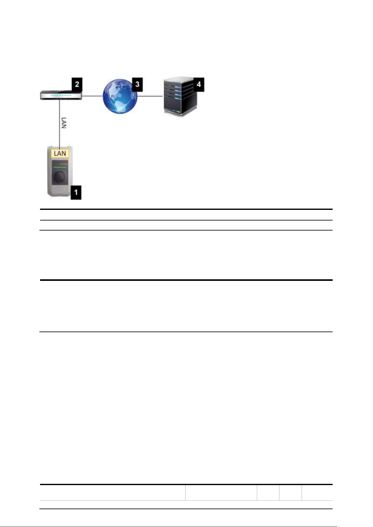
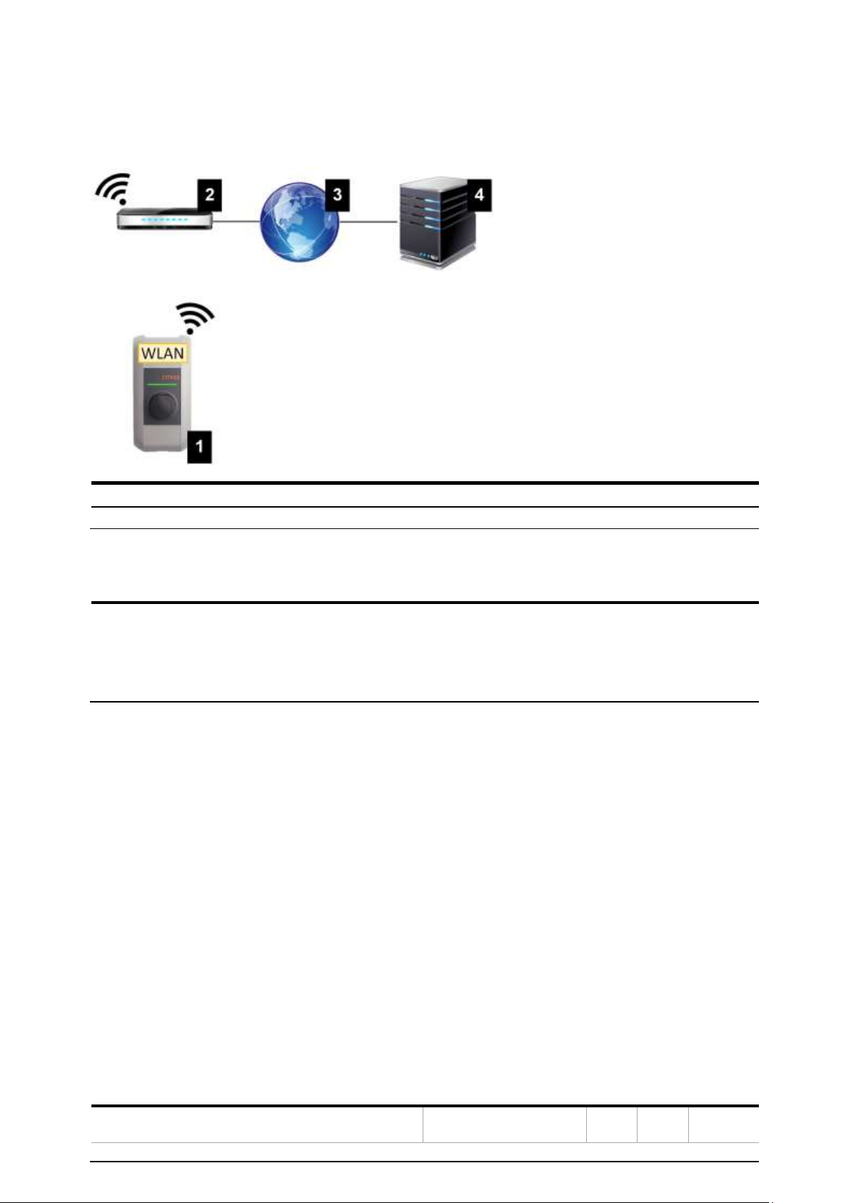
2.1. Network interfaces .............................................................................................................................................. 8
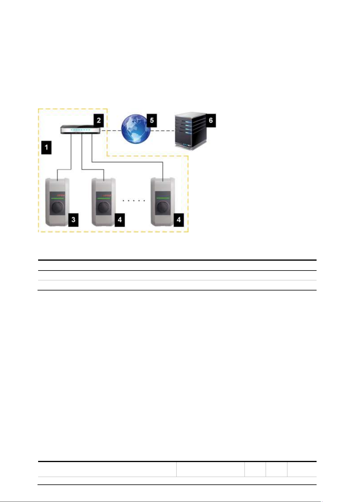
2.2. Design of a local charging network (master/slave) ....................................................................................12
3. Configuration ................................................................................................................................................15
3.1. Connection panel ................................................................................................................................................15
3.2. DIP switch settings.............................................................................................................................................15
3.3. Configuration via web interface ...................................................................................................................... 17
3.4. Enabling the DHCP server.................................................................................................................................23
3.5. Configuration in series via USB stick .............................................................................................................23
4. Functions .......................................................................................................................................................26
4.1. Load management in the local charging network...................................................................................... 26
4.2. RFID authorization..............................................................................................................................................27
4.3. OCPP backend .................................................................................................................................................... 30
4.4. UDP interface.......................................................................................................................................................31
4.5. Integration of external meters ........................................................................................................................31
5. Maintenance ..................................................................................................................................................35
5.1. Diagnosis and troubleshooting ...................................................................................................................... 35
5.2. Software update ................................................................................................................................................ 35

CHA RG ING STATIO N
STATUS
Released
DOCUMENT ID.
TBA
REV.
A
LANG.
EN
PAGE
3/37
© Copyright 2019 ABB. All rights reserved.
1. Introduction
This document refers to the following devices:
EVLunic Pro M with software version 1.8 or a later version of the software
The device variant can be determined by the product designation on the type plate. The software
version can be read out via the web interface. For more information, see the "operating instructions".
The pictured devices used in this manual are visual examples. The figures and explanations contained in
this manual refer to a typical device design. The devices used by you may differ in their appearance.

CHA RG ING STATIO N
STATUS
Released
DOCUMENT ID.
TBA
REV.
A
LANG.
EN
PAGE
4/37
© Copyright 2019 ABB. All rights reserved.
1.1. Representation of safety instructions
At various points in this manual, you will see notes and precautionary warnings
regarding possible hazards. The symbols used have the following meaning:
DANGER!
indicates an imminently hazardous situation, which will result in death or
serious bodily injury if the corresponding precautions are not taken.
WARNING!
indicates a potentially hazardous situation, which can result in death or
serious bodily injury if the corresponding precautions are not taken.
CAUTION!
indicates a potentially hazardous situation, which can result in death or
serious bodily injury if the corresponding precautions are not taken.
CAUTION!
means that damage to property can occur if the corresponding safety
measures are not taken.
ESD
This symbol reminds you of the possible consequences of touching
electrostatically sensitive components.
Information
Identifies practical tips and useful information. No information that warns
about potentially dangerous or harmful functions is contained.

CHA RG ING STATIO N
STATUS
Released
DOCUMENT ID.
TBA
REV.
A
LANG.
EN
PAGE
5/37
© Copyright 2019 ABB. All rights reserved.
1.2. Purpose of the document
This document describes the configuration of the advanced features of EVLunic Pro M after it has been
installed. This includes, among other things, the description of the settings in the web interface.
This document is an extension to the supplied manuals of EVLunic Pro M.
You must comply with all instructions and safety instructions in the supplied manuals!
1.3. Requirements
This document contains information for persons with the following requirements:
Target group
Required knowledge and abilities
Electrician
Person who, due to his or her special training, expertise and experience
as well as knowledge of current standards, is able to assess the work
performed and the possible hazards.
Knowledge of:
•current valid safety information,
•the mode of operation of the charging station,
•the displays and operating elements of the charging station,
•basics of network technology,
•basics of IT,
•diagnostic options,
•systematic fault analysis and rectification,
•the setting options on the charging station.
1.4. Guarantee
Only the maintenance work expressly permitted by ABB may be performed. Any other manipulations to
the device will also result in loss of warranty.
WARNING!
Danger due to electric shock and fire hazard!
After opening the front part, product safety can no longer be guaranteed.
Only the covers described in the instructions may be opened. If one of the covers is sealed by a lead seal,
it is not permitted to be opened by unauthorized persons. If the lead seal is broken, the device loses its
specific suitability and may no longer be put into operation due to the resulting incorrect marking.

CHA RG ING STATIO N
STATUS
Released
DOCUMENT ID.
TBA
REV.
A
LANG.
EN
PAGE
6/37
© Copyright 2019 ABB. All rights reserved.
—
Fig. 1-1: Screws on front part
The front part 1 may not be opened. Opening the front part (4 Torx screws) will break the warranty seal
and void the warranty. For a warranty claim, there is a duty of proof of the customer that the defect –
which led to the defect of the device – already existed at the time of delivery. If the warranty seal is
broken, this proof can no longer be provided, whereby the warranty claim expires.
A device with broken warranty seals or removed lead seals may no longer be put into operation. The
necessary steps for replacement or repair of the charging station by the specialist dealer or service
partner must be initiated.
1.5. Notes on this document
The manual is part of the product. It is to be retained over the entire life cycle of the product and should
be forwarded to any subsequent owners or users of the product.
The instructions contained in this manual must be followed precisely. Failure to do so could result in the
creation of potential sources of danger or the disabling of safety devices. Apart from the safety
instructions given in this manual, the safety precautions and accident prevention measures appropriate
to the situation in question must also be observed.
1.5.1. Contents of the document
•Configuration of the advanced features of EVLunic Pro M
1.5.2. Not contained in this document
•Commissioning and deinstallation of the charging station
•Operating behavior of the charging station
•Operation of the charging station

CHA RG ING STATIO N
STATUS
Released
DOCUMENT ID.
TBA
REV.
A
LANG.
EN
PAGE
7/37
© Copyright 2019 ABB. All rights reserved.
1.6. Further documentation
Manuals and additional information are available on the ABB website:
new.abb.com/ev-charging
Designation
Target group
Operating instructions
•End customer
•Electrician
Installation manual
•Electrician
UDP Programmers Guide
•Programmer
FAQ
•End customer
•Electrician
•Service technician

CHA RG ING STATIO N
STATUS
Released
DOCUMENT ID.
TBA
REV.
A
LANG.
EN
PAGE
8/37
© Copyright 2019 ABB. All rights reserved.
2. System overview
With EVLunic Pro M, several charging stations can be interconnected in the form of a master/slave
network. This makes charging with an intelligent load management possible. In addition, a connection
to a higher-level OCPP backend can take place. The charging station is equipped with different network
interfaces for these functions.
—
Fig. 2-2: Example network setup
1 Local charging network
2 Router/Switch
3 Master charging station (Pro M)
4 Slave charging station (Pro S)
5 Higher-level network/Internet
6 OCPP backend
Only EVLunic Pro M can be operated as master charging stations; only EVLunic Pro S can be operated as
slave charging stations.
The following chapters describe which network interfaces EVLunic Pro M (master charging station)
provides and how to set up a master/slave network.
2.1. Network interfaces
EVLunic Pro M provides the following network interfaces (e.g. for connection to an OCPP backend, ...):
•LAN
•WLAN (optional)
•WLAN access point (optional)
•GSM (optional)
Slave charging stations can only be connected via LAN to EVLunic Pro M (master charging station).

CHA RG ING STATIO N
STATUS
Released
DOCUMENT ID.
TBA
REV.
A
LANG.
EN
PAGE
9/37
© Copyright 2019 ABB. All rights reserved.
2.1.1. LAN
EVLunic Pro M can be connected to a router via the integrated LAN interface. The router provides a
connection to an OCPP backend over the Internet.
1 EVLunic Pro M
2 Router
3 Internet
4 OCPP backend
Connection: Ethernet1-Anschluss (LSA+®)
Via the LAN interface, EVLunic Pro M can also be connected to other charging stations, whereby a
charging network can be realized.
Information
The Ethernet2 connection X3 (RJ45) is for diagnose purposes (debugging) only
and may not be used to connect to a network.
The Ethernet1 connection X4 (LSA+®) and the Ethernet2 connection X3 (RJ45)
are connected in parallel on the PCB and cannot be used at the same time! The
connection that is not used must be unplugged from the charging station.

CHA RG ING STATIO N
STATUS
Released
DOCUMENT ID.
TBA
REV.
A
LANG.
EN
PAGE
10/37
© Copyright 2019 ABB. All rights reserved.
2.1.2. WLAN (optional)
EVLunic Pro M can be connected to a router via the integrated WLAN interface. If the router is connected
to the Internet, a connection to an OCPP backend can be made.
1 EVLunic Pro M
2 Router
3 Internet
4 OCPP backend
The technical data of the WLAN module can be found in the "Installation Manual".
Information
Only a charging station that is operated as a single charging station can be connected to the router via
WLAN. A charging station that is part of a charging network (master/slave network) must always be
connected to the router via LAN.

CHA RG ING STATIO N
STATUS
Released
DOCUMENT ID.
TBA
REV.
A
LANG.
EN
PAGE
11/37
© Copyright 2019 ABB. All rights reserved.
2.1.3. WLAN Access Point (Hotspot) (optional)
EVLunic Pro M can be connected to a mobile device via the integrated WLAN access point. With the
mobile device, the web interface can be easily accessed and the configuration of the charging station
can be performed.
1 EVLunic Pro M
The access data and the IP address of the WLAN access point are listed on the configuration label. The
configuration label is in a pouch which is enclosed with the mounting material.
The following steps are necessary to perform the configuration via a mobile device:
1. Connect a mobile device to the WLAN access point.
2. Access the IP address of the WLAN access point in a web browser on the mobile device.
3. Perform configuration via the web interface, see 3.3 Configuration via web interface.
2.1.4. GSM (optional)
Certain device variants have a GSM module. EVLunic Pro M with GSM can connect to an OCPP backend
over the cellular network. The mobile communications provider may charge additional fees (depending
on the tariff) for running data transmissions.
1 EVLunic Pro M
2 OCPP backend
For the connection to an external OCPP backend via GSM, a SIM card must be installed during
commissioning. In addition, GSM must be activated as connection to the OCPP backend and the
access data of the mobile service provider must be set in the configuration (web interface).

CHA RG ING STATIO N
STATUS
Released
DOCUMENT ID.
TBA
REV.
A
LANG.
EN
PAGE
12/37
© Copyright 2019 ABB. All rights reserved.
The commissioning of the GSM module is described in the "Installation Manual". The technical data of
the GSM interface and the SIM card can also be found in the "Installation Manual".
2.2. Design of a local charging network (master/slave)
A local charging network includes one EVLunic Pro M as master and up to 15 EVLunic Pro S as slaves.
Depending on the number of slave charging stations, the design of a local charging network is
implemented differently:
•1 slave charging station: Direct connection
The slave charging station is connected directly to the master charging station.
•Multiple slave charging stations: Connection via router or switch
The slave charging stations are connected to the master charging station via a router or switch.
To enable communication between master and slave charging stations, the charging stations must be
configured in the web interface, see 3 Configuration.
2.2.1. Displays and signals
The display on the front of the charging station provides information about which communication
connection is established.
Display
Description
blue | blue | blue | blue
Communication is possible throughout the network.
The master charging station and the OCPP backend are reachable.
blue | blue | blue | –
Communication between master and slave charging stations is possible.
The OCPP backend is not reachable or missing.
– | blue | blue | –
Communication between master and slave charging stations is not
possible.
The OCPP backend is not reachable.

CHA RG ING STATIO N
STATUS
Released
DOCUMENT ID.
TBA
REV.
A
LANG.
EN
PAGE
13/37
© Copyright 2019 ABB. All rights reserved.
2.2.2. Direct connection of master and slave
A single slave charging station can be connected directly to the master charging station via LAN.
—
Fig. 2-3: Direct connection of master and slave
1 EVLunic Pro M (master)
2 EVLunic Pro S (slave)
In this case, the master charging station must be configured as a DHCP server. The IP address is then
assigned to the slave charging station by the master charging station.
2.2.3. Connection via router or switch
If there are multiple slave charging stations, these must be connected to the master charging station via
a router or switch. The connection of the charging station to the router/switch is made via LAN
—
Fig. 2-4: Connection via router or switch
1 Router/Switch
2 EVLunic Pro M (master)
3 EVLunic Pro S (slave)

CHA RG ING STATIO N
STATUS
Released
DOCUMENT ID.
TBA
REV.
A
LANG.
EN
PAGE
14/37
© Copyright 2019 ABB. All rights reserved.
Using a router
In a network connection using a router, the router automatically provides the functionality of a DHCP
server in most cases.
Information
If the IP addresses are assigned externally (for example, by routers with
activated DHCP server), the IP addresses must not be in the following range:
192.168.25.xxx
Using a switch
For a network connection using a switch, the master charging station must be configured as a DHCP
server. The IP addresses are then assigned by the master charging station.
2.2.4. Ports for communication in the charging network
For the correct communication in the charging network, the ports below must be enabled network-
internally
Information
If necessary, contact your network administrator to enable the ports.
Port
Protocol
Definition
Description
49153
TCP
Within the network
Socket of the charging station
15118
TCP
Within the network
Link connection between the charg
ing stations (SDP)
15118
UDP
Within the network
Link connection between the charg-
ing stations (SDP)
68
TCP
Within the network
Transfer of the software update
(Bootps)
68
UDP
Within the network
Transfer of the software update
(Bootps)
67
TCP
Within the network
Transfer of the software update
(Bootps)
67
UDP
Within the network
Transfer of the software update
(Bootps)

CHA RG ING STATIO N
STATUS
Released
DOCUMENT ID.
TBA
REV.
A
LANG.
EN
PAGE
15/37
© Copyright 2019 ABB. All rights reserved.
3. Configuration
This chapter describes the necessary configuration for the correct operation of the charging stations.
The following steps are necessary for this:
•Set the DIP switch on the charging station
•Configuration (via the web interface or via USB stick)
Depending on the network configuration, activation of the DHCP server on the master charging station
may be necessary.
3.1. Connection panel
In the connection panel of the charging station are important interfaces and controls for the
configuration of the charging station. To access, the housing cover and the connection panel cover must
be removed. The description of removing the covers and the connection panel can be found in the
"Installation Manual".
3.2. DIP switch settings
This DIP switch setting must be made for each master and slave charging station to enable charging
station communication.
Caution!
Possible damage to the DIP switches!
The DIP switches are rocker switches and not slider switches. The DIP switches
must be pressed and must never be slid.
ON/OFF position of the rocker switches
The illustration shows the position of the rocker switches for the setting ON and OFF

CHA RG ING STATIO N
STATUS
Released
DOCUMENT ID.
TBA
REV.
A
LANG.
EN
PAGE
16/37
© Copyright 2019 ABB. All rights reserved.
The DIP switches are located under the connection panel cover. The following figure shows only the
affected DIP switches, others are not shown. The following setting must be made on the DIP switch
DSW2:
Activation of communication - DSW2.5
Function
Figure
Activation of communication
Information
Changes to the DIP switch settings only become effective after a restart of the
charging station!
To restart, press the "Service button" until the first beep (approx. 1 second) or
switch off the charging station for a short time via the line circuit breaker

CHA RG ING STATIO N
STATUS
Released
DOCUMENT ID.
TBA
REV.
A
LANG.
EN
PAGE
17/37
© Copyright 2019 ABB. All rights reserved.
3.3. Configuration via web interface
The necessary settings (main menu "Configuration") for the communication of the charging station are
configured in the web interface. The configuration for the entire charging network is done via the master
charging station.
A network connection is required to access the web interface of the master charging station. The
network connection can be made via LAN, WLAN, WLAN access point or GSM (e.g. with PC or mobile
device).
The web interface of the master charging station can be accessed by entering the IP address of the
master charging station in a web browser.
The IP address of the master charging station is determined differently depending on the connection
type.
WLAN access point
The IP address of the WLAN access point is printed on the
configuration label.
Router with integrated DHCP
server
The charging station automatically receives an IP address via the
DHCP server of the router. The IP address is displayed on the
charging station display when the charging station is (re)started.
The IP address can also be determined via the router.
Master charging station with
local DHCP server
The local DHCP server has been activated for the master charging
station, which automatically gives the master charging station
the following IP address: 192.168.42.1
The DHCP server of the charging station is deactivated in the
delivery state and can be activated via the configuration in the
web interface.
A login is required to use the web interface.
The login data for the first login in the web interface is printed on the configuration label. The
configuration label is in a pouch which is enclosed with the mounting material. For security reasons,
change the password after the initial login.
Fig. 3-5: Configuration label

CHA RG ING STATIO N
STATUS
Released
DOCUMENT ID.
TBA
REV.
A
LANG.
EN
PAGE
18/37
© Copyright 2019 ABB. All rights reserved.
After successful login, the start page of the web interface opens.
Fig. 3-6: Web interface start page
1 Main menu
2 User menu
The following chapters provide an overview of the possibilities of the web interface. A detailed
description of the individual configuration options can be found directly next to the respective
configuration entry.

CHA RG ING STATIO N
STATUS
Released
DOCUMENT ID.
TBA
REV.
A
LANG.
EN
PAGE
19/37
© Copyright 2019 ABB. All rights reserved.
3.3.1. Main menu
The main menu is divided into the following areas:
•Status
•RFID cards
•System
•Configuratio
Status
This page is divided into the following sections:
Overview
Basic information about all charging stations in the charging network (such as: serial number, IP
address, operating state ...) is displayed here. Next to each listed charging station there is a "Restart"
button to restart the charging station.
By clicking on the respective IP address, a new browser window displays charge information, such as
total power, charge session power, power, voltage, current, state, and event log. The scope of the
displayed information is variant-dependent.
Network Connection
Information about the network interfaces (LAN, GSM, WLAN and WLAN access point) of the master
charging station is displayed here.
Backend
Information about the OCPP backend (such as connection state and address) is displayed here.
RFID cards
This page provides an overview of all stored RFID cards including their authorizations. RFID cards can be
taught-in, edited and deleted. RFID cards can also be exported and imported as *.csv file.
System
The area offers the following options:
•Software-Update
•GSM Info
•WLAN Access Point Info
•Logging
•DSW settings
•Restart System
Software-Update
The currently installed software versions are displayed. A software update can also be performed here.
GSM Info
Information about the GSM connection is displayed and the connection to the set GSM network can be
tested.

CHA RG ING STATIO N
STATUS
Released
DOCUMENT ID.
TBA
REV.
A
LANG.
EN
PAGE
20/37
© Copyright 2019 ABB. All rights reserved.
WLAN Access Point Info
The state of the WLAN access point (hotspot) is displayed.
Logging
Different event logs of the master charging station are displayed.
DSW settings
The DIP switch settings of each charging station in the charging network can be displayed here.
Restart System
The master charging station can be restarted using this button.
Configuration
The configuration of the charging station is carried out in this area.
Information
The DIP switch settings are independent of the web interface configuration and cannot be overwritten
by software.
The area offers the following options:
•Operating Mode
•Device
•Phase Assignment
•Charging Parameters
•Network Connection
•Certificates
•WLAN / WiFi Access Point
•Proxy
•OCPP
•External TCP Meter
•Display Text
Information
The settings made are only applied after the "Apply" button has been pressed.
Operating Mode
Here you can determine whether the charging station is operated as a single charging station or as a
master charging station in a charging network.
The number of slaves must be entered for a charging network. In addition, all attached slave charging
stations must be entered with their respective serial numbers. Otherwise, the slave charging station will
not be recognized by the master charging station in the network. The serial number is printed on the
rating plate of the slave charging station.
Table of contents
Other ABB Batteries Charger manuals

ABB
ABB HT607866 User manual

ABB
ABB HT842379 User manual

ABB
ABB Terra 94 North America Specification sheet

ABB
ABB HT580272 User manual

ABB
ABB A101-H Series User manual

ABB
ABB HT564102 User manual

ABB
ABB HT572043 User manual

ABB
ABB HT594058 User manual

ABB
ABB TPS44-F Series User manual

ABB
ABB HT562804 User manual