Adel System CB245ARJ User manual
A
AD
DE
EL
L
s
sy
ys
st
te
em
m
Instruction Manual
ADEL system srl Via F. Bacone 13/E, 42029 Masone RE (Italy) – Tel. ++39-0522-345518
Fax. ++39-0522-345551 – Internet: www.adelsystem.com
CB245A_R0 120W Eng.doc
CB245ARJ
Intelligent Battery Charger
Thank you for having chosen one of our products for your work. We are certain that it will give the utmost satisfaction and be a notable
help on the job.
General Description:
Application
CBI battery charger is a range of microprocessor-power supplies witch correctly charge sealed lead-acid batteries at all time
maximizing performance and life span.
Charge the battery in multi-stage principle, Fast and Trickle and automatically the device, check the battery efficiency in a lifetime to
prevent any risk of damage to the battery and allow leaving the charger permanently connected. Before begin the operations of
installation consult the manual.
Mains Characteristic
•Nominal Input Voltage: 115 - 230 Vac
•OUTPUT 1: for connection to Battery
•OUTPUT 2: not present
•Fast and trickle battery charge In according to DIN 41773
•Signaling: replace battery, low battery, mains or buffering
•Overload and short circuit protections
•Safety isolation in according with EN 60950
•Degree of protection IP20
•Rail DIN mounting
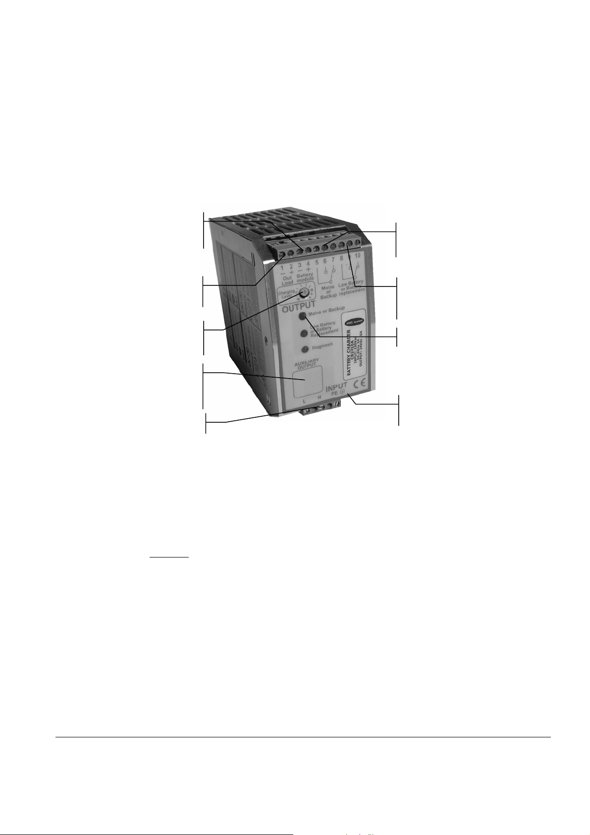
Vac Input
Mains or
Backup
OUTPUT N°2
Not present
Charging Level
OUTPUT N°1
Battery module
Low Battery or
Battery replacement
Battery Type
Configuration Jumper
Monitor Led
Auxiliary
Output
(CBXXX/ARJ)
________________________________________________________Battery Charger
All specification are subject to change without notice
INSTRUCTION MANUAL 2
CB245A_R0 120W Eng.doc
Rail mounting:
Other modules must have a minimum vertical distance of 10 cm to this power supply in order to guarantee sufficient auto convection.
Use and Connections
Caution: Switch off the system before connecting the module. Never work on the machine when it is live.
Charging Level Current: With trimmer from 20% to 100% of In. Select the max. battery charge current estimated from 10 to 25% of
the nominal Battery capacity.
Battery module (Output 1) 3-4 Pin: Battery Input and diagnosi led: very fast blinking= recovery charging ( when the battery is too
low) , fast blinking=fast charge, slow blinking=trickle charge
Mains or Backup: Mains with led off and closed contact (5-6), Backup with led on and closed contact (5-7).
Low Battery or Battery replacement: Normal condition with battery OK, led Off and closed contact (8-9), Low Battery with battery
NOK, led ON and closed contact (8-10), Battery replacement alarm with Power ON , led ON and closed contact (8-10); (see
diagnostic Led ).
Life Test Battery : In trickle charge condition check every 4 hours, internal impedance (5 blinking Diagnosis Led)
Diagnosis Led
Very fast blinking= recovery charging ( when the battery is too low, Under 20 Vdc)
Fast blinking= fast charge.
Slow blinking= trickle charge (floating charge)
1 blinking= Reverse polarity battery; Bad input voltage battery.
2 blinking= Battery not connected.
3 blinking= Short circuit battery element.
4 blinking= Over Load.
5 blinking= Bad battery.( Internal impedance Bad or Bad battery wire connection)
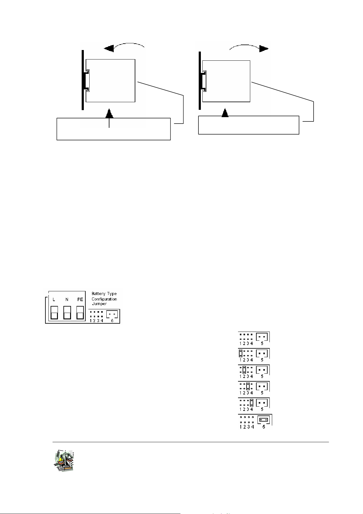
Battery Type Configurations
Position jumper Setting:
•Open Lead (Charge): Trickle =2.23 Fast=2.40/cell
•Sealed Lead (Charge): Trickle =2.25 Fast=2.40/cell
•Sealed Lead (Charge): Trickle =2.27 Fast=2.40/cell
•Gel Battery (Charge): Trickle =2.30 Fast=2.40/cell
•Life Test Battery
•No jumper no Fast Charge (pos. 5)
Disassembling:
Push the module upwards and pull.
Assembly: Place the module with the mounting rail
guide at the lower edge, and snap in whit an
upward movement.
Caution: Switch off the system before Setting the jumper.
Only jumper in position 5 Refresh ON/OFF state whit Power.

________________________________________________________Battery Charger
All specification are subject to change without notice
INSTRUCTION MANUAL 3
CB245A_R0 120W Eng.doc
Compensation Recharges in temperature (Only version XXX/ARJ-S2)
Connecting to RJ45 (AUXILIARY OUTPUT) cable RJTEMP (supplied separately), the CBI is will vary the tension of battery charging in
function of the temperature:
•Fast Charge: -5 mV/°C
•Trickle Charge: -3 mV/°C
If the sensor is not connected or if the sensor is defective, the led Low Batt is on and the led Diagnosis continues to show the status of
the battery: trickle charge, fast charge or recovery charge.
N.B.: the sensor place on cable RJTEMP must be applied on the battery.
Cable connection
The following cable cross-sections may be used:
At the Input: 0.2÷2.5 mm2 rigid / flexible
At the Output: 0.2÷2.5 mm2 rigid / flexible
Strip the connection ends: 7mm
Input: The input connection is made by the screw connections L, N, PE .
Protection
On the primary side: the device is equipped whit a internally fuse T 4 A/250Vac. If the internal fuse is activated, it is most probable
that there is a fault in the device. If happen, the device must be checked in the factory.
On the secondary side Battery: The device is electrically protected against short circuits and overload.
Inversion polarity: the module is protected against inversion of battery polarity.
Over current and output short circuit: the unit limits the output current at max. 12 A in normal rating.
Deep discharge : not possible. The unit disconnects the battery when a minimum voltage level is reached.
Battery Test: Automatic. Every 20 sec. check polarity and battery. Every 4 hours in trickle charge, make the test of the battery
efficiency. The fault is signalized with relay commutation and diagnosis led blinking.
Characteristic Curves
Short circuit and overload
The output of the device is electrically protected against overload and short circuit.
At nominal voltage the device can supply 1.1 the nominal Current without
switching off. In the case of higher overload, the operating point traces the curve
illustrated in figure. As the overload increases, the output voltage is reduced until
zero.
Thermal behavior
The device supplies the nominal output current at ambient temperature of up
50°C. For ambient temperature of over 50°C, the output current must be reduced
by 1% per °C increase in temperature. Max 70°C.
Standards and Certification
Electrical safety
The device must be installed in according with EN60950. The device must have a suitable isolating facility outside the power supply
unit, via which can be switched to idle.
General Standard
Immunity in according with EN50082-2, level 4, class B
Radio interference suppression in according with EN 55011 class A (industrial areas)

________________________________________________________Battery Charger
All specification are subject to change without notice
INSTRUCTION MANUAL 4
CB245A_R0 120W Eng.doc
Features
Input Data
Nominal Input Voltage (2 x Vac) 110- 230 Vac
Input voltage range 93 ÷ 264 Vac
Inrush Corrent (Vn – In) ≤14 ≤5 msec.
Frequency 47 ÷ 63 Hz
Input Current (Nominal input Voltage) 1,5 - 0.9 A
Internal Fuse F 4 A
External Fuse (recommended) Fast 6 A
Output Data
Output Voltage Battery Bulk Charge / Nominal Current Max 28.8 Vdc / 5 A
Output Voltage Battery Trickle Charge / Nominal Current Max 27.0 Vdc / 5 A
Adjustment range of charge (In adj) 20 ÷ 100% In
Type of charging characteristic U/I
End of charging voltage (Bulk charge) Max 28.8 Vdc
End of charging current (Bulk charge) 0.3 A
Type battery up to 50 Ah
Start up with capacitv load ≤30.000 μF
Switching on after applying mains voltage 2,5 sec. max
Current max. 1.1 x IN ±5%
Residual Ripple ≤60 mVpp
Minimum Load No
Efficiency ≥81 %
Short-circuit protection Yes
Over Load protection Yes
Over Voltage Output protection Yes
Reverse battery protection Yes
Climatic Data
Ambient Temperature (operation) -10 ÷ +50 °C
Ambient Temperature (Storage) -25÷ + 85 °C
Humidity; no moisture condensation 95 % a 25°C
General Data
Isolation Voltage (Input/ output) 3000 Vac
Input ground insulation 1605 Vac
Electrcal safety EN 60950
Degree of protection IP 20
Protection class I with PE connected
Dimension (w-h-d) 65x115x135
Weight 0.6 Kg approx
In according to EMC 89/336/EEC and Low voltage 93/68/EEC
Other Adel System Batteries Charger manuals


Popular Batteries Charger manuals by other brands


Manson Engineering Industrial
Manson Engineering Industrial CBC-9140 Operation manual

Battery Tender
Battery Tender Junior User instructions

HIKOKI
HIKOKI UC 18YGH Handling instructions

Wallbox
Wallbox Pulsar Plus installation guide

Anker
Anker PowerWave II A2529 instructions

AMX
AMX Battery Base and Accessories NXA-BASE/B installation guide


