ADGT EDM106 User manual
EDM Serial-to-Ethernet
Converters
User Guide

EDM Serial-to-Ethernet Converters
User Guide ver. 2.0 | 2021-09-01
Phone: +420 538 890 720 2E-mail: [email protected]
EDM Serial-to-Ethernet Converters
User Guide (Ver. 2.0 | 2021-09-01)
The user guide is intended for persons who install, configure and maintain industrial Ethernet converters –
RS-232/RS-485/RS-422 EDM106 Series (hereinafter referred to as converters). The manual contains information
about the purpose, design, technical parameters and operating principles of the converters.
ADGT systems s.r.o. reserves the right, without any prior notice, to make changes to the User Guide, related to
the improvements of hardware and software, as well as to eliminate typos and inaccuracies.
Copyright © ADGT systems s.r.o., Prague, 2021.
All rights reserved.
This document is the property of ADGT systems s.r.o.
Printing allowed for private use only.

EDM Serial-to-Ethernet Converters
User Guide ver. 2.0 | 2021-09-01
Phone: +420 538 890 720 3E-mail: [email protected]
Content
Chapter 1. Product Overview................................................................................................................... 4
Purpose........................................................................................................................................................................................4
Technical specifications .........................................................................................................................................................5
Product appearance ...............................................................................................................................................................6
Connector DB-9F of RS-232 interface .............................................................................................................................7
LED Indication...........................................................................................................................................................................7
Chapter 2. Operating the converter........................................................................................................ 9
Connection and installation.................................................................................................................................................9
Configuring EDM Converter..............................................................................................................................................10
Configuring Converter via Web Interface...........................................................................................................10
Configuring Converter via Console port (RS-232)..........................................................................................14
Reading Logs...........................................................................................................................................................................15
Reboot and factory reset ....................................................................................................................................................15
Firmware and Configuration Updates ...........................................................................................................................16
Appendix 1. List of commands for configuring converter via the console port .............................. 17
EDM Serial-to-Ethernet Converters
User Guide ver. 2.0 | 2021-09-01
Phone: +420 538 890 720 4E-mail: [email protected]
Chapter 1. Product Overview
Purpose
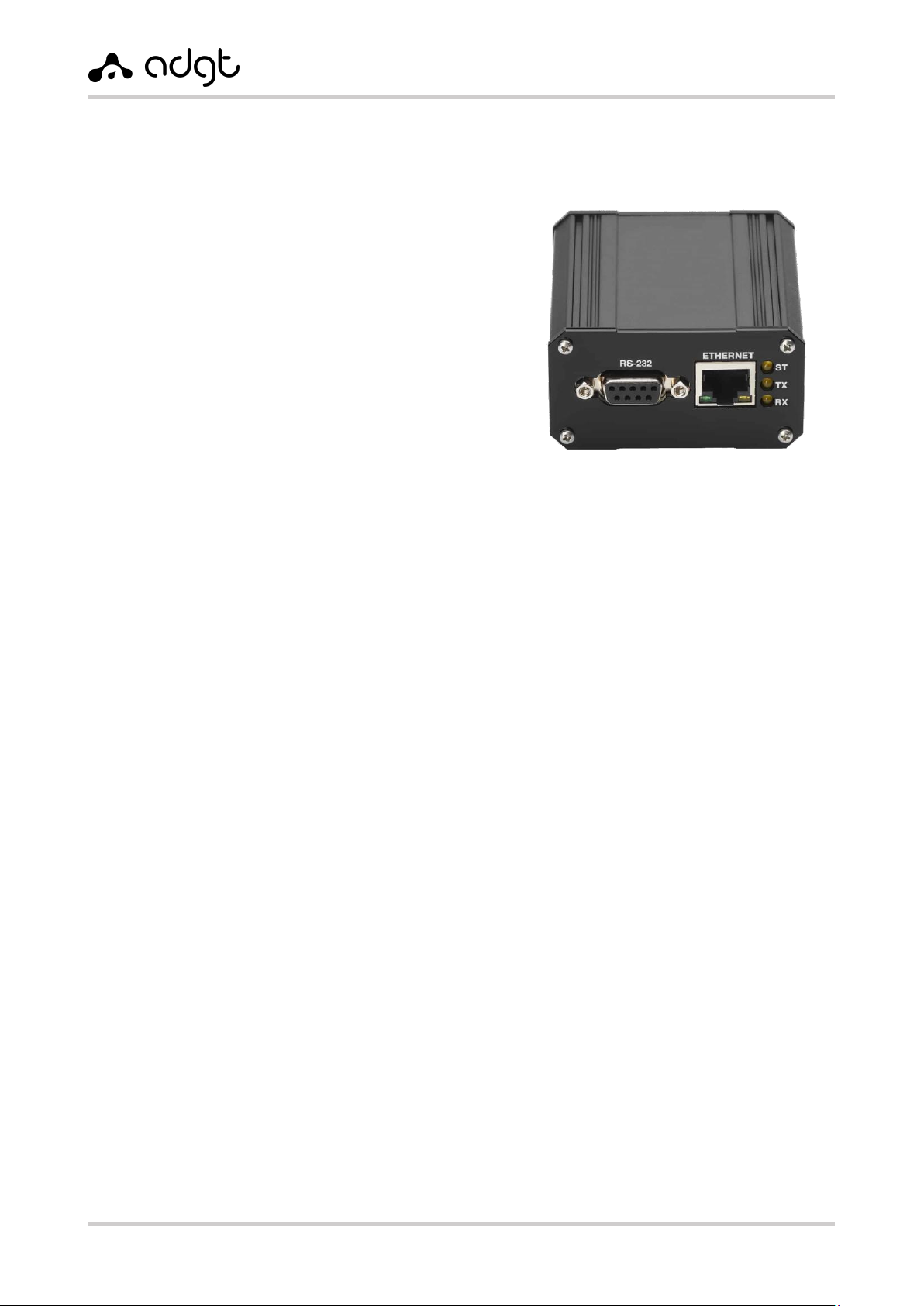
EDM106 – a series of bidirectional interface converters
for connecting the devices with RS 232/RS 485/RS-422
interfaces to Ethernet networks. Data received on the
Ethernet port over a TCP channel are transmitted to the
serial ports. Data received on the serial ports are
transmitted in TCP packets over Ethernet.
Converters are designed for data transmission in
systems for automation, dispatching and resource
accounting. The presence of independent interfaces RS-
232, RS-485 and RS-422 allows to use the converter to
connect a wide range of devices: meters, controllers,
sensors, actuators, PLCs, etc.
The series includes the following models:
EDM106 – converter with non-isolated RS-485 interfaces.
EDM106-G – converter with galvanically isolated interface RS-485 (package includes the
terminating resistor 120 Ohms and PVC tubing (Cambrick)).
Converter's features
•Independent interfaces RS-232, RS-485/RS-422 for connecting industrial devices. Connection of
up to 256 devices via RS 485/RS-422 interfaces.
•8.5V output for power supply of external devices.
•32-bit microcontroller, processing the network traffic efficiently.
•Operating modes TCP server and TCP client.
•Built-in DHCP-client and DNS-client.
•Watchdog reboot timer that protects the device from freezes and failures.
•Configuration of the converter through a simple and user-friendly web interface, as well as
through the console.
•Extended LED indication of: power supply, connectivity and activity of each port.
•The compact metal housing, allowing to install the converter into the telecommunication and
electrical cabinets.
•Supply voltage range: 10–30V DC.
•Wide operating temperature range: -40…+70C.
Scope of application
EDM106 converters are widely used in automated systems for monitoring and control of technological
objects and processes, allowing to poll the meters, to manage the loads, to perform remote
configuration and administration of industrial devices remotely.
Fig. 1. Converter EDM106.
EDM Serial-to-Ethernet Converters
User Guide ver. 2.0 | 2021-09-01
Phone: +420 538 890 720 5E-mail: [email protected]
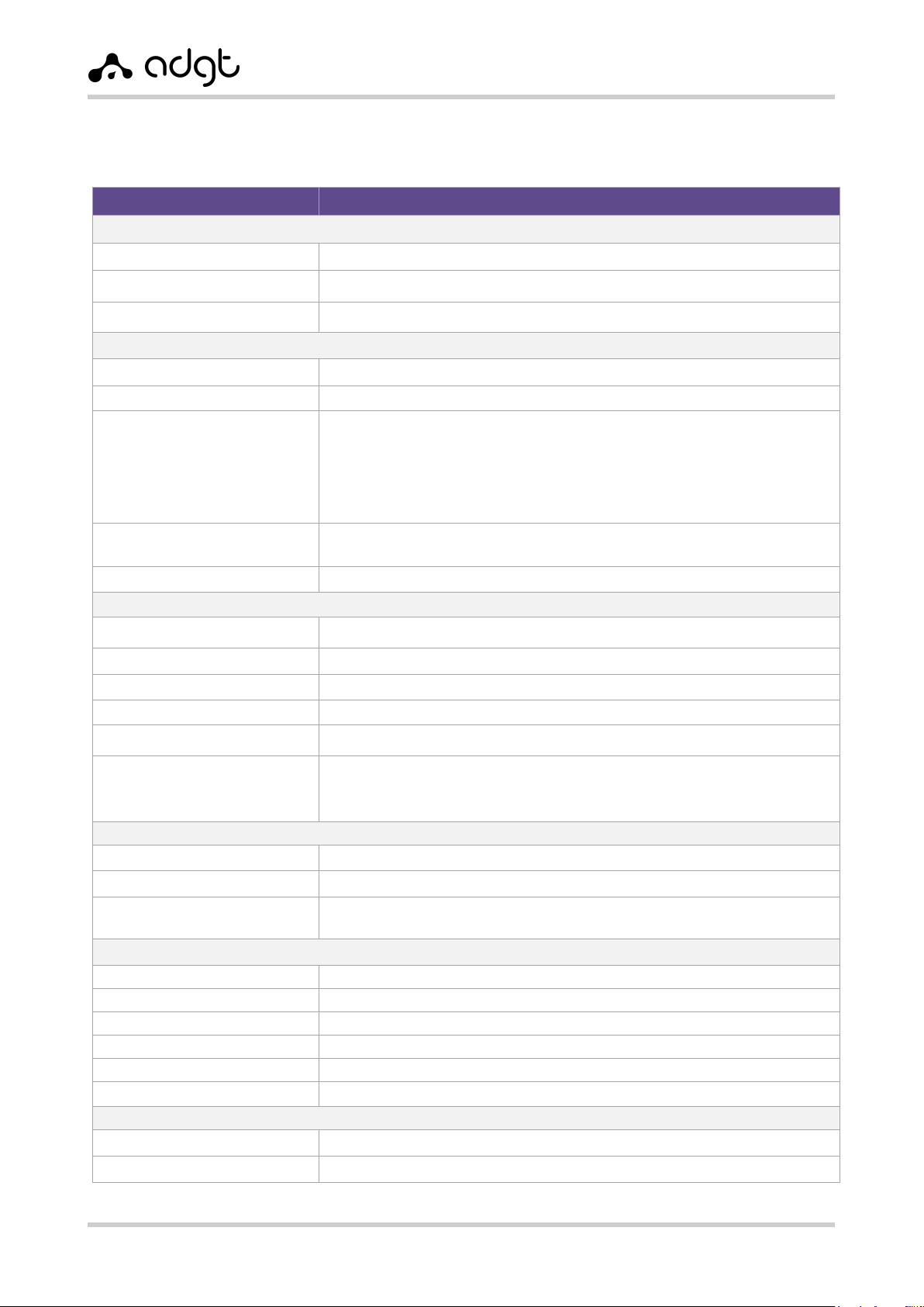
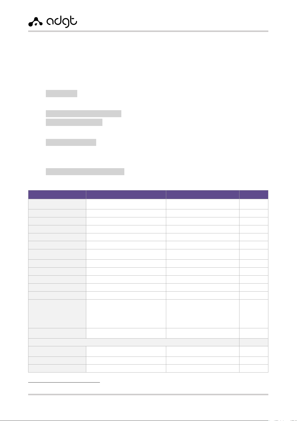
Technical specifications
Table 1. Converter EDM106. Technical specifications.
Parameter
Description
Microcontroller STM32F207VCT
Processor
ARM 32-bit CortexTM-M3 120 MHz
Flash-memory
256 Kb
RAM
128 Kb
Interfaces
Ethernet (x1)
RJ-45, 10/100 Base-TX. Transmition protocol: TCP/IP
RS-232 (x1)
DB-9F (COM-port)
RS-485 (x2)/RS-422 (x1)
Connector – terminal block (XP1, XP2: terminals A1, B1, A2, B2);
type of mating part - terminal block with screw connector (step – 3.81mm).
Max. communication range — up to 1000 m at 115200 bit/sec.
Load capability: up to 32 units of load or up to 256 devices with 1/8 of load
capability. Terminal resistor: pluggable (120 Ohm). Galvanical isolation: optional
(in the model EDM106-G)
Output 8.5V (x1)
8.5V output for power supply of external devices. Load current - up to 50 mA.
Connector – terminal block (XP2: terminal VO), step - 3,81 mm.
PWR (x1)
Connector – RJ-12, power supply voltage 10-30 V.
Parameters of serial interfaces
Port speed
600-115200 bit/sec
Number of data bits
7, 8
Parity check
none, odd, even
Stop bit length
1, 0.5, 1.5, 2
Flow control
enable / disable
Transmitted signals
RS-232: TxD, RxD, RTS, CTS
RS-485: Data A (+), Data B (-)
RS-422: Y+, Z-, A+, B-
Power supply
Power supply voltage
10...30 V DC
Power consumption
max. – 1.5 W
Connector
Connector – terminal block (XP2: terminals G(-) and VI(+)), step - 3,81 mm.
Connector – RJ-12
Mechanical parameters
Dimensions (L x W x H)
76 x 65 x 35 mm
Weight
122 g
Material of housing
aluminum alloy (IP30)
Installation options
DIN-rail, wall-mounted, desktop (rubber feet)
MTBF
100 000 hours
Average service life
10 years
Operating conditions
Operating temperature
-40...+70°C
Relative air humidity
no more than 95% at temperature +35°C
EDM Serial-to-Ethernet Converters
User Guide ver. 2.0 | 2021-09-01
Phone: +420 538 890 720 6E-mail: [email protected]
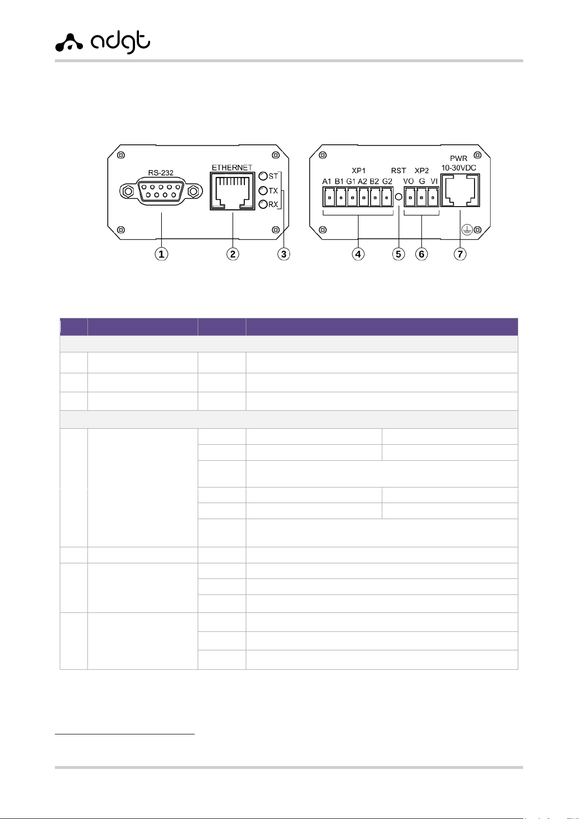
Product appearance
Design of the converter provides a metal housing with an IP30 protection class. Description of
connectors and buttons at the panels of the device case is presented on Fig. 2.
Table 2. EDM106. Description of contacts and connectors.
№
Connector
Contact
Description
Front panel view
1
RS-232
Interface RS-232, connector – DB9-F
2
ETHERNET
Ethernet 10/100Base-TX, connector – RJ45
3
ST, TX, RX
LED indicators ST, TX, RX
Back panel view
4
XP1
Connector -
breakaway
terminal block
A1
Signal “A+” RS-485 (1)
Output “Y+“ of RS-422 line
B1
Signal “B-” RS-485 (1)
Output “Z-“ of RS-422 line
T/T1
(G/G1)1
Lead of the pluggable terminal resistor 1
(connect with output B/B1 (“B-”) to plug-in)
A2
Signal “A+” RS-485 (2)
Output “A+“ of RS-422 line
B2
Signal “B-” RS-485 (2)
Output “B-“ of RS-422 line
T2 (G2)1
Lead of the pluggable terminal resistor 2
(connect with output B2 (“B-”) to plug-in)
5
RST
Reset / Switch to console mode button
6
XP2
Connector -
breakaway
terminal block
VO
Output 8.5B for power supply of external devices
G
Ground
VI
Low voltage power input 10-30 VDC
7
PWR
Connector - 6P6C
1
Low voltage power input 10-30 VDC
2,3,4,5
Not used
6
Ground
1
EDM106: T (T1, T2) – terminal resistor output.
EDM106-G: G (G1, G2) – isolated ground connector.
Fig. 2. Converter EDM106. Device appearance.
EDM Serial-to-Ethernet Converters
User Guide ver. 2.0 | 2021-09-01
Phone: +420 538 890 720 7E-mail: [email protected]
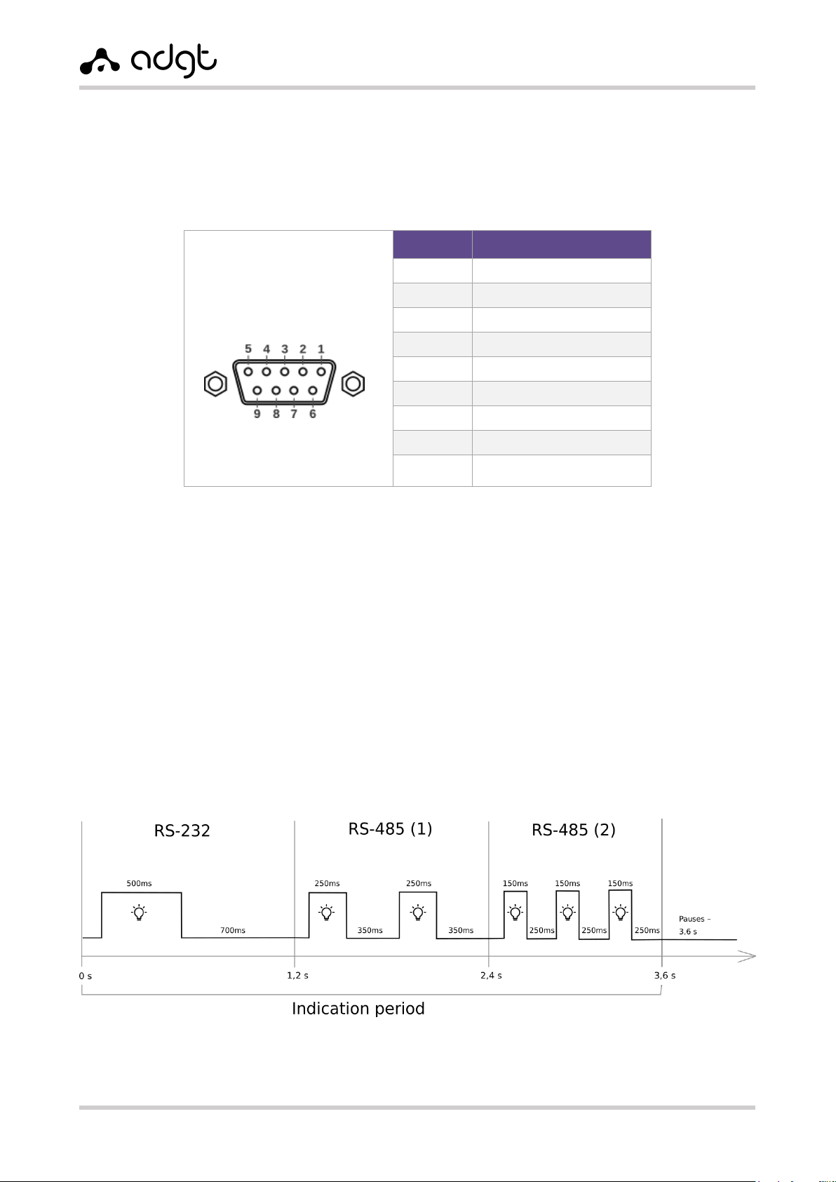
Connector DB-9F of RS-232 interface
Interface RS-232 of converters EDM106 has the standard 9-pin connector DB-9F. The pinout of the
connector is shown in Table 3.
Table 3. Pinout of DB9-F connector.
RS-232
(connector DB-9F)
Pin
Parameter
1
Output DCD
2
Output TX
3
Input RX
4
Input DTR
5
Ground
6
Output DSR
7
Input CTS
8
Output RTS
9
Output RING
LED Indication
The converters have three LED indicators:
RX – data reception,
TX – data transmission,
ST – indication of the connection of serial ports on TCP.
Algorithm of ST indicator operation:
Three timeslots of 1.2 s. for each interface (total - 3.6 s.):
Timeslot 1 –RS-232: one flash –500 ms, pause –700 ms.
Timeslot 2 –RS-485(1): two flashes –250 ms each, pauses –350 ms.
Timeslot 3 –RS-485(2): three flashes –150 ms each, pauses –250 ms.
Pause between the indication periods –3.6 s.
Fig. 3. Algorithm of ST indicator operation.

EDM Serial-to-Ethernet Converters
User Guide ver. 2.0 | 2021-09-01
Phone: +420 538 890 720 8E-mail: [email protected]
Table 4. Modes of indication.
ST
RX
TX
No power /
Connection standby mode
–
–
–
Power connection /
Resetting the device /
Factory settings reset
ST LED-indicator is on for 1 second, and then all LEDs flash
once alternately (from bottom to top and from top to
bottom)

EDM Serial-to-Ethernet Converters
User Guide ver. 2.0 | 2021-09-01
Phone: +420 538 890 720 9E-mail: [email protected]
Chapter 2. Operating the converter
Connection and installation
1. Connect external 12V power to terminals G and VI of the terminal block XP2 or to connector 6P6C
(PWR).
2. Connect the device to a local network (to a LAN hub or to a PC) using an Ethernet cable.
3. Connect the equipment with RS-232 and/or RS-485 interfaces to the corresponding connectors
of the converter.
Attention! For the models of converters with isolated RS-485 interfaces, fix the terminal
resistor in the isolated PVC tube and connect its contacts to terminals “A” and “B”.
4. To configure the converter through the web interface, launch a browser and enter into the address
line the default IP address of the device: 192.168.88.1.
5. An authorization window will appear in the browser window after the successful connection.
Default authorization data:
username –adgt
password –adgt.
The password can be changed in the General Settings section.
6. Configure the parameters of Ethernet and serial interfaces. By default, the serial ports are in the
Disabled state. Save the settings using the Setup button. List of configurable parameters and the
values of default parameter are available in section Configuring the converter through the web
interface.
Attention! When changing the used Ethernet standard in the network, to which the
converter is connected, for example, from 10BASE-T to 100BASE-T and vice versa, restart
the converter for the correct operation of the device.
7. Install the device. Depending on the type of mounting version, EDM106 converter can be placed
horizontally, on a flat surface, or mounted on a wall or on a DIN-rail (see sticker at the housing
for mounting options).
DIN-rail installation
For installation of converter onto a standard 35 mm DIN rail (H, Vmounts), the delivery pack includes
a set of plastic mounts (brackets). Mounting kit H includes 2 brackets and 4 self-tapping screws.
Mounting kit V includes 1 bracket and 2 self-tapping screws. To install the converter on a DIN rail,
attach the brackets with self-tapping screws to the holes on the device housing (2 self-tapping screws
for one bracket).
Installation of converter with R-type mount is performed onto a standard 35 mm DIN rail using a
metal plate with a clamp on the device housing.
Wall mounting
The converter with T-type mount is installed onto the wall with use of the metal mounting plate and
two screws. Two plastic dowels with screws are included into the delivery pack.
Attention! After three incorrect attempts to enter the username/password, the access
to the device will be blocked for 30 seconds.
EDM Serial-to-Ethernet Converters
User Guide ver. 2.0 | 2021-09-01
Configuring EDM Converter
The EDM106 converter can be configured in two ways: through the web interface and through the
console port (port RS-232).
Configuring Converter via Web Interface
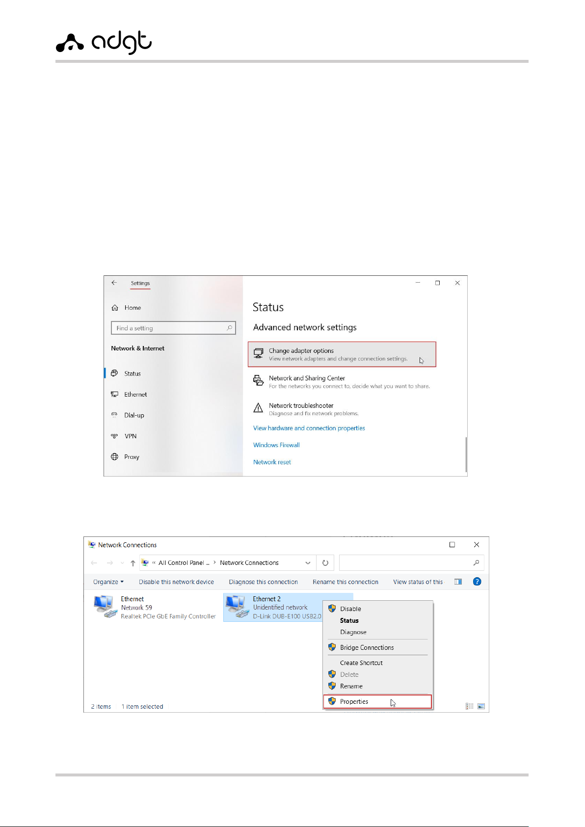
Setting up a local connection in Windows 10
After connecting converter to a PC or LAN hub, it is necessary to configure the local connection. Perform
the following steps to change the network parameters:
1. In Windows 10, click Start Settings Network and Internet.
2. Enter Change adapter options.
3. Right-click network adapter of the converter and then choose Properties.
Fig. 4. Menu "Change adapter options".
Fig. 5. Ethernet adapter properties.
EDM Serial-to-Ethernet Converters
User Guide ver. 2.0 | 2021-09-01
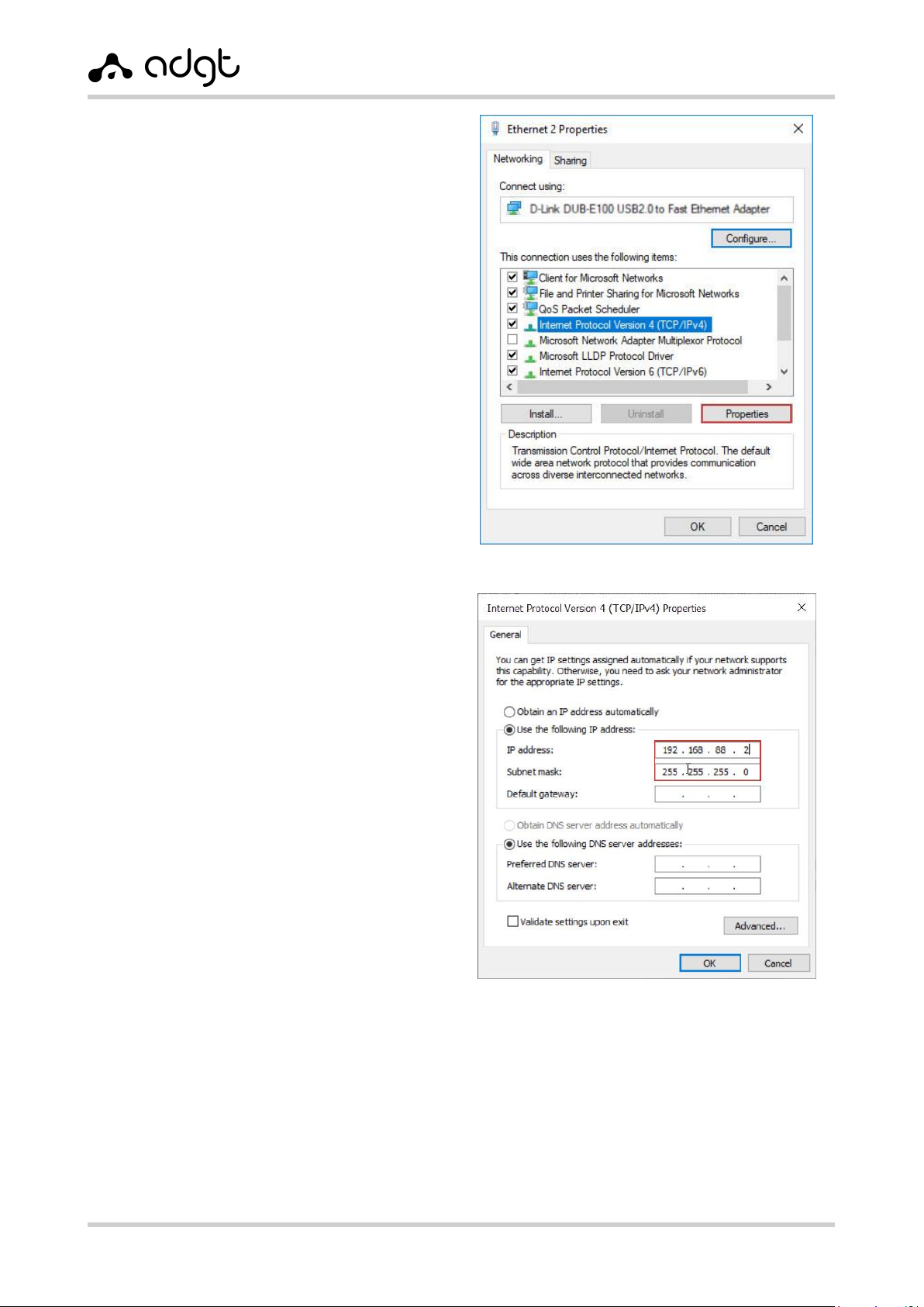
4. In the dialog box that opens, select the item
Internet Protocol version 4 (TCP/IPv4)
and click Properties button.
5. In the protocol settings, select Use
following IP address and fill the lines IP-
address and Subnet mask manually.
The IP-address for local connection must
belong to the same subnet as the IP-address
of the converter. The converter has the
following default settings:
•IP-address: 192.168.88.1
•Subnet mask: 255.255.255.0
Accordingly, the IP-address in the connection
settings must be the same as the address of
the converter, except for the last digits. The
last digits can be any from 0 to 254 (except 0
and 254) as, for example:
•IP-address: 192.168.88.2
•Subnet mask: 255.255.255.0
Note: if the converter is connected to the network directly, it is not necessary to specify the Default
gateway. If the converter is located in the subnet which differs from the PC's one, the IP-address of
the converter must be specified as the gateway.
6. Click OK. If the connection was successful, you can proceed to configuring the device through the
web interface.
Fig. 6. Internet Protocol version 4 (TCP/IPv4).
Fig. 7. Configuring the IP-address of the local connection.
EDM Serial-to-Ethernet Converters
User Guide ver. 2.0 | 2021-09-01
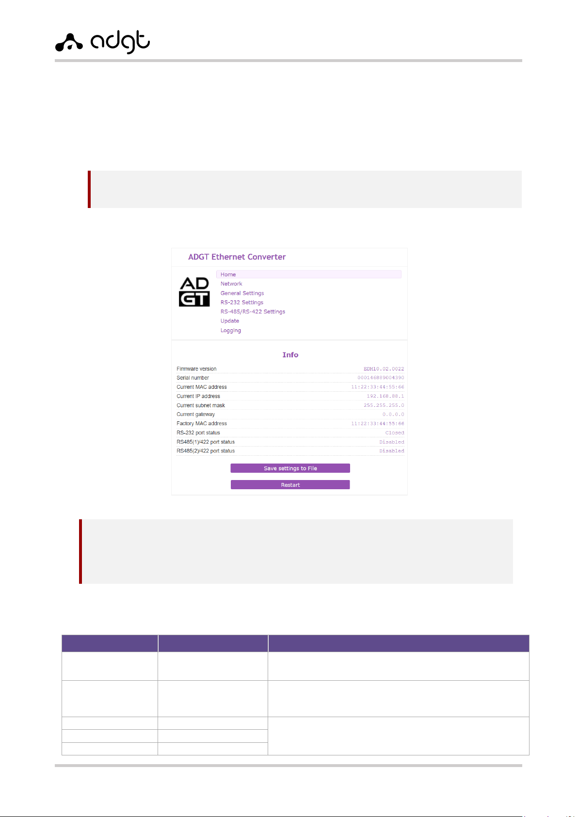
Configuring converter parameters
1. Launch the browser and go to the device configuration page by IP-address 192.168.88.1, after
which the authorization window will open.
2. Enter your username and password to enter the web interface. Default authorization data are:
username –adgt
password –adgt
After the successful authorization, the main page of the web interface with the current settings of
the device will appear in the browser window.
3. In the Network menu, configure the Ethernet network settings and save changes using
Submit button.
Table 5. Network settings.
Parameter
Default value
Possible values
MAC-address
Use factory
Use factory - indicated on the sticker of the case
Set manually
IP-address
192.168.88.1
Use the following IP address - static address,
default one or manually entered one
Obtain automatically - from DHCP-server
Subnet mask
255.255.255.0
Default gateway
0.0.0.0
DNS server address
0.0.0.0
Attention! After three incorrect attempts to enter a username / password, access to the device will
be blocked for 30 seconds.
NOTES:
You can set a new password in the General settings menu.
If the current settings of the device are unknown, it is necessary to reset the settings to the
factory values (see Reboot and factory reset).
Fig. 8. Converter EDM106. Main page of web interface.
EDM Serial-to-Ethernet Converters
User Guide ver. 2.0 | 2021-09-01
4. In the RS-232 Settings and RS-485/RS-422 Settings menues, configure parameters of the serial
ports in accordance with the settings of the connected equipment. For each port, select the
operating mode Client or Server and set its parameters.
Save changes using the Submit button.
Table 6. Configuring serial ports.
Parameter
Default value
Possible values
RS-232
RS-485/RS-422
State
Enabled
--------
Closed
in menu Home
Disabled port 1
and port 2
--------
Disabled
in menu Home
RS-232: disabled/enabled
RS-485: disabled port 1 and port 2/
enabled port 1/
enabled port 2/
enabled port 1 and port 2
RS-422: disabled port 1 and port 2/
enabled port RS-422
Operation mode “TCP-server” (default)
Port number
60001
RS-485(1): 60002
RS-422: 60002
RS-485(2): 60003
Number of TCP-port of server
List of allowed Client
IP-addresses (IP1-IP5)
0.0.0.0
(“White” list disabled,
all connections are allowed)
“White” list of IP-addresses of clients (up to
5 addresses), which are allowed to connect
the converter, when it operates in the
"Server" mode
Maximum number of
incoming connections
2
2, 1
Operation mode “TCP-client”
Port number
60001
RS-485(1): 60002
RS-422: 60002
RS-485(2): 60003
Port of TCP-server, to which the connection
will be made
Server IP address
0.0.0.0
(not specified)
IP-address of server, to which the
connection will be made
Authorization type
No authorization
No authorization, ADGT
Serial number
Each port has its own serial number
15-digit number for registration on the
server (when choosing an authorization
type ADGT)
Clearing the input buffer
on connection
not clear
not clear, clear
Maximum TCP Packet
Length
1024 byte
1 –1024 byte
Force Transmit Timeout
10 ms
1 –10000 milliseconds
Inactivity Time
30 sec
1 –216000 seconds
Ping IP Address
0.0.0.0
(connection check disabled)
To enable connection check, specify the IP-
address to ping the connection (ICMP-echo)
Ping Request Frequency
30 sec
10 seconds –43200 seconds
Flow Control
Disabled
Enabled, Disabled
Baud Rate
9600
600-115200 bit/sec
Data bits
8
8, 7
Parity
No check
Even, Odd, No check
Stop bits
1
1, 0.5, 1.5, 2
EDM Serial-to-Ethernet Converters
User Guide ver. 2.0 | 2021-09-01
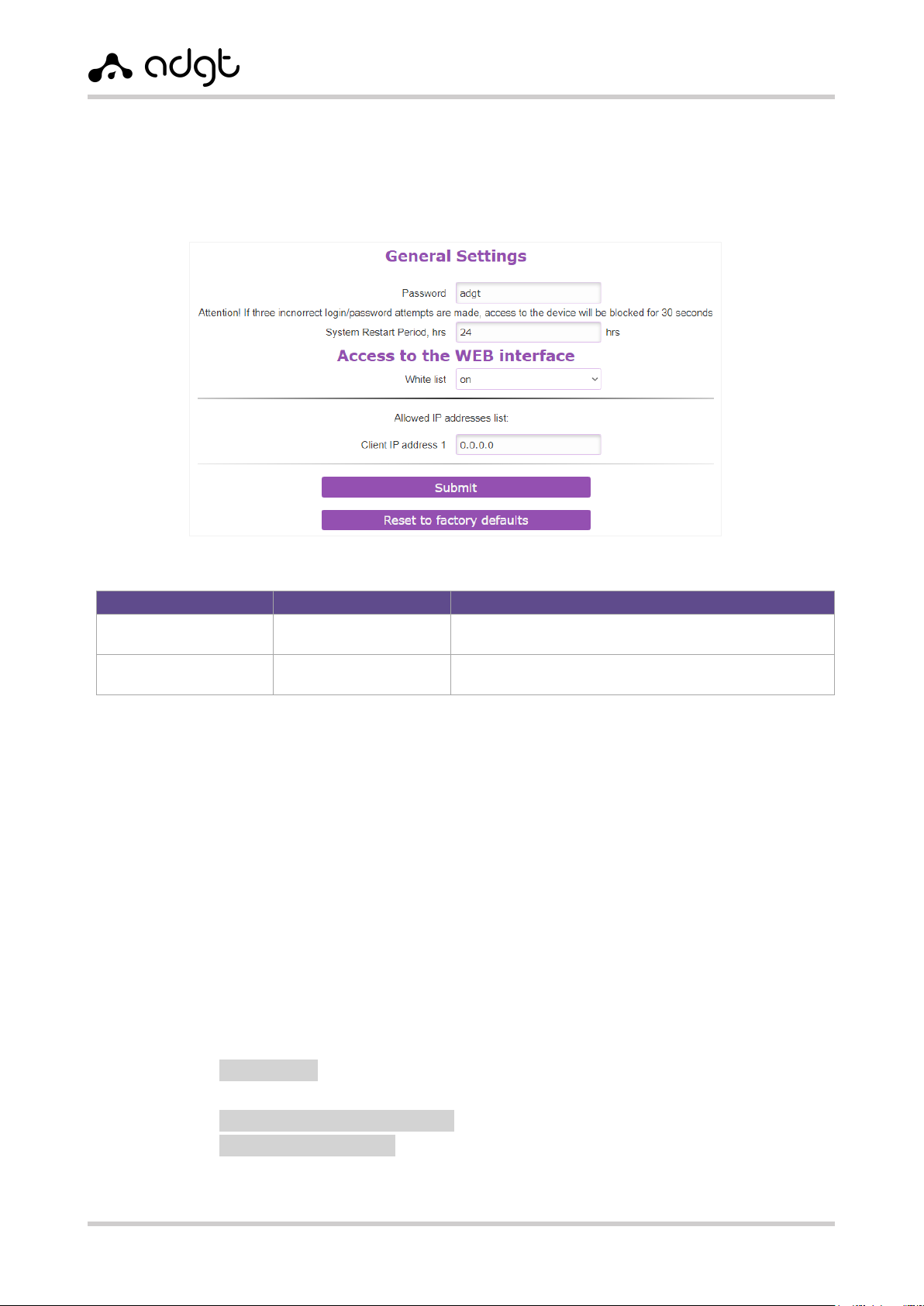
5. In the General settings section, you can, if necessary:
set a new password to access the converter settings;
set the time of periodic system reboot of converter (in hours);
reset converter settings to factory values;
specify a white list of IP-addresses.
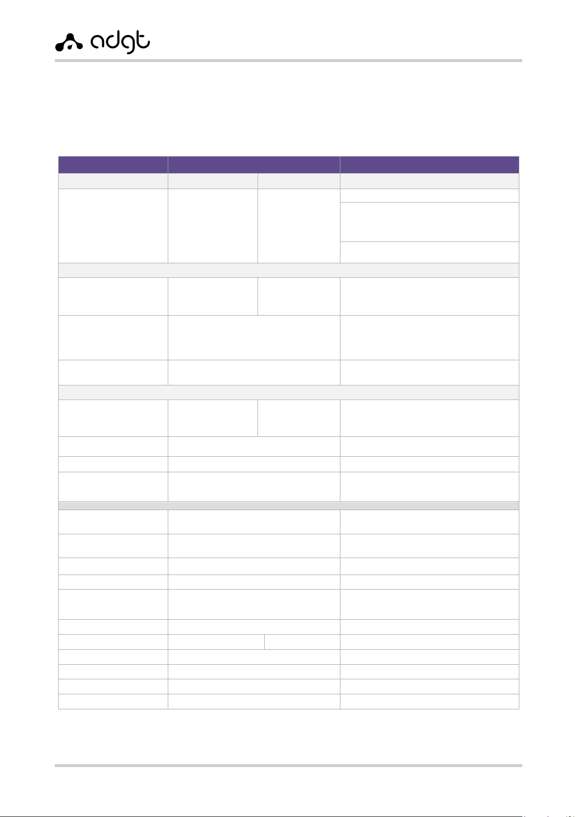
Table 7. General settings.
Parameter
Default value
Possible values
Password
adgt
from 1 to 10 characters
(Latin letters of different case, numbers)
System reboot timeout
24 hours
from 0 (disabled) to 168 hours (7 days)
Step - 1 hour.
Configuring Converter via Console port (RS-232)
In cases where access to the converter via Ethernet is not possible, the device can be configured
through the RS-232 console port (COM-port):
1. Connect the converter to the PC using a console cable with a DB-9F – DB-9M connector.
Connect one end of the cable to the DB-9F connector of the converter, connect the other end
to the COM port on the PC. If your computer does not have a COM port, use a COM-USB
converter. The COM-port number of the connected device can be seen in the section Device
Manager Ports (COM & LPT).
2. Switch the converter to console mode: press RESET button on the device case and hold it
pressed for at least 3 seconds. In console mode, RS-232 port operates at speed of 115200 bps.
3. Open any terminal program on your PC, for example PuTTY. In the connection window, select
Serial connection, enter the COM-port number of the converter, the port speed (115200)
and click Open.
4. To access the settings in the console window, enter the password (default – adgt):
passw adgt
The responce will be:
Authorization successful — if the password is correct;
Incorrect password — if the password is wrong.
For a list of commands for reading and changing the parameters, see Appendix 1. List of commands
for configuring the converter through the console port.
Fig. 9. Web interface of converter. General settings.
EDM Serial-to-Ethernet Converters
User Guide ver. 2.0 | 2021-09-01
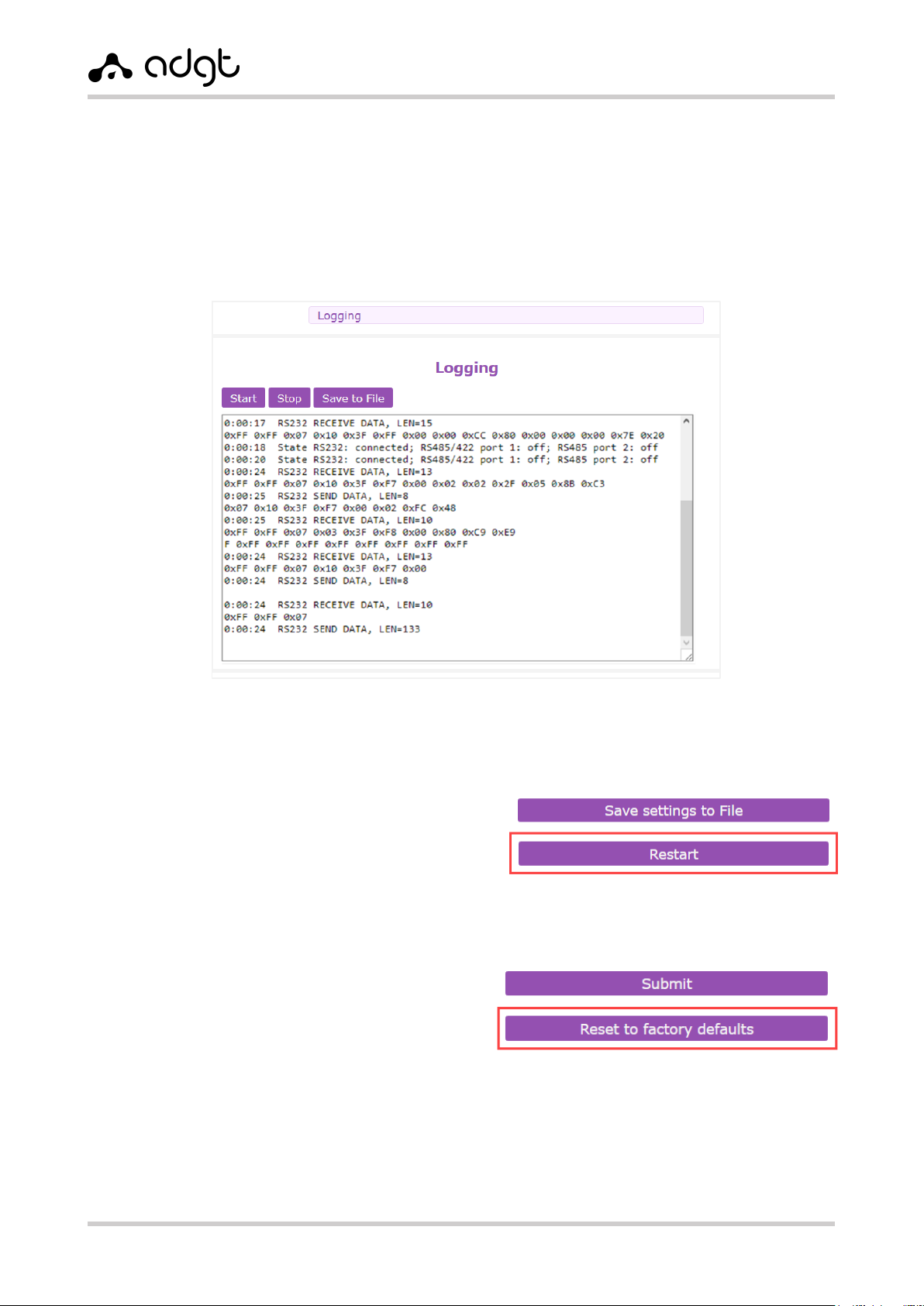
Reading Logs
You can view the converter logs in the web interface in the Logging menu (Fig. 10). The debug window
displays information about the operating modes and status of serial ports, states of connection and
authorization, connection errors, the amount of received data, etc.
Log output can be started (by Start button), interrupted (by Stop button), as well as saved into .txt text
file (by Save to file button).
Reboot and factory reset
Rebooting converter
To reboot the device click Restart button in
the Home menu.
Reset to factory settings
You can perform a factory reset in two ways:
Via web interface:
In the General settings menu, click the
Reset to factory defaults button.
With the RESET button:
To reset the settings, press the RESET button on the device housing with a thin object simultaneously
with turning on the power and hold the button pressed for about 5 seconds.
Fig. 10. Debug messages.
Fig. 11. Rebooting the converter.
Fig. 12. Settings reset.
EDM Serial-to-Ethernet Converters
User Guide ver. 2.0 | 2021-09-01
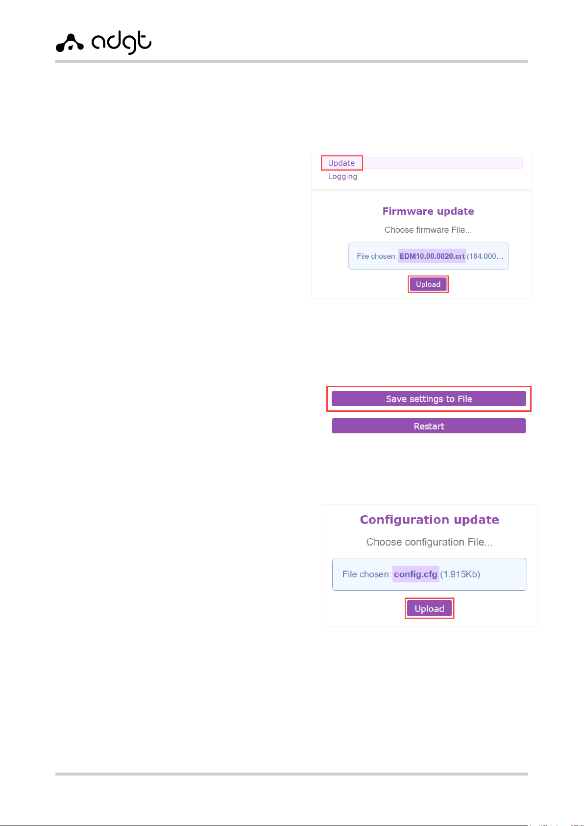
Firmware and Configuration Updates
Firmware update
To update the firmware version of the converter:
1. Download the archive with the current
firmware version from the website adgt.cz.
2. In the menu Update → Firmware update,
specify the path to the firmware file with the
extension .crt and click Upload.
3. After the firmware is updated, the
message File is successfully uploaded.
Rebooting is in progress appears, and
you will be automatically redirected to the
main page of the web-interface.
Saving and Restoring the Configuration Settings
To save the current settings into a separate file
(configuration file), in the Home menu click
Save settings to File button and save the file
with the .cfg extension into a folder on
your PC.
To restore the settings from a file, specify the
path to the .cfg file in the Update →
Configuration update menu, and click the
Upload button.
Fig. 13. Converter firmware update.
Fig. 14. Saving the configuration file.
Fig. 15. Restoring the configuration from file.
EDM Serial-to-Ethernet Converters
User Guide ver. 2.0 | 2021-09-01
Appendix 1. List of commands for configuring converter
via the console port
When operating the converter through the console port, the user can both read and change the current
converter settings. The list of commands is given in the Table 8.
To access the settings in the console window, enter the password (default – adgt):
passw adgt
The responce will be:
Authorization successful — if the password is correct;
Incorrect password — if the password is wrong.
To request the parameter value, enter the command: get, space, parameter name. For example,
get rs485_2_port
To change the value of a parameter, enter the command: get, space, parameter name, space,
parameter value. If the value is within the allowed limits, it will return in response Set OK. For example,
set fixed_ip 192.168.88.1
Table 8. List of commands for configuring the converter.
Command
Description
Note
Feature2
/?
help
List of available commands
R
curr_gw
Current network gateway
R
curr_ip
Current IP-address
R
curr_mac
Current MAC-address
R
curr_mask
Current subnet mask
R
def_mac
Factory MAC address
R
dhcp_client
Use set IP-address or get it from
DHCP
0 –set,
1 –from DHCP
R/W
firmware
SW version
R
fixed_dns
DNS-server address
R/W
fixed_gw
Defined default gateway
R/W
fixed_ip
Manually defined IP-address
R/W
fixed_mask
Defined net mask
R/W
mode_rs485
State of interface
RS485/RS-422
0 –Disabled port 1 and port 2
1 –Enabled port 1
2 –Enabled port 2
3 –Enabled port 1 and port 2
4 –Enabled port RS-422
R/W
password
Password to access settings
from 1 to 10 characters (latin
letters of different case, numbers)
R/W
Settings of RS-232 interface
rs232_auth
Authorization type
0 –no autorization
1 –authorization ADGT
R/W
rs232_baud
Interface port speed
from 600 to 115200 bit/sec
R/W
rs232_check_period
Ping Request Frequency
from 10 to 43200 seconds
R/W
2
R – read-only command, R/W – read and write command.

EDM Serial-to-Ethernet Converters
User Guide ver. 2.0 | 2021-09-01
rs232_check_port
Server port number to check TCP
connection
R/W
rs232_check_server
Server IP address to check TCP
connection
R/W
rs232_flow_control
Flow control
0 –Disabled
1 –Enabled
R/W
rs232_idle_time
Inactivity Time
from 1 to 216000 seconds
R/W
rs232_ip_client1
Allowed IP-address of Client 1 for
Server mode
The same way
for Clients 2-5
R/W
rs232_mode
Operation mode
0 –Client
1 –Server
R/W
rs232_parity
Parity
1 –even
2 –odd
0 –no check
R/W
rs232_port
Port number
R/W
rs232_power
State
0 –Disabled
1 –Enabled
R/W
rs232_remote
Interface state
Disabled, Closed, IP-address, if
connected
R
rs232_serial
Serial number for ADGT authorization
type
R
rs232_server
Server address for Client mode
R/W
rs232_size_pack
Maximum TCP Packet Length
from 1 to 1024 byte
R/W
rs232_stop_bit
Stop bits
0 –1 character
1 –0.5 characters
3 –1.5 characters
2 –2 characters
R/W
rs232_time_wait_pack
Force Transmit Timeout
from 1 to 10000 milliseconds
R/W
rs232_world
Data bits
0 –8 bit
1 –7 bit
R/W
Settings of RS-485/RS-422 interface, port 1
rs485_1_auth
Authorization type
0 –No authorization
1 –ADGT authorization
R/W
rs485_1_baud
Interface port speed
from 600 to 115200 bit/sec
R/W
rs485_1_check_period
Ping Request Frequency
from 10 to 43200 seconds
R/W
rs485_1_check_port
Server port number to check TCP
connection
R/W
rs485_1_check_server
Server address to check TCP
connection
R/W
rs485_1_flow_control
Flow control
0 –Disabled
1 –Enabled
R/W
rs485_1_idle_time
Inactivity Time
from 1 to 216000 seconds
R/W
rs485_1_ip_client1
Allowed IP-address of Client 1 for
Server mode
The same way
for Clients 2-5
R/W
rs485_1_mode
Operation mode
0 –Client
1 –Server
R/W
rs485_1_parity
Parity
1 –even
2 –odd
0 –no check
R/W
rs485_1_port
Port number
R/W
rs485_1_remote
Interface state
Disabled, Closed, IP-address, if
connected
R
rs485_1_serial
Serial number for ADGT type of
authorization
R
rs485_1_server
Server address for Client mode
R/W
rs485_1_size_pack
Maximum TCP Packet Length
from 1 to 1024 byte
R/W
rs485_1_stop_bit
Stop bits
0 –1 character
1 –0.5 characters
3 –1.5 characters
2 –2 characters
R/W

EDM Serial-to-Ethernet Converters
User Guide ver. 2.0 | 2021-09-01
rs485_1_time_wait_pack
Force Transmit Timeout
from 1 to 10000 milliseconds
R/W
rs485_1_world
Data bits
0 –8 bit
1 –7 bit
R/W
Settings of RS485/422 interface, port 2
rs485_2_auth
Authorization type
0 –No authorization
1 –ADGT authorization
R/W
rs485_2_baud
Interface port speed
from 600 to 115200 bit/s
R/W
rs485_2_check_period
Ping Request Frequency
from 10 to 43200 seconds
R/W
rs485_2_check_port
Server port number to check TCP
connection
R/W
rs485_2_check_server
Server address to check TCP
connection
R/W
rs485_2_flow_control
Flow control
0 –Disabled
1 –Enabled
R/W
rs485_2_idle_time
Inactivity Time
from 1 to 216000 seconds
R/W
rs485_2_ip_client1
Allowed IP-address of Client 1 for
Server mode
The same way
for Clients 2-5
R/W
rs485_2_mode
Operation mode
0 –Client
1 –Server
R/W
rs485_2_parity
Parity
1 –even
2 –odd
0 –no check
R/W
rs485_2_port
Port number
R/W
rs485_2_remote
Interface state
Disabled, Closed, IP-address, if
connected
R
rs485_2_serial
Serial number for authorization ADGT
R
rs485_2_server
Server address for Client mode
R/W
rs485_2_size_pack
Maximum TCP Packet Length
from 1 to 1024 byte
R/W
rs485_2_stop_bit
Stop bits
0 –1 character
1 –0.5 characters
3 –1.5 characters
2 –2 characters
R/W
rs485_2_time_wait_pack
Force Transmit Timeout
from 1 to 10000 milliseconds
R/W
rs485_2_world
Data bits
0 –8 bit
1 –7 bit
R/W
Basic settings
time_reboot
Non-conditional reset timer,
in hours
0 –Disabled
1–168 –Enabled, in hours
R/W
user_mac
User-defined MAC-address
0 –Use factory set
1 –Set user-defined one
R/W
utilize_user_mac
Which MAC-address to use
ADGT systems s.r.o.
Planichkova, 442/3, 16200, Prague 6, Prague, CZ
phone: +420 538 890 720
www.adgt.cz, e-mail: [email protected]
This manual suits for next models
1
Table of contents
Popular Media Converter manuals by other brands


H&B
H&B TX-100 Installation and instruction manual

Bolin Technology
Bolin Technology D Series user manual

IFM Electronic
IFM Electronic Efector 400 RN30 Series Device manual

GRASS VALLEY
GRASS VALLEY KUDOSPRO ULC2000 user manual

Linear Technology
Linear Technology DC1523A Demo Manual

Lika
Lika ROTAPULS I28 Series quick start guide

Weidmuller
Weidmuller IE-MC-VL Series Hardware installation guide

Optical Systems Design
Optical Systems Design OSD2139 Series Operator's manual

Tema Telecomunicazioni
Tema Telecomunicazioni AD615/S product manual

KTI Networks
KTI Networks KGC-352 Series installation guide

Gira
Gira 0588 Series operating instructions

Lika
Lika SFA-5000-FD user guide