ADI AM580 User manual

4x256 Memory Channels
CTCSS/DCS/2TONE/5TONE
DTMF-ANI/5TONE-ANI
Compander
Detachable Front Panel
AM580
USER'S MANUAL
FCC ID:RIQAM-580

Congratulations!
First of all, thank you for purchasing this mobile radio transceiver proudly made by ADIC. We
carefully built this device to be user-friendly, ruggedly durable, and high quality. The device is built with a cooling fan to
provide stability during high output transmission; it also has four channel modes of UV, VU, VV, and UU. AM-580 has 758
memory channels, full duplex mode, detachable front panel, and many other features waiting for you to explore!
Please take a few minutes to read this manual carefully. The information provided here will allow you to derive
maximum performance from the radio.
We’re glad you are part of the ADIC team now. Contact us anytime if you have any comments or enquiry, because
your satisfaction is our No.1 priority!
NOTE:
1. Please DO NOT operate the device while driving.
2. AVOID long period of continuously operation under high output as it may cause overheat to the device. Make sure the
surface of the device is not in contact with plastics or other flammable objects to avoid any possible dangers.
3. The device is designed for use with 13.8V DC; please DO NOT use 24V DC to avoid damage to the device.
4. Please DO NOT keep the device under a dusty or humid circumstance, and please do not place the device on an
uneven platform.
5. If interference occurs, please move the device away from the source of interference such as TV, power generators and
etc.
6. If smoke or odor came out from the device, please TURN OFF the power immediately. Please contact your dealer or
ADIC service team.
Disclaimer:
Changes or modifications to this transceiver, not expressly approved by ADIC Corp., could void your authority to operate
this transceiver under FCC regulations.

CONTENTS
Supplied Accessories .
.........................4
Supplied Accessories..............................................................4
Initial Installation .......................................................................4
Mobile installation ...................................................................4
DC Power Cable Connection ..................................................5
Antenna Connection ...............................................................6
Accessories Connections........................................................7
Getting Acquainted ...................................................................8
Front panel..............................................................................8
Rear panel ..............................................................................9
DISPLAY .................................................................................9
microphone ...........................................................................10
Basic Operations.....................................................................11
Switching The Power On/Off................................................. 11
Adjusting The Volume .......................................................... 11
Switch between VFO and Channel mode .............................11
Adjusting Frequency .............................................................11
Adjusting Channel.................................................................11
Switch Between Main Band and Sub band...........................12
Selecting the frequency band ...............................................12
Receiving ..............................................................................12
Squelch Off/Squelch Off Momentary.....................................12
Transmitting ..........................................................................12
Shortcut Operations................................................................13
........... 13
Squelch Level Setup .................................................
Transmit DTMF/2TONE/5TONE signaling ............................13
High/Mid/Low Power Switch .................................................13
Frequency Reverse...............................................................13
Band-width Selection ............................................................13
Home Channel ......................................................................13
Hyper Memory channel.........................................................13
Dual Watch............................................................................14
Emergency Alarm..................................................................14
Channel/Frequency Scan .....................................................14
Channel Scan Skip ...............................................................14
Channel Edit .........................................................................14
Scan range Limit ..................................................................14
Channel Copy .......................................................................14
Channel Delete .....................................................................15
General Setting........................................................................16
APO (Automatic Power off)...................................................16
Automatic offset ....................................................................16
Frequency Channel Step Setup............................................16
VFO Band lockout.................................................................17
Beep Function.......................................................................17
CPU Clock frequency Change ..............................................17
2TONE Encode select ..........................................................17
5TONE Encode select ..........................................................18
Add Optional signaling ..........................................................18
CTCSS encode Setup ..........................................................18
CTCSS decode Setup...........................................................19
Sub Band Display Setup .......................................................19
DTMF Encode Pre-Loading time ..........................................19
DTMF Encode Transmitting Time .........................................20
DTMF Encode setup .............................................................20

.........20
........................21
................21
21
..........22
.................23
......23
..........23
...........23
.........24
.......24
.............................24
......................25
......25
....25
......25
.........26
......26
...........26
.......27
..........................27
.27
.........27
....28
.............28
.............28
....................28
29
Squelch Mode Setup....................................................
Compander ...................................................
Scrambler Setup ...................................................
Tone Burst (Pilot Frequency) ................................................
Keypad Mode Setup ...................................................
Keypad Lockout ...................................................
TX OFF (PTT Lockout) ...................................................
Squelch Level setup....................................................
Frequency Reverse....................................................
Sub band mute setup...................................................
Editing Channel Name ...................................................
Channel Function Auto Storage Setup ....
Microphone PA,PB, PC,PD key setup ............
RF Squelch level setup ...................................................
OFFSET Direction setup...................................................
Scan Dwell Time Setup...................................................
Priority channel scan....................................................
Offset frequency Setup ...................................................
Display mode Setup...................................................
Busy Channel Lockout ...................................................
Radio's DTMF SELF ID ENQUIRY .............
5TONE SELF ID ENQUIRY.................................................
TOT (Time-out timer) ...................................................
VFO Frequency Linkage ...................................................
Wide/Narrow band ...................................................
Cross Band repeat ...................................................
LCD backlight....................................................
Keypad backlight brightness .................................................
Calling Record ......................................................................29
AM Function..........................................................................29
Automatic AM function ..........................................................29
VHF External speaker port....................................................30
BEEP Volume control ..........................................................30
Talk Around........................................................................... 30
Microphone speaker............................................................. 30
Password Function ...............................................................30
Microphone Operation ............................................................31
Send DTMF signaling ...........................................................31
Main/Sub band switching ......................................................31
Function operation through PA-PD keys...............................31
Cable Clone..............................................................................33
Resume Factory Default .......................................................33
Programming Software Installing and Starting ....................34
Install USB Cable Driver Programme ...................................34
Maintenance.............................................................................35
Default Value For Factory Resume......................................35
Trouble Shooting...................................................................35
Specications ..........................................................................36
Attached Chart.........................................................................37
51 groups CTCSS Tone Frequency(Hz) ...............................37
1024 groups DCS Code........................................................37
CONTENTS
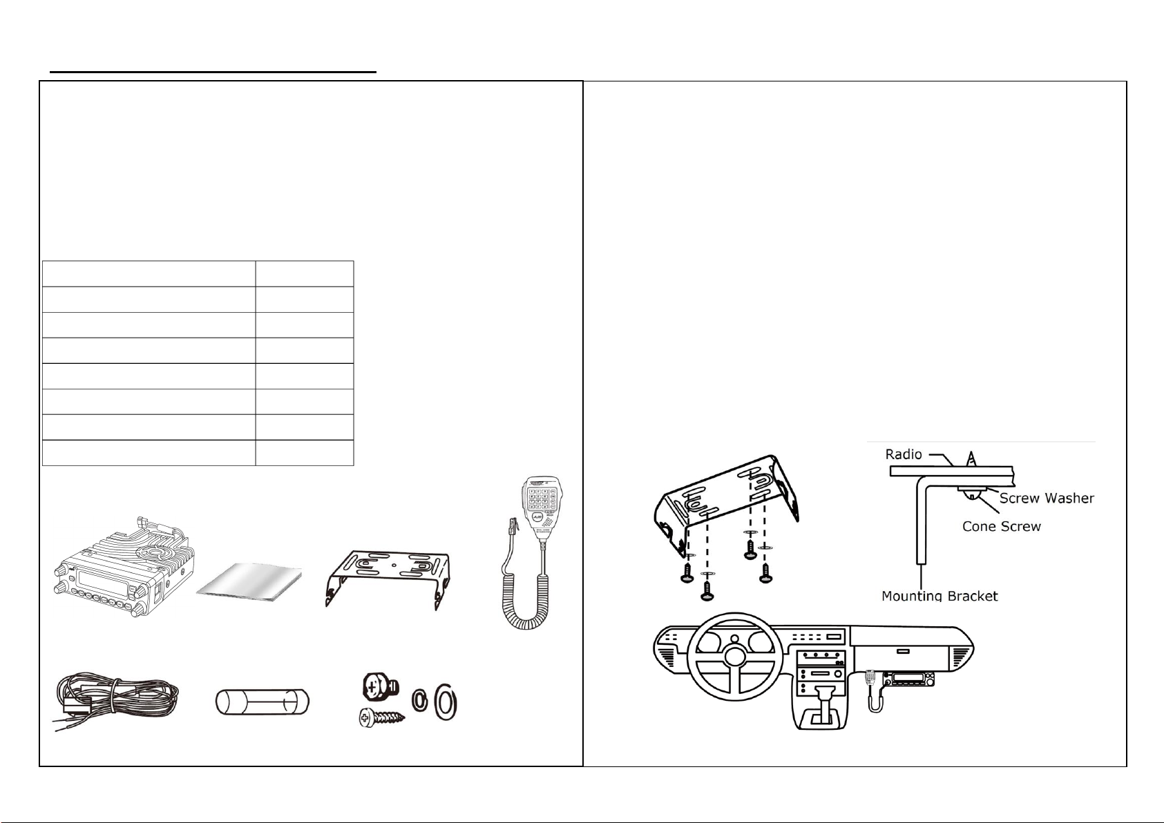
Package Check / Mobile Installation
Thank you for choosing ADIC products. Please carefully
check the package to see if all the contents listed are
included; if anything is damaged or missing please contact
your dealer or ADIC service team. Thank you.
※Content List
Item
Quantity
AM-580 Mobile Radio
1
Handheld Microphone
1
Mounting Bracket
1
DC Power Cable
1
Backup Fuse
1
Screws
1
Manual
1
AM-580 Manual Mounting Bracket H. Microphone
DC Power Cable Backup Fuse Screws
Installation on Vehicle
※Caution
1. For safety, before installing power cable, make sure the
negative charge is removed.
2. After installation is complete, connect the negative charge
back and make sure all the setup is correct.
3. If the fuse breaks, check the power cable and replace the
fuse with the same spec.
4. After the completion of connection, use electrical tape to
wrap the fuse to prevent from heat and humidity.
5. Fuse should not be removed even with excessive length of
power cable.

Use the screw and the washer to assemble the machine to
the mounting bracket, make sure it’s tightened to prevent any
damage caused by loosening.
The design of the mounting bracket allows you to have three
different angles as you desired.
DC Power Cable Installation
※Power Operation
Only connect the device to a 12V DC power source, DO NOT
connect to a 24V power source. Make sure the battery has
enough charge. If the voltage of the battery is low, the
display of the device may be dimmed during transmitting and
the output power may drop instantly.
1. Use the shortest route from the device to the car battery.
- DO NOT use the cigarette-plug in the vehicle
- Layout of the cable should avoid heat, humid spot.
2. After the layout of the cable, use electrical tape to wrap up
the fuse box to avoid humidity, make sure the cables are
stably attached.
3. To avoid short current, remove the negative charge on the
battery then connect the radio.
4. Make sure the charges are correctly connected; red cable
connects to positive charge and black cable connects to
negative charge.
5. Reconnect the negative charge removed earlier from the
battery.
6. Connect the DC power cable to the radio, firmly press until
tightened.
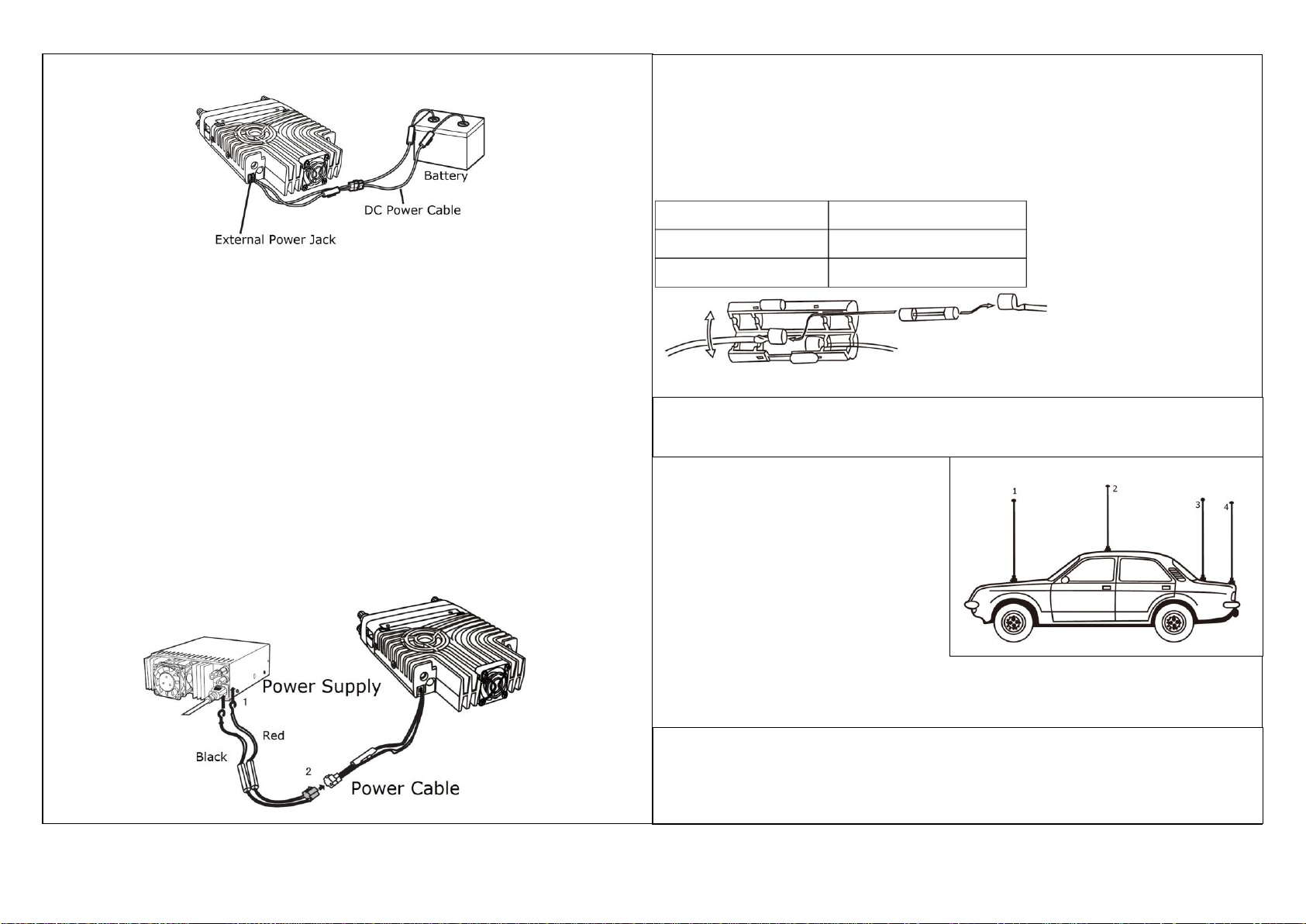
Basic Installation
※Fixed Station Installation
For use of this transceiver as a fixed station, you will need a
13.8V DC power supply. Recommended power supply
current is 12A.
1. Connect the DC power cable to a stable power supply.
Make sure red is connected to positive charge and black is
connected to negative charge.
- DO NOT directly connect the radio to an AC outlet.
- DO NOT substitute a cable with smaller wire gauges.
2. Connect radio’s DC power cable to a power supply cable.
Press firmly to so that it’s tightened.
※Fuse Replacement
If the fuse breaks, check and find out the cause before replacing the
new fuse. If the fuse breaks again, please remove the power cable,
contact your dealer or ADIC service team for assistance.
Fuse Location
Fuse Current Rating
Transceiver
15A
DC Power Cable
20A
*Use only specified fuse current to avoid possible damage to the transceiver.
Antenna Installation
Install appropriate antenna
before operating. Carefully
install the antenna as it will
affect the range of the output.
Use a 50Ωimpedance
low-loss coaxial antenna.
AVOID using the transceiver when the vehicle battery is not fully charged or
when the engine is off, this will cause the vehicle battery to run out.
1. Transmitting without antenna may cause damage to the transceiver.
2. Equip lightning protection for stationed operation to reduce the risk of fire,
electric shock, and damage to the transceiver.

8
4
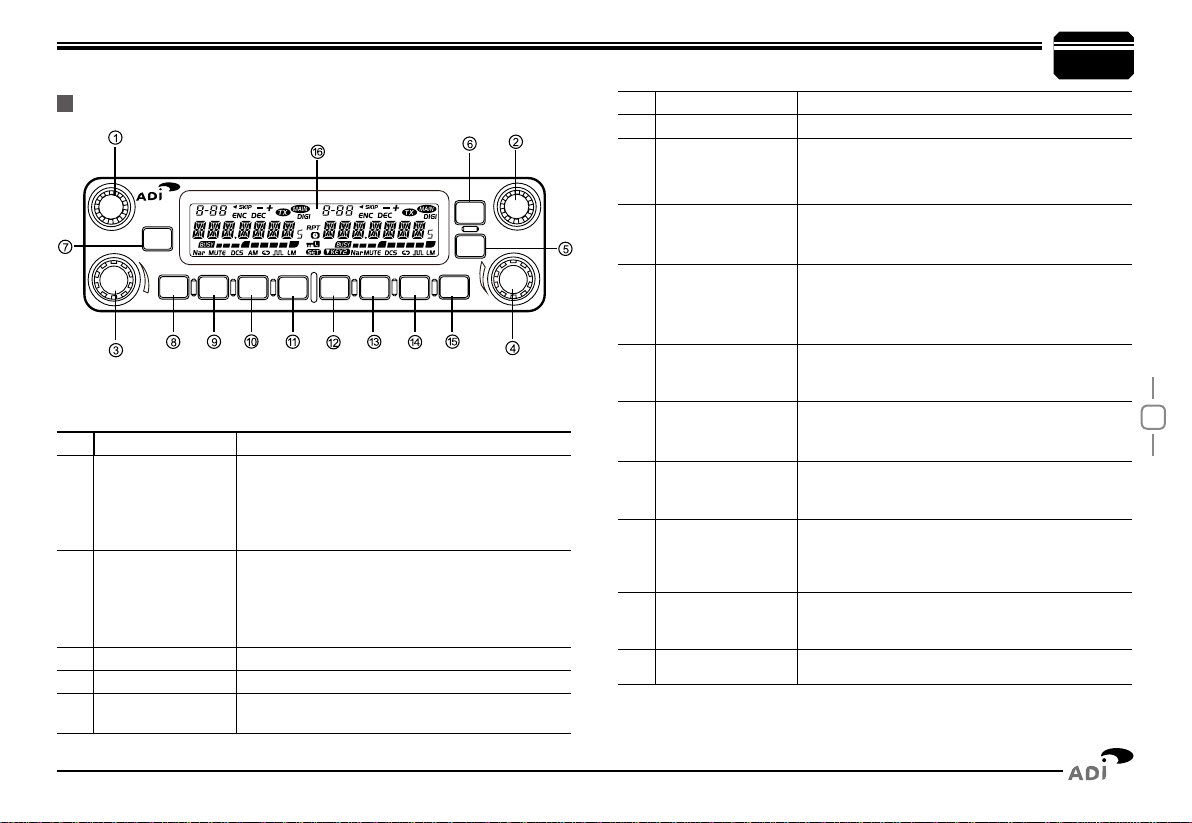
Basic Functions•
NO. KEY FUNCTION
1 Left Dial Knob
Rotate it to choose frequency /channel. Press
it to set the left band as "Main Band"; In VFO
mode, press it to choose the frequency band;
In function setup as conrm key; in scan mode,
rotate it to change scan direction
2 Right Dial Knob
Rotate it to choose frequency /channel. Press
it to set the right band as "Main Band"; In VFO
mode, press it to choose the frequency band;
In function setup as conrm key; in scan mode,
rotate it to change scan direction
3 Left Volume Knob Adjust left band volume level.
4 Right Volume Knob Adjust right band volume level.
5
【
TV/SQL
】
In standby. press this key to turn On/Off TV
function.Hold this key to cancel squelch
Getting Acquainted
FRont pAnel
6 Function set Key In standby , press this key to enter function menu
7 PWR Press it to power On /Off the transceiver
8 Left
【
LOW
】
Key
In standby press it to change H/L power for present
channel.Long press it to turn On/Off
Function
9 Left
【
V/M
】
Key
In standby, press it to switch between channel
mode and VFO mode. Long press it to set Wide/
Narrow band.
10 Left
【
HM
】
Key
In standby, press it to switch between HOME
channel and normal channel. Long press it to
enter dual watch of VFO channel and current
channel.
11 Left
【
SCAN
】
Key
In standby, press it to start channel or frequency
scan.In channel mode, hold it to set current
channel scan skip.
12 Right
【
LOW
】
Key
In standby press it to change H/L power for
present channel.Long press it to turn On/Off
Frequency Reverse Function
13 Righ
【
V/M
】
Key
In standby, press it to switch between channel
mode and VFO mode. Long press it to set Wide/
Narrow band.
14 Righ
【
HM
】
Key
In standby, press it to switch between HOME
channel and normal channel. Long press it to
enter dual watch of VFO channel and current
channel.
15 Righ
【
SCAN
】
Key
In standby, press it to start channel or frequency
scan.In channel mode, hold it to set current
channel scan skip.
16 LCD
For display of channel, frequency and function
setup.
Frequency
Reverse
CH
CH
VOLVOL
POW
LOWV
/MHM SCNLOW V/M HM SCN
TV/SQL
SET

9
4
NO. KEY FUNCTION
1 Ext. Power Jack
Terminal for connecting optional cable QCC01 for
use with ignition key On/Off function.The radio will
auto power on when car is driving. The radio will
auto power off when car stops.
2Ext.Speaker Terminal Terminal for optional external speaker SP02
3 TV/AV port Connect to television TV/AV port. (Optional)
4 Heat -sink fan Runs Automatically when radio temperature rise up.
5 Antenna Connector Connect a 50 Ω antenna
NO. INDICATOR FUNCTION
1Displays the channel number and Menu number.
2Appears when current channel is priority channel
3Appears when current channel is set Scan Skip
4Appears when current channel has CTCSS Encode
5Appears when current channel has CTCSS Decode
6Appears when the Offset function is ON
7Appears while transmitting.
8Displays the Main channel.
9Displays the operating frequency,channel name
10 Displays when receiving a signal or Monitor is ON
11 Signal strength for receiving and power level for
transmitting
12 Appears while in Narrow band.
13 Appears when mute has been turned ON.
14 Appears when the DCS function is ON.
15 Appears while in AM mode
16 Appears when the Scrambler function is ON
17 Appears when the Compander function is ON.
18 Appears while using Low output power
19 Appears while using Middle output power
20 Appears while Auto power off function is ON.
21 Appears when the Key Lock function is ON.
22 Appears when press SET key.
23 Appears when choose KEY2 mode.
24 Appears when corss band repeat function is ON
Getting Acquainted
ReAR pAnel
diSplAY
4 132
1 1
10
11
11
12 1213 1314 1415 1616
21
22
17 1718 1819 19
20
23
24
9
8
2 534 6 7 8
2 534 6 7
99

11
In frequency (VFO) mode, turn the selector
knob clockwise to increase frequency;
counterclock-wise to decrease frequency.
Every gear will increase or decrease
frequency by one step. To adjust the Main
band frequency, press corresponding selector
knob, the left side of decimal point will ash.
In this status, turn the selector knob will increase or decrease frequency
quickly by 1MHz step.
AdjuStinG FRequencY thRouGh SelectoR knob
input FRequencY thRouGh MicRophone nuMbeR keY
In standby, press corresponding key to
switch between Frequency and channel mode,
when the transceiver is in channel mode, the
LCD will display current channel.
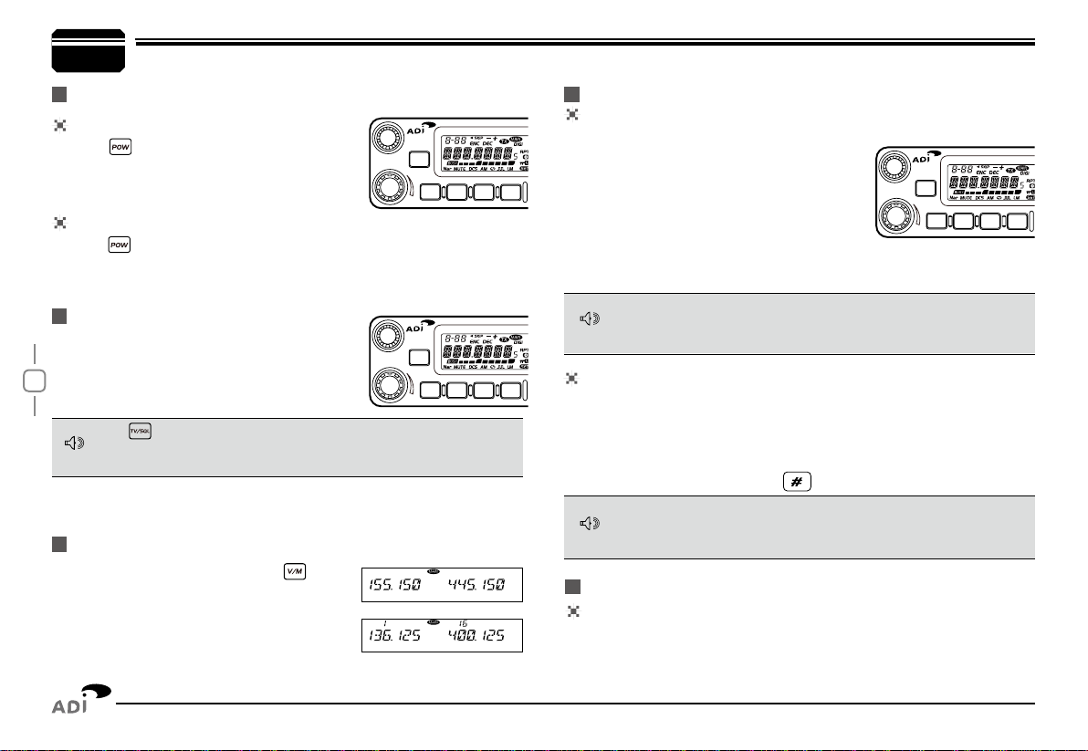
5Basic Operations
poweR on
Press key to switch the transceiver ON,
the LCD displays "WELCOME ", then display
current frequency or channel.
poweR oFF
Press key for over 0.5 Second to switch the transceiver OFF.
Rotate the [VOLUME] knob of selected
band clockwise to increase the volume,
counterclockwise to decrease the volume.
SwitchinG the poweR on/oFF
AdjuStinG the VoluMe
Switch between VFo And chAnnel Mode
AdjuStinG FRequencY
Hold , keep pressing it to Monitor the background noise after the
transceiver emits a DU beep, meanwhile adjust the [VOLUME] knob.
During communication, volume can be adjusted more accurate.
The microphone [UP/DOWN ]key also able to adjust frequency.
Press [ UP/DOWN ]key will increase(decrease) the frequency by one
step size. Hold [UP/DOWN ]key will adjust the frequency continuously.
When the Band lockout function is on, the input or adjusting of frequency
bandwill limit within the current VFO band. The right band only limited in
136-174Mhz and 400-470Mhz.
In VFO mode, you can input the frequency by the microphone numeric
key. It is invalid to input frequency out of the frequency band.
For example:
to input 150.125Mhz, press 1, 5, 0, 1, 2, 5 continuously.
to input 152 MHz, press1, 5, 2, continuously.
AdjuStinG chAnnel
AdjuStinG chAnnel thRouGh SelectoR knob
In channel mode, you can adjust the channel directly by the channel
knob.Turn clockwise to increase one channel; turn counterclockwise
to decrease one channel.To adjust the Main band channel, press
NOTE
NOTE
NOTE
CH
VOL
POW
LOWV
/
MHM SCN
CH
VOL
POW
LOWV
/
MHM SCN
CH
VOL
POW
LOWV
/
MHM SCN
12
Switch between MAin bAnd And Sub bAnd
SelectinG the FRequencY bAnd
If there is any empty channel, the adjustment will ignore it and jump to
next channel.
This transceiver can be set working on 2 UHF band or 2 VHF band.
input chAnnel thRouGh MicRophone nuMbeR keY
In channel mode, you can switch to desired channel by press 3 of the
microphone numeric keys (001-758). For example input 001 get channel 1;
input 030 is channel 30; input 512 is channel 512. If the input channel is
not programmed with frequency, the transceiver will emit a warning beep
and return to last channel.
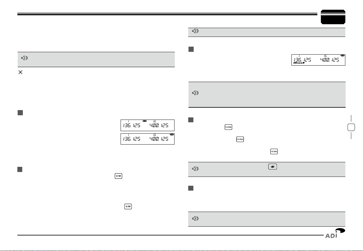
This transceiver is default on dual receive,
a "MAIN" icon will display in the top right of
the working frequency. The transmitting is
only available on the Main band. When the left
Band is Main band, press the right selector
knob will switch the right Band to Main band. Then press the left selector
knob will switch the left Band to Main band.
1. Choose for Left band: press the left side key to switch it to VFO
mode, press the left selector knob over 1 second then repeat above
operation will switch the left band between 108~180Mhz (RX: 108-
174Mhz, TX: 136-174Mhz), 220~260Mhz (RX only), 350~399.995Mhz
(RX only) or 400~490Mhz.
2. Choose for right band: press the right side key to switch it to
VFO mode, press the right selector knob over 1 second then repeat
above operation will switch the right band between 136-174Mhz,
400~490Mhz.
5
Basic Operations
ReceiVinG
If the transceiver has set at higher squelch level, it may fail to hear the
calling. If the “BUSY” and signal strength icon display in left band or
right band, but can not hear the calling, means the signal is with matching
carrier but dis-matching signaling.
In standby, both left band and right band are
able To receive. When they receive any signal,
the “BUSY” icon and signal strength icon will appear in the corresponding
area of the LCD. And you can hear the calling.
Squelch oFF/Squelch oFF MoMentARY
Long press of key can be programmed as Squelch Off or Squelch
Off Momentary to monitor the weak signal.
1. Squelch Off: Hold key until hear "Du" beep, the squelch is off,
repeat the above operation to resume squelch.
2. Squelch Off Momentary: Keep hold key to disable squelch, release
the key to resume squelch.
tRAnSMittinG
Hold “PTT” key, the transceiver change to transmitting. Please hold
the Microphone approximately 2.5-5.0cm from your mouth, and then
speak into the microphone in your normal voice to get best timbre.
The transmitting only available on Main band, the “TX” icon will display in
the top right corner of the Main band frequency.
In standby, press the microphone to cancel squelch, press it again to
turn on the squelch.
correspondent selector knob, the channel number flashes in this
situation, the channel number will increase 10 channels by each gear of
selector knob. Press microphone [ UP/DOWN ]key also able to adjust
the channel.
NOTE
NOTE
NOTE
NOTE
NOTE
13
6Shortcut Operations
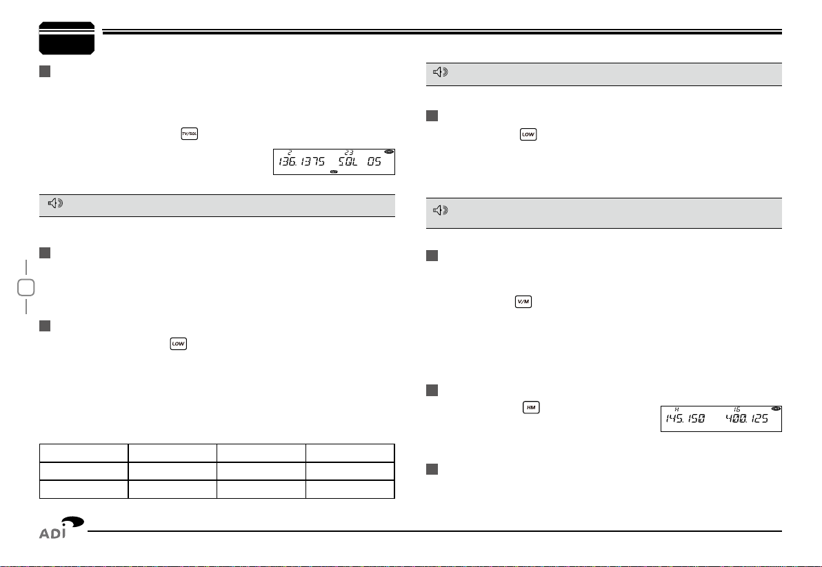
Squelch leVel Setup
This function is used to setup the strength of receiving signal, when the
strength reach a certain level, the calling can be heard, otherwise, the
transceiver will keep mute.
In standby, press and hold key, meanwhile switch the selector knob
to adjust the squelch level of Main band.
1-20: Total 20 squelch levels available.
OFF: turn off squelch. The background noise always on.
The squelch level shall setup separately for right band and left band.
tRAnSMit dtMF/2tone/5tone SiGnAlinG
If the current channel is with DTMF/2TONE/5TONE signaling, hold PTT
and [ UP ]key will transmit selected Pre-programmed signaling
hiGh/Mid/low poweR Switch
In standby, repeat press key to choose power levels as following:
When LCD displays HIGH, the power for current channel is high.
When LCD displays MID1, the power for current channel is middle 1
When LCD displays MID2, the power for current channel is middle 2.
When LCD displays LOW, the power for current channel is low.
Output power for each level:
HIGH MID1 MID2 LOW
VHF(50W) VHF(20W) VHF(10W) VHF(5W)
UHF(40W) UHF(25W) UHF(10W) UHF(5W)
In channel mode, this operation is for temporary use only
This function is valid only when current channel setup with offset frequency
and offset direction
In standby, press key to switch to HOME
channel, and communicate on HOME channel.
repeat pressing it to return to last channel.
In standby, hold key for over 0.5second to turn On/ Off frequency
reverse function. When reverse function is on, the TX frequency will
change to RX frequency and RX frequency change to TX frequency.
The signaling will also be reversed if CTCSS/DCS signaling existed in
this channel.
hoMe chAnnel
FRequencY ReVeRSe
This transceiver has 3 band widths, select suitable band width in
accordance with different local conditions.
In standby, hold key for over 0.5 second to choose the 3 band widths
When LCD displays WIDE, current channel is working on wide band
25KHzWhen LCD displays MIDDLE,current channel is working on middle
band 20KHzWhen LCD displays NARROW, current channel is working on
narrow band 12.5KHz
bAnd-width Selection
NOTE
NOTE
NOTE
hYpeR MeMoRY chAnnel
In standby, press the left or right volume knob will switch the radio work
on hyper channel 1 or hyper channel 2.

14
Shortcut Operations
In standby, hold key for over 0.5 second to enter Dual Watch
mode. The radio will scan the channel in every 5 seconds. When the radio
receives matching signal, it pause scanning until the signaling disappear.
Repeat above operation to exit Dual watch.
duAl wAtch
FRequencY ScAn
chAnnel/FRequencY ScAn
In VFO mode, this function is designed to monitor signal of every
communicative frequency point of "step size" you have set.
In VFO mode, press the Main Band
1. key to enter channel scan.
During the scanning adjust the Main band selector knob or press
2.
microphone [ UP/DOWN ] key will change the scan direction.
Press
3. key to exit scan.
chAnnel ScAn
In channel mode, press the Main Band
1. key to enter channel scan.
During the scanning, adjust the Main band selector knob or press
2.
microphone [ UP/DOWN ] key will change the scan direction.
Press
3. key to exit scan.
In channel mode, switch selector knob to choose the channel, then hold
In VFO mode, turn selector knob to select the desired frequency or
1.
input frequency by MIC's numeric keys.
Hold
2. key until the transceiver prompt
DU and the display of channel number ashes.
Turn selector knob to select the channel number to store. (If the
3.
storage has data , the LCD will display the
frequency, otherwise will display"----------")
Press
4. key, the LCD display MEN- IN, the channel edit completed.
In channel mode, turn the selector knob to choose the channel.
1.
Hold
2. key until the transceiver prompt a Du and channel number
display ashes.
Turn selector knob to choose channel number for storage. ( If the
3.
chAnnel ScAn Skip
chAnnel edit
chAnnel copY
6
eMeRGencY AlARM
To start emergency alarm, hold the right volume knob until the trans
-ceiver displays ALARM and emit alarm. Re-power on the transceiver to
exit alarm. This transceiver has 4 kind of alarm which can be setup by
programming software.
6
for over 0.5 second, the radio prompts
"DU DU", and LCD displays "SKIP", and now
the current channel is Scan Skip.
ScAn RAnGe liMit
You can set the VFO scan frequency range by this function:
Choose upper limit and lower limit frequency, there are L1/U1- L5/
1.
U5, five couple of limit frequency for selection. L stands for lower
limit and U stands for the upper limit. the upper limit must over the
lower limit frequency. Please refer to the
Channel Edit to setup the limit frequency.
In VFO mode, set the VFO frequency in
2.
the range between upper and lower limit.
Press
3. key to start scan in lmited range.
15
Shortcut Operations
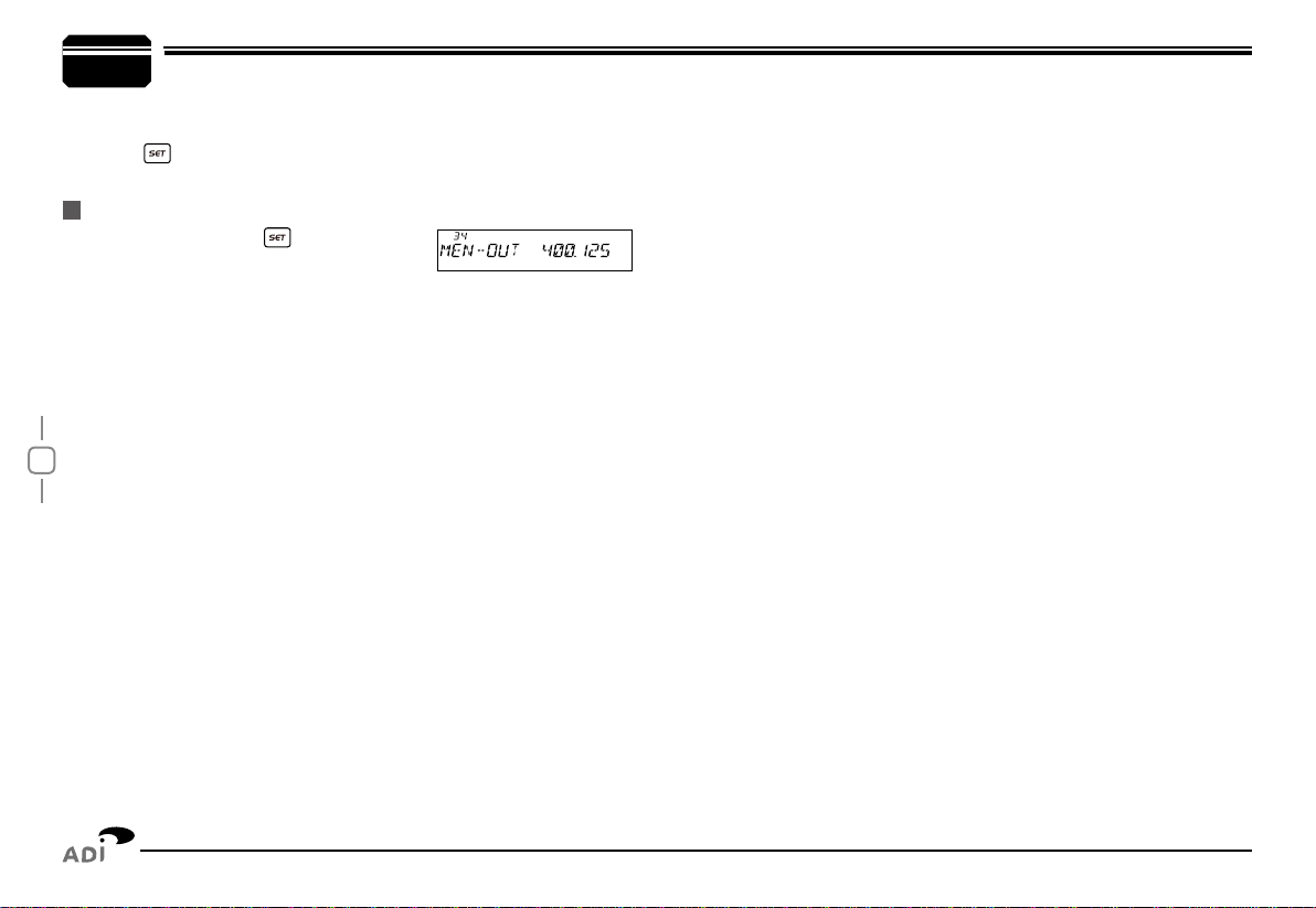
In standby, hold
1. key until the
transceiver prompt DU, and channel
number ashes.
Turn selector knob to choose channel number for delete. (If the
2.
storage has data, the LCD will display the frequency, otherwise will
display"----------")
Hold Main band volume knob, until the transceiver emit DU DU
3.
prompt and LCD displays MEN-OUT, the channel delete completed.
chAnnel delete
7
storage has data , the LCD will display the frequency, otherwise will
display"----------")
Press
4. key, the LCD displays MEN-IN, channel copy completed.
6

16
General Setting
Once APO is activated, the transceiver will be automatically switched
off when the pre-set timer running out.
Press
1. key to enter function menu.
Turn the Main band selector knob to
2.
choose No. 01 menu. the LCD displays "APO"
Press the Main band selector knob to enter function setup.
3.
Switch the Main band selector knob to
4.
choose wanted value.Available values:
0.5-12Hours, OFF
Press the Main band selector knob or
5. key to store value and
back to function menu.
Press key or hold selector knob for over 0.5 second to store setup
and exit.
Only in frequency (VFO) mode, this function is valid. Turn selector knob
to select frequency or frequency scanning which is restricted by frequency
step size.
Press
1. key to enter function menu.
Turn the Main band selector knob to
2.
choose No. 03 menu. the LCD displays "STEP"
Press the Main band selector knob to enter function setup.
3.
Switch the Main band selector knob to choose wanted value.
4.
Available Values: 2.5K, 5K, 6.25K, 10K,
12.5K, 15K, 20K, 25K, 30K,50K.
Press the Main band selector knob or
5. key to store value and
back to function menu.
Press key or hold selector knob for over 0.5 second to store setup
and exit.
When this function is on, the transceiver will automatically transmitting
with RX frequency ± offset frequency. The operation as following:
Press
1. key to enter function menu.
Apo (AutoMAtic poweR oFF)
FRequencY chAnnel Step Setup
AutoMAtic oFFSet
Turn the Main band selector knob to choose No. 02 menu. the LCD
2.
displays "ARS"
Press the Main band selector knob to
3.
enter function setup
Switch the Main band selector knob to choose wanted value.
4.
ON: Auto Offset function is turned on.
OFF Auto Offset function is turned off.
Press the Main band selector knob or
5.
key to store value and back to function menu.
Press key or hold selector knob for over 0.5 second to store setup
and exit.
When the Automatic offset is ON, the offset for 136-174Mhz is default on
0.6Mhz, and for 400-490 is default on 5Mhz.
7
NOTE
Basic operation steps for Function menu
1. Press key to enter function menu.
2. Turn the Main band selector knob to choose wanted function.
3. Press the Main band selector knob to enter function setup.
4. Switch the Main band selector knob to choose wanted value.
5. Press the Main band selector knob to store value and back to
function menu. Press key or hold selector knob for over 0.5
second to store setup and exit.
17
7General Setting
In VFO mode, when this function is on, the scanning or input of
frequency will restricted within the current VFO frequency band.
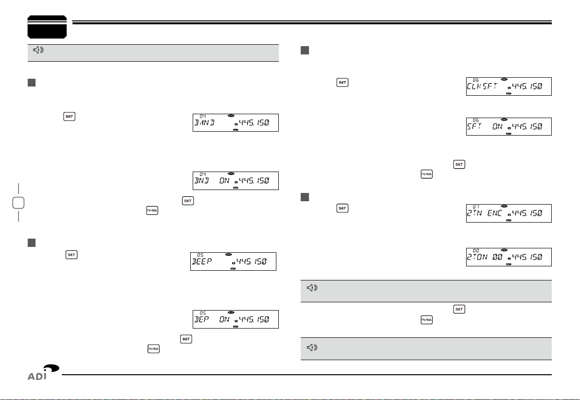
Press
1. key to enter function menu.
Turn the Main band selector knob to
2.
choose No. 04 menu. the LCD displays "BAND"
Press the Main band selector knob to enter function setup.
3.
Switch the Main band selector knob to choose wanted value.
4.
ON: Turn on VFO band lockout function
OFF: Turn off VFO band lockout function
Press the Main band selector knob or
5. key to store value and
back to function menu. Press key or hold selector knob for over
0.5 second to store setup and exit.
Press
1. key to enter function menu.
Turn the Main band selector knob to
2.
choose No. 05 menu. the LCD displays "BEEP"
Press the Main band selector knob to enter function setup.
3.
Switch the Main band selector knob to choose wanted value.
4.
ON: Turn on Beep function.
OFF: Turn off Beep function
Press the Main band selector knob or
5. key to store value and
back to function menu. Press key or hold selector knob for over
0.5 second to store setup and exit.
When any harmonic or image frequency in the CPU clock disturbs the
working frequency, turn on this function will cut the disturbing
Press
1. key to enter function menu.
Turn the Main band selector knob to
2.
choose No. 06 menu. the LCD displays "CLK.SFT"
Press the Main band selector knob to enter function setup.
3.
Switch the Main band selector knob to
4.
choose wanted value.
ON: Turn on CPU Clock frequency Change
OFF: Turn off CPU Clock frequency Change
Press the Main band selector knob or
5. key to store value and
back to function menu. Press key or hold selector knob for over
0.5 second to store setup and exit.
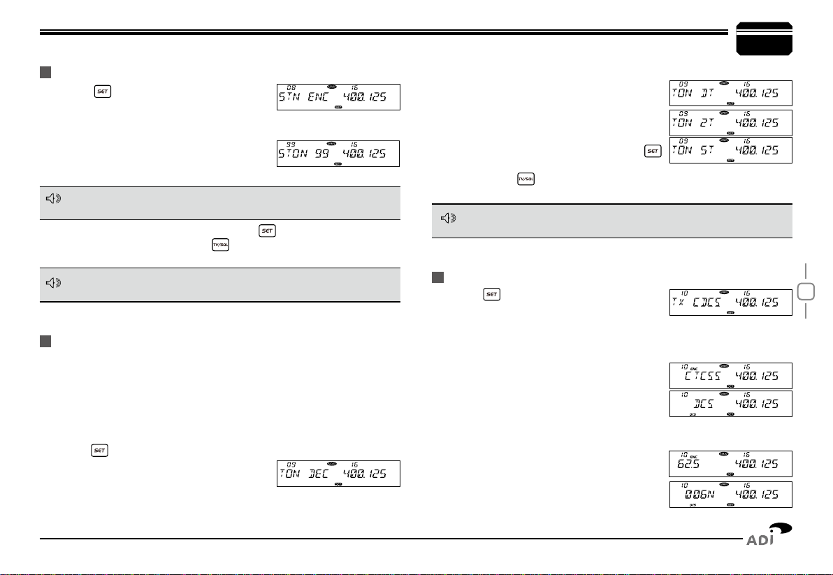
Press
1. key to enter function menu.
Turn the Main band selector knob to
2.
choose No. 07 menu. the LCD displays "2TN ENC"
Press the Main band selector knob to enter function setup.
3.
Switch the Main band selector knob to
4.
choose wanted value.
Available Values: 0-23, total 24 groups.
VFo bAnd lockout
beep Function
cpu clock FRequencY chAnGe
2tone encode Select
This function is auto-hidden in channel mode
if the 2TONE encode are programmed with name, the LCD will display
corresponding name.
After choose the 2TONE encode group. Press PTT will transmit selected
code.
Press the Main band selector knob or
5. key to store value and
back to function menu. Press key or hold selector knob for over
0.5 second to store setup and exit.
NOTE
NOTE
NOTE
18
General Setting
Press
1. key to enter function menu.
Turn the Main band selector knob to
2.
choose No. 08 menu. the LCD displays "5TN ENC"
Press the Main band selector knob to enter function setup.
3.
Switch the Main band selector knob to
4.
choose wanted value.
Available Values: 0-99, total 100 groups.
This transceiver has 3 optional signaling: DTMF/5Tone/2Tone,those
signaling function similar to CTCSS/DCS signaling. When the receiver
adds an optional signaling, the caller shall transmit matching signaling.
DTMF and 5Tone signaling can be applied for other advanced features
such as ANI, PTT ID, group call, select call, remotely stun, remotely kill
waken…etc
Press
1. key to enter function menu.
Turn the Main band selector knob to
2.
choose No. 09 menu. the LCD displays
"TON DEC"
Press the Main band selector knob to enter function setup.
3.
Press
1. key to enter function menu.
Switch the Main band selector knob to
2.
choose No 10 menu, the LCD displays "TX CDCS"
Press the Main band selector knob to enter function setup.
3.
Switch the Main band selector knob to choose wanted value
4.
OFF: Turn off CTCSS/DCS encode.
CTCSS: Choose CTCSS encode.
DCS: Choose DCS encode.
Press the Main band selector knob to enter the menu.
5.
Switch the Main band selector knob to choose wanted CTCSS, DCS
6.
code.
CTCSS: 62.5-254.1HZ, and one self-
dene group, total 52 groups
DCS: 000N-777I, total 1024 groups
5tone encode Select
Add optionAl SiGnAlinG
ctcSS/dcS encode Setup
Press the Main band selector knob or
5. key to store value and
back to function menu. Press key or hold selector knob for over
0.5 second to store setup and exit.
if the 5TONE encode are programmed with name, the LCD will display
corresponding name.
After choose the 5TONE encode group. Press PTT will transmit selected
code.
The working of optional signaling shall be work associated with the squelch
mode setup. (Refer to Squelch Mode setup in page 20)
Switch the Main band selector knob to choose wanted value
4.
DT: means DTMF signaling is added.
2T: means DTMF signaling is added.
5T: means DTMF signaling is added.
OFF: Turn off optional signaling
Press the Main band selector knob or
5.
key to store value and back to function
menu.Press key or hold selector knob for over 0.5 second to
store setup and exit.
7
NOTE
NOTE
NOTE
19
General Setting
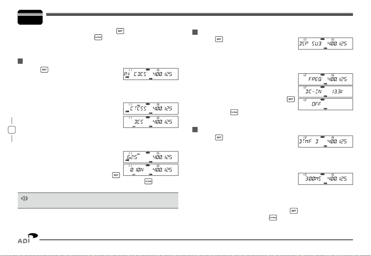
Press
1. key to enter function menu.
Switch the Main band selector knob to
2.
choose No 11 menu, the LCD displays "RX CDCS"
Press the Main band selector knob to enter function setup
3.
Switch the Main band selector knob to choose wanted value
4.
OFF: Turn off CTCSS/DCS decode.
CTCSS: Choose CTCSS decode.
DCS: Choose DCS decode.
Press the Main band selector knob to enter the menu.
5.
Switch the Main band selector knob to choose wanted CTCSS, DCS
6.
code.
CTCSS: 62.5-254.1HZ, and one self-
dened group, total 52 groups
DCS: 000N-777I, total 1024 groups
Press the Main band selector knob or
7.
key to store value and back to function menu. Press key or hold
selector knob for over 0.5 second to store setup and exit.
Press
1. key to enter function menu.
Turn the Main band selector knob to
2.
choose No. 12 menu. the LCD displays "DSP SUB"
Press the Main band selector knob to enter function setup
3.
Switch the Main band selector knob to choose wanted value.
4.
FREQ: display sub band frequency,
DC-IN: display sub band voltage.
OFF: turn off display for sub Band
Press the Main band selector knob or
5.
key to store value and back to function
menu. Press key or hold selector knob
for over 0.5 second to store setup and exit.
Press
1. key to enter function menu.
Turn the Main band selector knob to
2.
choose No. 13 menu. the LCD displays "DTMF D"
Press the Main band selector knob to enter function setup
3.
Switch the Main band selector knob to choose wanted value.
4.
100MS: The Pre-Loading time is 100MS
300MS: The Pre-Loading time is 300MS
500MS: The Pre-Loading time is 500MS
800MS: The Pre-Loading time is 800MS
1000MS: The Pre-Loading time is 1000MS
Press the M
5. ain band selector knob or key to store value and
back to function menu. Press key or hold selector knob for over
0.5 second to store setup and exit.
ctcSS/dcS decode Setup
Sub bAnd diSplAY Setup
dtMF encode pRe-loAdinG tiMe
The working of CTCSS/DCS decode shall be work associated with the
squelch mode setup. (Refer to Squelch Mode setup in page 20)
Press the Main band selector knob or
7. key to store value and
back to function menu. Press key or hold selector knob for over
0.5 second to store setup and exit.
7
NOTE
Table of contents
Other ADI Radio manuals


