PNI escort HP 8001 ASQ User manual

Manual de utilizare
Statie radio CB
PNI Escort HP 8001 ASQ

2
Inainte sa conectati sau sa utilizati acest produs, va rugam sa cititi cu
atentie aceste instructiuni de utilizare si pastrati acest manual pentru o utilizare
ulterioara.
CUPRINS
1. CARACTERISTICI PRINCIPALE.......................................................................................................................3
2. SPECIFICATII TEHNICE....................................................................................................................................3
3. DESCRIERE PRODUS.......................................................................................................................................4
4. INSTALARE........................................................................................................................................................6
5. SFATURI UTILE .................................................................................................................................................7
6. FRECVENTELE SI PUTERILE LEGALE IN EUROPA SUNT:..........................................................................8
ATENTIE:
PENTRU A PREVENI RISCUL DE INCENDIU NU UTILIZATI DECAT O SURSA
DE ALIMENTARE CORESPUNZATOARE.
NU EXISTA COMPONENTE CARE POT FI REPARATE DE UTILIZATOR.
PENTRU REPARATII ADRESATI-VA UNUI SERVICE AUTORIZAT.
Manual de utilizare
Camera securitate CCTV
model PNI 68HR3CA

3
1. Caracteristici principale
40 de canale FM/AM
Comutator selectare mod FM/AM (AM functioneaza doar prin schimbarea
normei)
Comutator selectare canal de urgenta 9/19
Butoane selectare canal UP/DOWN
LED-uri indicatoare nivel semnal
Indicator numar canal din 2 cifre
Potentiometru volum si pornire/oprire statie
Indicator LED verde pentru ASQ
Microfon cu butoane de selectare canal (sus/jos) si activare ASQ
Mufa microfon cu 6 pini pe panoul frontal
Mufa pentru difuzor extern
Squelch manual
Squelch automat ajustabil
Conector antena
2. Specificatii tehnice
Canale
40 AM/FM
Banda de frecventa
26.965 –27.405 MHz
Control frecventa
P.L.L.
Temperatura de functionare
-10° - +55°C
Alimentare
13.8Vdc ±15%
Dimensiuni
115 x 36 x 152 mm
Greutate
0.8 kg
Receptor
Frecventa intermediara
1° 10.7 MHz / 2° 450 KHz
Sensibilitate
-120dBm / 12dB SINAD (FM)
-107dBm / 12dB SINAD (AM)
Iesire audio
@10% THD 2.5W la 8 ohm
Distorsiune audio
<8% at 1 KHz
Rejectie imagine
65 dB
Canal adiacent
85 dB
Consum curent
200 mA in stand-by

4
Emitator
Putere maxima RF
4W FM la 13.8Vdc
Modulatie
85% la 90% (AM)
3KHz ±0.2 KHz (FM)
Impredanta antena
50 Ohm
Consum curent
2 A
3. Descriere produs
1. Conector 6 pini pentru microfon
2. Buton crestere numar canal
3. Buton scadere numar canal
4. Potentiometru ajustare squelch –squelch-ul face statia mai silentioasa prin
eliminarea zgomotelor de pe fundal. Rotiti potentiometrul in sensul acelor
de ceasornic pentru a reduce zgomotele, sau in sensul invers acelor de
ceasornic daca doriti sa auziti si cele mai slabe semnale
5. Potentiometru ASQ –pentru a creste nivelul de ASQ rotiti potentiometrul in
sensul acelor de ceasornic, in acest caz se reduce zgomotul de fundal, dar
si nivelul semnalului receptionat. RECOMANDARE: porniti statia cu ASQ
rotit la stanga.
6. Potentiometru pornire/oprire statie si ajustare volum –rotiti in sensul acelor
de ceasornic pentru a porni statia si a mari volumul. Daca nu se
receptioneaza nici un semnal va sugeram sa ajustati squelch-ul (prin rotirea
potentiometrului SQ in sens invers acelor de ceasornic) si apoi volumul la
un nivel confortabil. Cand este pornita din potentiometrul de volum, statia
va memora ultimul canal utilizat.
7. Buton selectare mod AM/FM. (În AM functioneaza doar prin schimbarea

5
normei).
8. Comutator selectare canal de urgenta 9/19 sau mod normal de functionare
CH. In modul CH se pot selecta toate celelalte canale 1~40. In Romania
canalul utilizat este 22.
9. LED indicator TX/ASQ. In timpul emisiei LED-ul va fi rosu, iar cand functia
ASQ este activata LED-ul va fi verde.
10. Indicator nivel semnal –indicator cu 4 bare pentru a monitoriza
puterea semnalelor receptionate/emise
11. Ecran LED –afiseaza numarul canalului
A. Mufe pentru casca si microfon
12. Conector antena
13. Cablu de alimentare 13.8VDC
14. Mufa pentru difuzor extern
15. Buton PTT –apasati pentru a
emite
16. Buton marire numar canal
17. Buton activare/dezactivare functie
ASQ
18. Buton micsorare numar canal
19. Mufa 6 pini pentru conectarea
microfonului in statie

6
4. Instalare
Inainte de a instala unitatea centrala in masina, verificati si alegeti cea mai
convenabila pozitie, pentru a avea acces usor la statie si pentru a o putea folosi
fara a va deranja de la condus. Utilizati suportul si accesoriile din pachet pentru a
instala statia. Suruburile suportului trebuie stranse bine pentru a evita vibratia
statiei in timpul mersului. Suportul de montaj poate fi pozitionat deasupra sau sub
statie, iar aceasta poate fi inclinata in functie de modul de instalare (sub bord sau
sub tavanul cabinei de camion).
ATENTIE: Asigurati-va ca tensiunea la care alimentati statia este cea indicata de
fabricant.
Instalarea unitatii centrale: inainte de a alimenta statia, asigurati-va ca
butonul de pornire este maxim la stanga. Cablul de alimentare al statiei include o
siguranta de protectie pe firul rosu. Conectati cablul de alimentare al statiei la
sistemul electric al autovehiculului cu atentie sporita la polaritate, chiar daca
statia are protectia la inversarea de polaritate. Conectati firul rosu la borna
pozitiva (+) si firul negru la borna negativa (-) a sistemului electric a
autovehiculului. Verificati corectitudinea conexiunilor efectuate, pentru a preveni
deconectarea acestora sau un eventual scurtcircuit.
ATENTIE: In cazul arderii sigurantei nu o inlocuiti cu una de valoare mai mare.
Cea din fabrica are 2A.
Instalarea antenei: pentru utilizarea statiei aveti nevoie de o antena
specifica ce functioneaza in frecventa 27.225MHz. Instalarea antenei trebuie
efectuata de un tehnician specializat. Pozitionati antena corespunzator pe

7
autovehicul. Inainte de a conecta antena la statie este necesara verificarea
antenei cu un aparat specializat, altfel se poate defecta circuitul de emisie al
statiei. De obicei antena trebuie pozitionata pe partea cea mai inalta a
autovehiculului, fara a fi obstructionata de obstacole si cat mai departe de orice
sursa electrica sau zgomot electromagnetic. Cablul coaxial al antenei nu trebuie
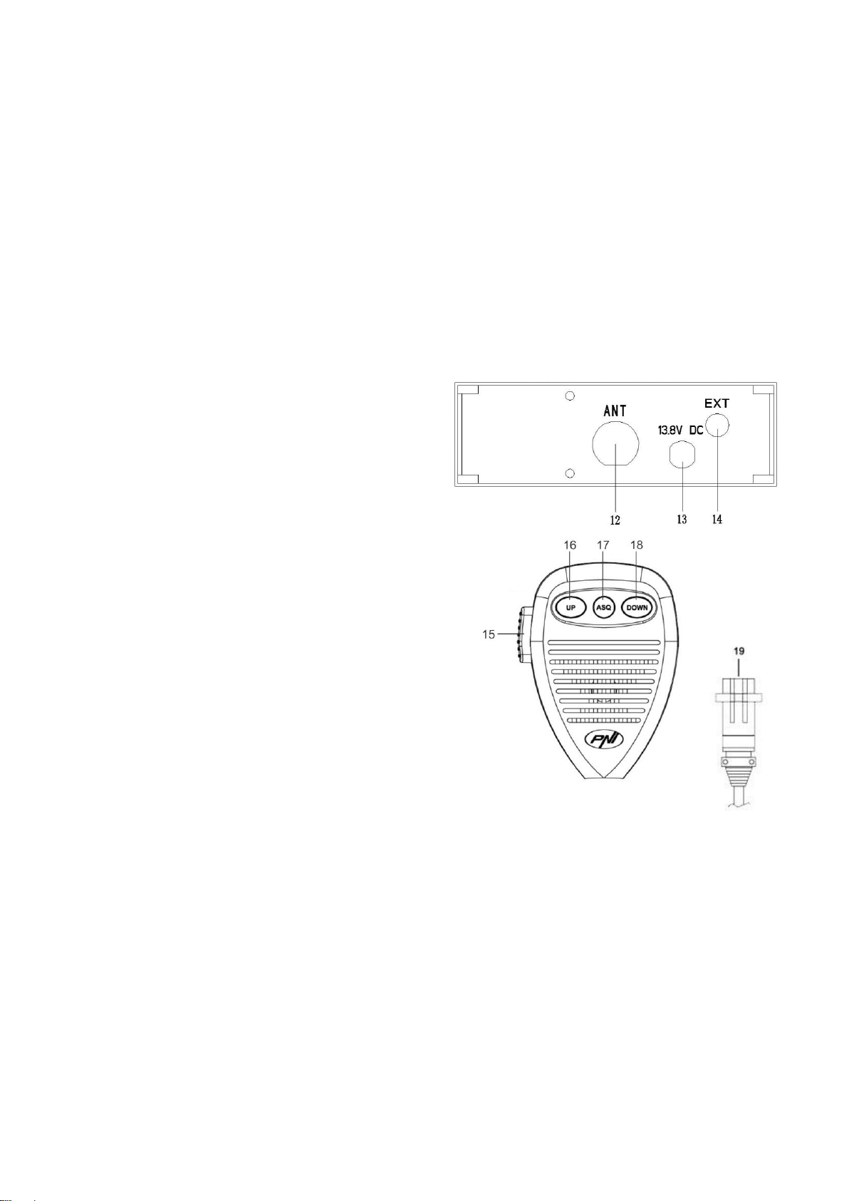
sa fie intrerupt sau presat. Conectati mufa din capatul cablului coaxial al antenei
la mufa de antena din spatele statiei.
Verificarea functionarii statiei: odata instalata statia si alimentata de la
sistemul electric al autovehiculului, procedati in felul urmator pentru a verifica
functionarea acesteia:
Verificati daca alimentarea este conectata corect
Verificati conexiunea antenei la statie
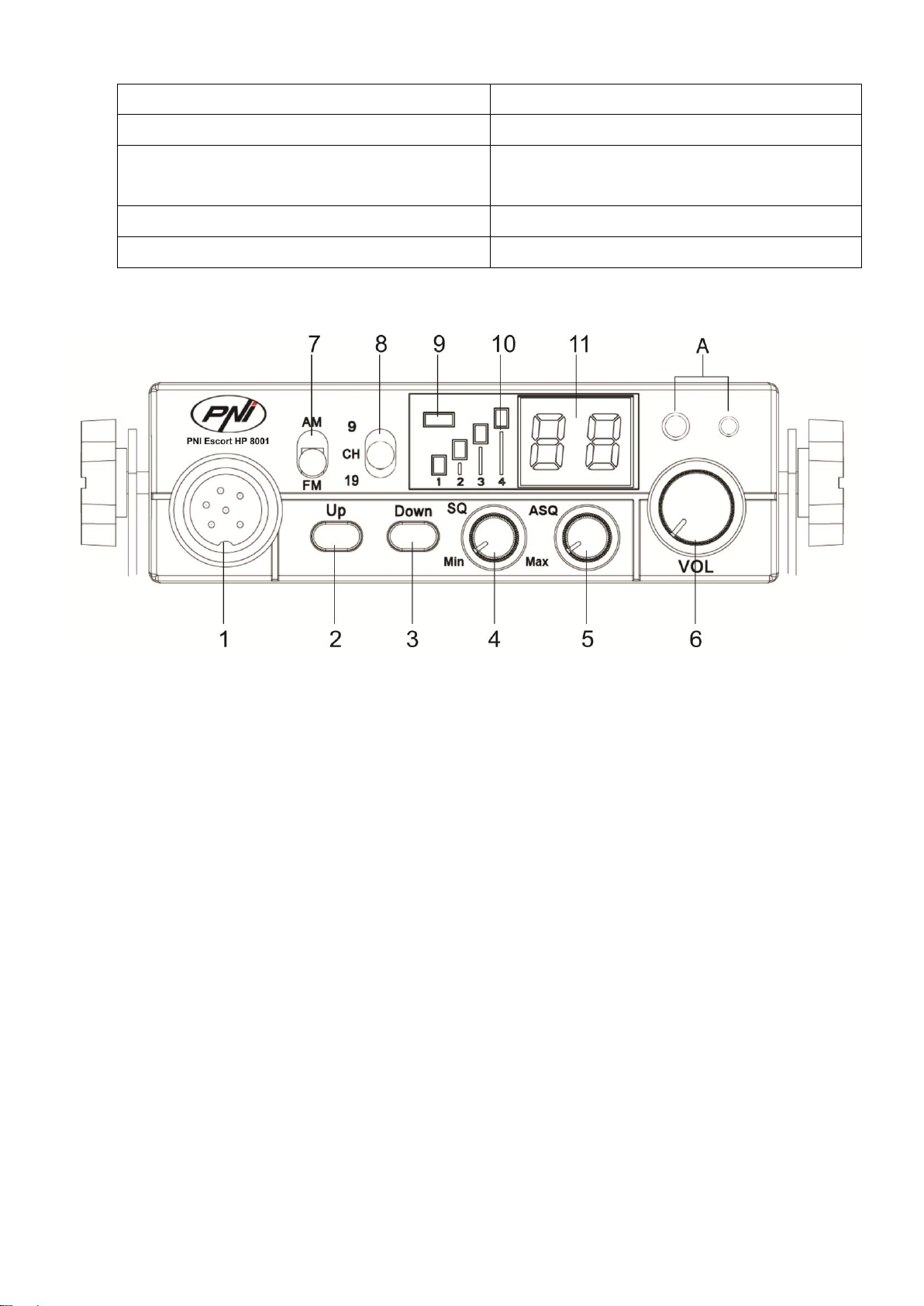
Conectati microfonul la mufa de pe panoul frontal al statiei
Porniti statia prin rotirea potentiometrului de volum in sensul acelor de
ceasornic si ajustati volumul la nivelul dorit
Selectati canalul dorit prin intermediul tastelor UP/DOWN de pe
panoul frontal al statiei sau de pe microfon; in Romania se utilizeaza
canalul 22
Actionati butonul SQ in zona limita in care dispare zgomotul de
fundal. Daca modul ASQ este activat (de pe microfon) butonul SQ nu
mai functioneaza
Apasati butonul PTT de pe microfon pentru a emite, si eliberati-l
pentru a receptiona
Verificati nivelul semnalului receptionat prin intermediul barelor de
semnal de pe panoul frontal al statiei
Porniti functia ASQ de pe microfon si reglati nivelul acestuia din
butonul ASQ de pe panoul frontal al statiei
5. Sfaturi utile
Nu inversati polaritatea de alimentare a statiei
Nu inlocuiti siguranta arsa cu una de valoare mai mare; Cea din
fabrica are 2A.
Nu emiteti fara antena sau cu o antena defecta sau necalibrata,
pentru a evita arderea finalului de emisie

8
Reglati SQ si ASQ la limita disparitiei zgomotului de fundal. Prin
rotirea butonul SQ in sensul acelor de ceasornic prea mult, nu veti
receptiona decat semnalele puternice (cele emise din apropiere)
6. Frecventele si puterile legale in Europa sunt:
Italia 40CH AM/FM 4 watt
Italia 34CH AM/FM 4 watt
Germania 80 CH FM 4watt/ 12 CH AM 1watt
Germania 40 CH FM 4watt/ 12 CH AM 1watt
Europa 40 CH FM 4 watt/ 40 CH AM 1watt
Romania CEPT 40 CH FM 4watt
Spania 40 CH AM/FM 4watt
Franta 40 CH FM 4watt/ 40 CH AM 1watt
Anglia 40 CH FM 4watt frecvente engleze + EC 40 CH FM 4 watt frecvente
CEPT
ATENŢIE! Acest produs este destinat sa fie utilizat in Romania si functioneaza
pe norma EC Europa 40 CH FM 4 watt. Pentru a functiona in AM va trebui sa
schimbati norma din EC in d.
ATENŢIE! In Romania este permis doar 1 watt pentru modulatie AM!
Specificatiile se pot modifica fara preaviz!

37
USER MANUAL
CB RADIO
PNI Escort HP 8001 ASQ

Before connecting and using this product, please read carrefully these instruction
manual and keep it for later use.
CONTENTS
1. Main Features............................................................................................................. 4
2. Technical Indicators .................................................................................................... 4
3. Product description ..................................................................................................... 5
4. Installation ................................................................................................................... 7
5. Usefull tips .................................................................................................................. 8
6. Legal frequencies and transmiting powers in Europe: ............................................... 8
ATENTION:
TO PREVENT FIRE HAZZARDS USE PROPER POWER SOURCE.
THERE ARE NO COMPONENTS THAT CAN BE REPAIRED BY THE USER.
FOR REPAIRS PLEASE REFER TO A N AUTHORIZED SERVICE.

1. Main Features
• 40 AM/FM channels
• P/E Frequency band selectable (Russia and EU band switchable )
• Mode AM/FM switch
• RSSI indication (4 PCS LED indications)
• 2 Digit channel indicator
• RF gain control
• Volume with power ON/OFF control
• TX/RX AS Q LED indicator
• Up /Down microphone
• Front microphone plug
• Jack for external speaker
• Manual Squelch
• ANT Connector
2. Technical Indicators
Channels
40 AM/FM
Frequency range
26.965 – 27.405 MHz
Frequency control
P.L.L.
Operating temperature
-10° - +55°C
DC input voltage
13.8Vdc ±15%
Size
115 x 36 x 152 mm
Weight
0.8 kg
Receiver
IF
1° 10.7 MHz / 2° 450 KHz
Sensitivity
-120dBm / 12dB SINAD (FM)
-107dBm / 12dB SINAD (AM)
Audio output
@10% THD 2.5W la 8 ohm
Audio distortion
<8% at 1 KHz
Image rejection
65 dB
Adjacent channel
85 dB
Current drain
200 mA in stand-by
Transmitter

Maximum RF power
4W FM la 13.8Vdc
Modulation
85% la 90% (AM)
3KHz ±0.2 KHz (FM)
ANT impedance
50 Ohm
Current drain
2 A
3. Product description
1. MICROPHONE connector : Connect the supplied electric condenser microphone
to this connector, and then lock it via the ring nut.
2. UP KEY : Press this key and channel NO. runs up.
3. DOWN KEY : Press this key channel NO. runs down.
4. SQ knob : The SQUELCH control allows to silent the receiver by cutting the
background noise. Turn the SQUELCH knob anticlockwise until the background noise
is cut. Rotate the SQUELCH knob clockwise (SQUELCH ON) to listen to the weakest
signals.
5. ASQ knob : to increase the ASQ level rotate the knob clockwise, in this case the
background noise is reduced but also the received signal. Recommended: turn on the
radio CB with the ASQ knob on the left.
6. OFF/VOL : This knob controls the radio ON and OFF as well as adjusts the volume.
If no signals are being received on the operating channel, it is suggested to turn on the
SQUELCH and adjust the volume to the desired level while listening to the background
noise. When it is turned on by operating the Volume knob,the radio will remember the
channel, frequency, AM or FM used last time.

7. AM/FM mode selector: This switch allows selecting the modulation mode AM/ FM.
8. Emergency channel or function mode selector: with this button you can select one
of the emergency channels 9/19 or the normal CH functioning mode. In the CH mode
you can select the number of the channel you want to use. In Romania they use channel
no22.
9. TX/ASQ LED: The indicator is bicolor light as red and green color. When TX
is red color, when ASQ on is green light.
10. RX Signal Meter: 4-bar RX signal Meter to monitor the strength of the received
signals.
11. DISPLAY: The digital LED display shows the channel.
A. Earphone and Microphone Jack
12. ANTENNA CONNECTOR
13. 13.8 VDC POWER CORD
14. EXT (External Speaker) Jack
15. PTT (Push-to-talk) key: Push the button to talk then release to receiving mode.
16. UP key 0f the microphone: This switch
allows increasing a channel number.
17. ASQ: Press this button, TX a nd ASQ
on the LED wo uld be green light, shows
ASQ turn on.
18. DN key of the microphone: This switch
allows decreasing a channel number.
19. MICROPHONE plug: 6-pole
microphone plug with locking ring nut, to be
connected to socket (1) located on the front
side of the radio.

4. Installation
Before installing the main unit in the vehicle, please check and select the most
convenient position, in order that the radio will be easy to reach and comfortable to
operate without disturbing or interfering driving. Use the supplied bracket and hardware
to install the radio. The bracket screws must be well tightened to avoid looseness as the
vehicle vibrates. The car mounting bracket can be installed over or below the radio and
the radio may be inclined as desired according to the specific type of installation (under
dashboard or track cabin roof installation).
Installation of the Main Unit
Before connecting the radio to the vehicle electric system, please make sure the
radio is powered off with the OFF/VOL (6) knob completely turned anticlockwise at
OFF position. The DC power cable of the radio includes a fuse holder with fuse located
on the red positive (+) wire. Please connect the DC power cable to the vehicle electric
system with special attention to correct polarity, even if the radio is protected against
polarity inversion. Connect the red wire to the positive (+) pole and the black wire to
the negative (-) pole of the vehicle electric system. Please make sure that the wires and
terminals are firmly connected, to prevent cables from disconnecting or causing short
circuits.
Installation of the Antenna
A specific mobile antenna adjusted for 27 MHz frequency range must be used. The
antenna installation must be done by a qualified technician or service center. Please
install the antenna carefully on the vehicle with proper connection to ground. Before

connecting the antenna to the radio, it is necessary to check the correct operation of the
antenna with low standing wave ratio (S.W.R.) via adequate instruments. If not, the
transmitter circuit of the radio could be damaged. The antenna usually must be installed
on the highest part of the vehicle, free from obstacles and as far away as possible from
any source of electric or electromagnetic noise. The RF antenna coaxial cable must not
be damaged or pressed on its way between antenna and the radio. The correct operation
of the antenna and the low standing wave ratio (S.W.R.) must be checked periodically.
Connect the RF antenna coaxial cable to the antenna connector (15), located on the rear
side of the radio.
Checking Operation of the Radio
Once radio has been connected to the vehicle electric system and to the antenna, the
correct operation of the system should be checked. Please proceed as following:
1) Check that the power cable is correctly connected.
2) Check that the RF antenna coaxial cable is properly connected.
3) Connect the microphone to the connector (1) that is on the front side of the radio.
4) Rotate the SQUELCH (4) knob anticlockwise.
5) Turn radio on by the OFF/VOL (6) knob and adjust volume to the desired level.
6) Select the desired channel with the up/down key on the front side of the radio.
7) Rotate the SQUELCH (4) knob clockwise to cut the background noise.
8) Press the PTT key to transmit and release it to receive.
9) Check the level of the received and transmitted signals on the 4 bar RX signal Meter
and TX LED. The transceiver will work correctly.
5. Useful tips
• Do not invert power polarity
• Do not replace the fuse with a bigger one. The default is 2A.
• Do not transmit without an antenna connected, you risc damaging the
device.
• Set the SQ and ASQ at the limit of the background noise.
6. Legal frequencies and transmitting powers in Europe:
Italy 40CH AM/FM 4 watt
Italy 34CH AM/FM 4 watt
Germany 80 CH FM 4watt/ 12 CH AM 1watt
Germany 40 CH FM 4watt/ 12 CH AM 1watt

Europe 40 CH FM 4 watt/ 40 CH AM 1watt
Romania CEPT 40 CH FM 4watt
Spain 40 CH AM/FM 4watt
France 40 CH FM 4watt/ 40 CH AM 1watt
GB 40 CH FM 4watt English frequencies + EC 40 CH FM 4 watt CEPT
frequencies
Specifications subject to change without notice!

Felhaszn
álói
kézikönyv
Rádió‐adó‐vevő
PNI Escort HP 8001 AS
Q

2
A készülék első bekapcsolása vagy használata előtt, kérjük olvassa el figyelmesen
ezeket az utasításokat és tartsa meg ezt a kézikönyvet a későbbi felhasználás céljából.
A KÉSZÜLÉK NEM TARTALMAZZA A FELHASZNÁLÓ ÁLTAL JAVÍTHATÓ
EGYSÉGEKET, ÍGY MINDEN SZERVÍZFELADAT ELVÉGZÉSÉHEZ KÉRJE
HIVATALOS SZERVÍZ SEGÍTSÉGÉT.
FIGYELEM:
TŰZVESZÉLY MEGAKADÁLYOZÁSA ÉRDEKÉBEN, CSAK MEGFELELŐ
ÁRAMFORRÁST HASZNÁLJON.
TARTALOM
1. FŐBB
JELLEMZŐK………………
.................................................................................................................................3
2. MŰSZAKI
ADATOK……..
...............................................................................................................................................
3
3.
TERMÉKLEÍRÁS.........
............................................................................................................................. ........................
4
4.
TELEPÍTÉS... ......................................................................................................................................................................
5
5.
TANÁCSOK.........
...................................................................
............................................................................................
7

3
1. Főbb jellemzők
•
40 csatorna
•
Üzemmod kapcsolóval AM/FM (AM-be csak akkor működik ha változik a norma)
•
Sűrgösségi csatorna kapcsoló 9/19
•
Csatornaváltó gombok UP/DOWN
•
LED kijelző
•
2 kijelzős csatornaszám
•
Potenciaméter hangerő és Start/Stop adó-vevő
•
Zöld LED ASQ kijelző
•
Mikrofon gombok a csatorna kiválasztásához (le/fel) és az ASQ aktiválásához
•
6 pólusú mikrofon csatlakozó az előlapon
•
Aljzat a külső hangszorónak
•
Kézi zajszűrés
•
Beállítható autómatikus zajzár
•
Antenna csatlakozó
2. Műszaki adatok
Csatorna
40 AM/FM
Sávszélesség
26.965 – 27.405 MHz
Frekvenciavezérlés
P.L.L.
Üzemi hőmérséklet
-10° - +55°C
Táplálás
13.8Vdc ±15%
Méretek
115 x 36 x 152 mm
Súly
0.8 kg
Vevőegység
Köztes frekvencia
1° 10.7 MHz / 2° 450 KHz
Érzékenység
-120dBm / 12dB SINAD (FM)
-107dBm / 12dB SINAD (AM)
Hangkimenet
@10% THD 2.5W la 8 ohm
Hangtorzítás
<8% at 1 KHz
Képfrekvencia elnyomás
65 dB
Szomszédos csatorna
85 dB
Fogyasztás
200 mA in stand-by

4
Adóegység
Maximális teljesítmény
4W FM la 13.8Vdc
Moduláció
85% la 90% (AM)
3KHz ±0.2 KHz (FM)
Ellenállás antenna
50 Ohm
Fogyasztás
2 A
3. Termék leírás
‐
1. 6 pólusú mikrofon csatlakozó.
2. Csatornaszám növelő gomb.
3. Csatornaszám csökkentő gomb.
4. Potenciaméterrel rendelkező zajzár – a zajzár csendesíti az adó-vevő háttérzaját.
Forgassa a potenciamétert az óramutató járásával megegyező irányba, hogy
csökkentse a zajt, vagy azzal ellentétes irányba, ha azt szeretné, hogy a háttérzaj
meg gyengébb legyen.
5. ASQ potenciaméter – az ASQ szintjének növelése érdekében a potenciamétert
forgassa az óramutató járásával megegyező irányba, ebben az esetben csökkenti a
hátterzajt vagy a kapott jelet. AJÁNLÁS: az ASQ állomás bekapcsolásához
forgassa balra.
6. Ki-/bekapcsó és hangerő szabályozó potenciaméter – forgassa az óramutató
járásával megegyező irányba a kekapcsoláshoz és a hangerő növeléséhez. Ha nincs
jel az a javaslat, hogy segít a zajzár (SQ – forgassa az óramutató járásával ellentétes
irányba), majd a hangerőt egy kényelmes szintre. Amikor bekapcsolja és állítja a
hangerőt, a készülék emlékezik az utolsó használt csatornára.
7. AM/FM kiválasztó gomb. (AM-be csak akkor működik ha változik a norma).
Table of contents
Languages:
Other PNI Radio manuals

PNI
PNI ESCORT HP 8900 User manual

PNI
PNI Escort HP 9700 USB User manual

PNI
PNI R40 Pro User manual

PNI
PNI Escort HP 9001 ASQ User manual

PNI
PNI ESCORT HP 62 User manual

PNI
PNI Escort HP 8001L ASQ User manual

PNI
PNI Escort HP 5500 User manual

PNI
PNI PMR R45 PRO User manual

PNI
PNI ESCORT HP 9500 User manual

PNI
PNI R40 Pro User manual

PNI
PNI Escort HP 9001 PRO User manual

PNI
PNI Escort HP 8000L User manual

PNI
PNI ESCORT HP 55 User manual

PNI
PNI Escort HP 8024 ASQ 12V-24V User manual

PNI
PNI ESCORT HP 9700 User manual

PNI
PNI ESCORT HP 72 User manual

PNI
PNI Escort HP 8000L User manual

PNI
PNI RD290 User manual

PNI
PNI PMR R30 User manual

PNI
PNI Escort HP 8500 User manual