ADI AF-16 User manual


Dear users,
We are grateful you choose ADI for your land
mobile radio applications. We believe this easy-
to-use transceiver will provide dependable and
reliable communication to personnel operation at
peak efficency.
ADI transceivers incorporate the latest advanced
technology. As a result, we feel strongly that you
will be pleased with the quality and features of
this product!
For you to understand the operation and mainte-
nance of this transceiver, please read carefully
the user’s manual.
This manual is applicable to the following models:
AF-16:VHF frequency modulation wireless transceiver.
AF-46:UHF frequency modulation wireless transceiver.

SAFETY INFORMATIONSAFETY INFORMATION
......................................................
1-21-2
UNPACKING AND CHECKING EQUIPMENTUNPACKING AND CHECKING EQUIPMENT
..............................
33
SUPPLIED ACCESSORIES SUPPLIED ACCESSORIES
................................................
33
PREPARATIONPREPARATION
....................................................................
4-64-6
CHARGING THE BATTERY PACK CHARGING THE BATTERY PACK
........................................
44
INSTALLING/REMOVING THE ANTENNA INSTALLING/REMOVING THE ANTENNA
..............................
55
INSTALLING/REMOVING THE LI-ION BATTERY PACK INSTALLING/REMOVING THE LI-ION BATTERY PACK
............
55
INSTALLING THE BELT CLIP INSTALLING THE BELT CLIP
..........................................
66
INSTALLING THE HAND STRAP INSTALLING THE HAND STRAP
........................................
66
INSTALLING THE OPTIOPNAL EARPHONE INSTALLING THE OPTIOPNAL EARPHONE
..........................
66
GETTING ACQUAINTEDGETTING ACQUAINTED
....................................................
7-127-12
ORIENTATION ORIENTATION
................................................
..............
77
KEYPAD OPERATION KEYPAD OPERATION
......................................................
99
LCD DISPLAY LCD DISPLAY
............................................................
1111
BASIC OPERATIONBASIC OPERATION
........................................................
13-1413-14
BASIC MODES BASIC MODES
..................................................
..........
1313
VFO MODE (FREQUENCY DISPLAY MODE) VFO MODE (FREQUENCY DISPLAY MODE)
..................
1313
MR NODE (MEMORY REACALL MODE) MR NODE (MEMORY REACALL MODE)
........................
1313
CH MODE (CHANNEL DISPLAY MODE) CH MODE (CHANNEL DISPLAY MODE)
........................
1313
SWITCH POWER ON/OFF SWITCH POWER ON/OFF
................................................
1313
ADJUST THE VOLUME ADJUST THE VOLUME
..................................................
1414
SELECT A FREQUENCY SELECT A FREQUENCY.........................14.........................14
SELECT AN OUTPUT POWER SELECT AN OUTPUT POWER
..........................................
1414
FUNCTION SETTING AND DESCRIPTIONFUNCTION SETTING AND DESCRIPTION
......................
15-2415-24
ADJUST SQUELCH (SQL) ADJUST SQUELCH (SQL)
..............................................
1515
BATTERY SAVER (SAVE) BATTERY SAVER (SAVE)
..............................................
1515
AUTOMATIC POWER OFF (APO) AUTOMATIC POWER OFF (APO)
......................................
1616
KEYPAD BEEPER (BEEP) KEYPAD BEEPER (BEEP)
..............................................
1616
KEYPAD LOCK (LOCK) KEYPAD LOCK (LOCK).........................16.........................16
RECEIVE WITH CTCSS/DCS RECEIVE WITH CTCSS/DCS
..........................................
1717
TRANSMIT WITH CTCSS/DCSTRANSMIT WITH CTCSS/DCS
..............................................
1818
CTCSS STANDARD FREQUENCY TABLE CTCSS STANDARD FREQUENCY TABLE
....................................
1919
DCS STANDARD SETS DCS STANDARD SETS
......................................................
1919
SETTING OFFSET DIRECTION AND OFFSET FREQUENCY (ASY) SETTING OFFSET DIRECTION AND OFFSET FREQUENCY (ASY)
......
2020
VOICE COMPANDER/SCRAMBLER (APS) VOICE COMPANDER/SCRAMBLER (APS)
..................................
2121
MEMORY CHANNEL SCAN LOCK/UNLOCK (SA/D) MEMORY CHANNEL SCAN LOCK/UNLOCK (SA/D)
........................
2121
FREQUENCY STEP SETTING FREQUENCY STEP SETTING
..........................................
2222
BROAD/NARROW BAND (W/N) BROAD/NARROW BAND (W/N)
........................................
2222
TIME OUT TIMER (TOT) TIME OUT TIMER (TOT)..............................................
2222
SCAN (SCAN) SCAN (SCAN)
............................................................
2323
SCAN METHOD SCAN METHOD......................................................
2323
SELECTING SCAN METHOD SELECTING SCAN METHOD......................................
2323
VFO SCAN VFO SCAN
.................................24.................................24
MEMORY CHANNEL SCAN MEMORY CHANNEL SCAN
........................24........................24
MEMORY CHANNELMEMORY CHANNEL
..........................................................
25-2725-27
STORING MEMORY CHANNEL STORING MEMORY CHANNEL
..........................................
2525
USING MEMORY CHANNEL USING MEMORY CHANNEL..............................................
2525
INITIALIZING MEMORY INITIALIZING MEMORY
........................26........................26
FULL RESET INITIALIZATION (MEMORY MODE) FULL RESET INITIALIZATION (MEMORY MODE)
........
2626
PARTIAL RESET INITIALIZATION (VFO MODE) PARTIAL RESET INITIALIZATION (VFO MODE)
........
2626
CHANNEL RESET INITIALIZATION (MR MODE) CHANNEL RESET INITIALIZATION (MR MODE)
..........
2727
USAGE AND MAINTENANCE INSTRUCTIONUSAGE AND MAINTENANCE INSTRUCTION
..........................
2828
CONTENT CONTENT
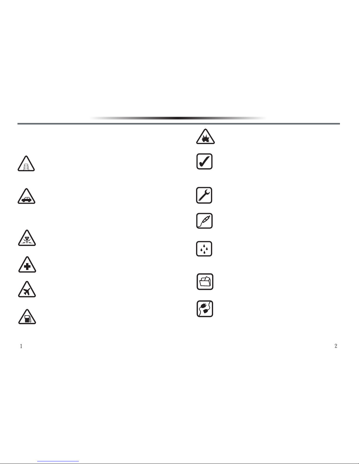
SWITCH OFF NEAR EXPLOSIVE PLACESSWITCH OFF NEAR EXPLOSIVE PLACES
Follow any restrictions. Do not use the trans-
ceiver in the explosive places.
USE SENSIBLY USE SENSIBLY
Use only in the normal position as explained in
the product documentation. Do not touch the
antenna unnecessarily.
QUALIFIED SERVICEQUALIFIED SERVICE
Only qualified personnel may disassemble or
repair the transceiver.
ACCESSORIES AND BATTERIESACCESSORIES AND BATTERIES
Use only approved accessories and batteries.
Do not connect incompatible products.
WATER-RESISTANCEWATER-RESISTANCE
Your transceiver provides with simple design
for rain resisrance only. Please keep it dry as
possibly as you can.
BACK-UP COPIESBACK-UP COPIES
Remember to make back-up copies or keep a
written record of all important information.
CONNECTING TO OTHER DEVICESCONNECTING TO OTHER DEVICES
When connecting to other device, read the
relevant user guide for detailed safety instruc
_tions. Do not connect incompatible products.
Please read the following rules before use. Failure to
comply with them may cause danger or violate laws.
This manual provides with detailed safety information.
SWITCH ON SAFELYSWITCH ON SAFELY
Do not switch the device on when transceiver
use is prohibited or when it may cause interfer
_ence or danger.
ROAD SAFETY COMES FIRSTROAD SAFETY COMES FIRST
Obey all traffic rules. Always keep your hands
free to operate the vehicle while driving. Your
first consideration while driving should be road
safety.
INTERFERENCEINTERFERENCE
All wireless devices may be susceptible to
interference, which could affect performance.
SWITCH OFF IN HOSPITALSSWITCH OFF IN HOSPITALS
Follow any restrictions. Switch the device off
near medical equipment.
SWITCH OFF IN AIRCRAFTSWITCH OFF IN AIRCRAFT
Follow any restrictions. Wireless devices can
cause interference to aircraft communication.
SWITCH OFF WHEN REFUELING SWITCH OFF WHEN REFUELING
Do not use the transceiver at gas stations. Do
not use fuel or chemicals.
SAFETY INFORMATION SAFETY INFORMATION

Welecome to use ADI wireless transceiver, we suggest
to take the following steps before use:
•Please check the packing box to see if there is any damage.
•Please carefully unpack the packing, and identify the items listed
below. If any items are missing or damaged, please contact the
dealer.
SUPPLIED ACCESSORIESSUPPLIED ACCESSORIES
PREPARATIONPREPARATION
CHARGING THE BATTERY PACKCHARGING THE BATTERY PACK
The battery pack is not fully charged at the factory, please
charge it before use. Initially charging the battery pack after
purchase or extended storage (greater than 2 months) will
not bring the battery pack to its normal operating capacity.
After repeating the charge/discharge cycle two or three
times, the operating capacity will increase to normal.
Please charge according to the following steps:
1.Plug the adapter into a 110V socket.
2.Plug the DC plug into the DC jacket located on the
back of the charger.
3.The charging LED lights green when the charger
is to be charged.
4.Slide the battery pack or transceiver with the battery
pack into the desktop charger.
5.Make sure the battery pack contacts are in contact
with the charging terminals. The charging LED lights
red and charging begins.
6.Afrer charging about 3 hours, when the light turns to
green, it means the battery pack is fully charged.
Then you can take off the battery pack or trans-
ceiver with the battery pack and use it.
Note:
1.Do not short the battery terminals or dispose of the battery by
fire. Never attempt to remove the casing from the battery pack.
2.Keep the charging temperature always between 0℃ and 40℃.
Charging outside the temperature range may affect the right
charging.
3.Do not use the transceiver while charging is taking place.
4.Do not plug or unplug power supply or battery pack, in order
not to interrupt charging porgram.
5.When even if charged correctly, the battery pack still cannot
return back to its normal operating capacity. If this occurs, it
means the life of the battery pack has nearly come to an end,
please replace by a new one.
6.Do not charge when the battery or transceiver are wet. Use a
dry cloth to clean them before charging in order to avoid
danger.
ITEM QUANTITY
Wireless Transceiver 1
Antenna
Lithium Battery Pack
Desk Top Charger
Adapter
Belt Clip
User’s Manual
Warranty Card
1
1
1
1
1
1
1
UNPACKING AND CHECKING EQUIPMENT
PREPARATION

INSTALLING/REMOVING THE ANTENNAINSTALLING/REMOVING THE ANTENNA
Hold the base of the antenna, then screw clockwise the antenna
into the connector on the top of the transceiver until secure. To
remove the antenna, turn counterclockwise until loosen.
INSTALLING/REMOVING THE LI-ION BATTERY PACKINSTALLING/REMOVING THE LI-ION BATTERY PACK
To install the battery pack, align the two bulges on the top of
the battery pack with the two grooves at corresponding
positions on the aluminum frame of the back of the trans-
ceiver, then press it into the transceiver until a ‘’click’’ sound
is heard.
To remove the battery pack, turn off the transceiver first,
push the release latch on the top of the transceiver, and
then slide it down.
INSTALLING THE BELT CLIPINSTALLING THE BELT CLIP
1.If necessary, install the supplied belt
clip by tightening the two screws to the
holes at the back of the battery pack for
easy carrying.
2.To remove the belt clip, just loosen the
two screws and take out.
INSTALLING THE HAND STRAPINSTALLING THE HAND STRAP
If necessary, thread the hand strap through
the loop on the top of the body to facilitate
carrying.
INSTALLING THE OPTIONAL EARPHONEINSTALLING THE OPTIONAL EARPHONE
Open the dust cover of the earphone,
insert the earphone plug into the earphone
jack.
Installing the antenna
Removing the antenna
PREPARATIONPREPARATION

AntennaAntenna
Used for receiving or transmit-
ting a signal.
LCD DisplayLCD Display
Show the operation state of the
transceiver.
UP/DOWN KeyUP/DOWN Key
Adjust the displayed frequency
or function upwards or
downwards.
MicrophoneMicrophone
Input the audio signal.
Power/Volume KnobPower/Volume Knob
Ratate clockwise to switch
power on or to increase the
volume. Rotate counterclock-
wise to switch power off or to
reduce the volume.
SpeakerSpeaker
Output the audio.
TX/RX IndicatorTX/RX Indicator
Light red while transmitting,
light green while receiving a
signal.
KeypadKeypad
Used for inputting frequency
and function.
Push To Talk(PTT)Push To Talk(PTT)
Push to enter into transmitting
state, and release to return to
receiving state.
Lamp KeyLamp Key
Push to light the LCD backlight
and keypad lights.
Monitor KeyMonitor Key
Push to hear the signal or noise
on the channel you select in
receiving state.
Earphone,Microphone / Earphone,Microphone /
Programming Cable JacksProgramming Cable Jacks
Connect an earphone,
microphone, or programming
cable for PC software program-
ming.
Li-ion Battery PackLi-ion Battery Pack
Used as power supply for the
transceiver.
Battery Release LatchBattery Release Latch
Used to lock / unlock the battery
pack.
ORIENTATIONORIENTATION
AntennaAntenna
TX/RX IndicatorTX/RX Indicator
UP KeyUP Key
Down KeyDown Key
KeypadKeypad
Release LatchRelease Latch
Power/Volume KnobPower/Volume Knob
LCD DisplayLCD Display
SpeakerSpeaker
MicrophoneMicrophone
Push To Talk(PTT)Push To Talk(PTT)
LampLamp
MonitorMonitor
Strap HookStrap Hook
Earphone,Earphone,
Microphone/Microphone/
ProgrammingProgramming
Cable JacksCable Jacks
GETTING ACQUAINTED GETTING ACQUAINTED

LOCKLOCK
RSQTRSQT
REVREV
SCRSCR
TSQTTSQT
SA / DSA / D
W / NW / N
LAMP KEY
1.Press key for 3 seconds under VFO/MR/CH mode to
unlock/lock the keypad.
2.Press key under VFO/MR/CH mode, will appear
for 7 seconds, press other keys during the period to enter
into the second function selection mode.
3.Press + ‘’Power On’’ to proceed with initialization and
all data clearance, and restore to the default state.
1.Press to switch between VFO/MR modes under VFO
/MR mode.
2.Press + keys under VFO mode to store memory
channels.
3.Press +’’Power On’’ to switch between MR/CH modes.
1.Press key under VFO/MR/CH mode to turn on / off
scan function.
2.Press + keys under VFO/MR/CH mode to select
scan method.
1.Press key under VFO/MR/CH mode to select Hi/Lo
Power.
2.Press + keys under VFO/MR/CH mode to select
Time-out Timer.
Press + keys under VFO/MR/CH mode to adjust
squelch level.
Press + keys under VFO/MR/CH mode to turn on /
off battery saver.
Press + keys under VFO/MR/CH mode to turn on /
off Automatic Power Off.
Press + keys under VFO/MR/CH mode to turn on /
off Keypad Beeper.
Press + keys under VFO/MR/CH mode to turn on /
off Transceiver Lock Mode.
Press + keys under VFO/MR mode to select
Receive with CTCSS/DCS or not.
Press + keys under VFO/MR mode to select
Transmit with CTCSS/DCS or not.
Press + keys under VFO mode to turn on/ off
Offset Direction / Frequency.
Press + keys under VFO mode to turn on/ off Voice
Compander / Scrambler.
Press + keys under VFO mode to set Frequency
Step Setting.
Press + keys under MR mode to select Scan Lock /
Unlock.
Press + keys under VFO mode to select Broad /
Narrow Band.
Press + LAMP keys under VFO/MR/CH mode to turn on
/ off Background Lamp.
W / NW / N
SA / DSA / D
SCRSCR
TSQTTSQT
RSQTRSQT
LOCKLOCK
REVREV
GETTING ACQUAINTEDGETTING ACQUAINTED
KEYPAD OPERATIONKEYPAD OPERATION
Indicator Function Operation

Press + .
Press +
to transmit.
Press +
to receive.
Press + .
Slightly press
for 1 second.
Press + .
Press for 3
seconds.
SA / DSA / D
RSQTRSQT
TSQTTSQT
W / NW / N
REVREV
LCD DISPLAY
You can see various indicators with different functions.
Whenever you forget or don’t know their meanings, or
how to cancel the present setting, you will find the
following list useful.
Keypad Lock
Operation
:High power
:Low power
Function DescriptionIndicator
RSQTRSQT
TSQTTSQT
REVREV
Battery Saver
Slightly press
for 1 second.
And indicate receiving signal
strength under receiving state.
Indicate transmitting power output under
transmitting state:
Low power state
Battery power consumption
indicator
Operation
Function Description
Indicator
Appears when memory
channel scan is locked.
Appears when memory
channel contains data.
Display the current memory
channel number under
Memory Recall Mode.
Appears when DCS function
is activated.
Appears when CTCSS
function is activated.
Show Narrow Band.
Positive offset direction.
Negative offset direction.
Appears when Auto Power
Off function is activated.
Press +
to transmit.
Press +
to receive.
Press + .
Press + .
Press + .
GETTING ACQUAINTEDGETTING ACQUAINTED
Display VFO frequency or CH
channel number or vario
us
alphanumeric information.
14
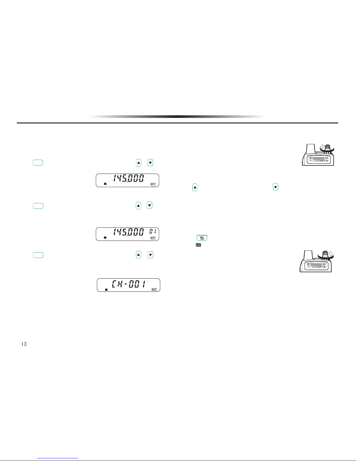
BASIC MODES BASIC MODES
There are 3 basic modes available for selection:
■ VFO MODE(FREQUENCY DISPLAY MODE)■ VFO MODE(FREQUENCY DISPLAY MODE)
Press key to proceed with selection. You can use / to
change the frequency, or use keypad to input the frequency required
directly.
■ MR MODE (MEMORY RECALL MODE)■ MR MODE (MEMORY RECALL MODE)
Press key to proceed with selection. You can use / or
input the frequency required directly, or change the frequency
(freauency and relative data saved). You have to save at least one
memory channel or you cannot enter into the mode.
■ CH MODE (CHANNEL DISPLAY MODE)■ CH MODE (CHANNEL DISPLAY MODE)
Press key to proceed with selection. You can use / or
keypad to input the frequency required directly, change the
frequency (freauency and relative data saved). You have to save at
least one memory channel or you cannot enter into the mode.
SWITCH POWER ON/OFFSWITCH POWER ON/OFF
1.Turn the Power/Volume Knob clockwise to turn on the transceiver.
•A music tone sounds.
2.To turn it off, turn the Power/Volume Knob counterclockwise.
S
F
S
V/M
R.
V/M
R.
V/M
R.
F
S
ADJUST THE VOLUMEADJUST THE VOLUME
1.Rotate the Power/Volume knob clockwise to increase the volume.
2.Rotate it counterclockwise to decrease the volume.
•If you cannot hear clearly due to squelch function,
press and hold [MONI] and rotate the power/volume
knob, then you can hear the background noise.
SELECT A FREQUENCYSELECT A FREQUENCY
Use key to increase the frequency, and key to decrease it.
•If you cannot select a specific frequency, the frequency step size
needs to be changed. See ‘’CHANGING FREQUENCY STEP SIZE’’.
•You can also input the frequency required directly with the keypad.
SELECT AN OUPPUT POWERSELECT AN OUPPUT POWER
Press to select Hi/Lo output power .
•If appears on LCD display, it shows the output power is low.
Note: If voice receiving is clear within communication
range, please select low output power to reduce
battery consumption and extend its life.
TRANSMITTRANSMIT
1.When ready to transmit, press the [PTT] switch and speak into the
microphone in your normal speaking voice.
•The lamp lights red when transmit.
•If you are too close to microphone or spead too loudm the distortion
may increase and the clarity of your signal to the receiving party may
reduce.
2.Release the [PTT] switch to receive.
ADJUST THE VOLUME
1.Rotate the Power/Volume knob clockwise to increase the volume.
2.Rotate it counterclockwise to decrease the volume.
•If you cannot hear clearly due to squelch function,
press and hold [MONI] and rotate the power/volume
knob, then you can hear the background noise.
SELECT A FREQUENCY
Use key to increase the frequency, and key to decrease it.
•If you cannot select a specific frequency, the frequency step size
needs to be changed. See ‘’CHANGING FREQUENCY STEP SIZE’’.
•You can also input the frequency required directly with the keypad.
SELECT AN OUPPUT POWER
Press to select Hi/Lo output power .
•If appears on LCD display, it shows the output power is low.
Note: If voice receiving is clear within communication
range, please select low output power to reduce
battery consumption and extend its life.
TRANSMIT
1.When ready to transmit, press the [PTT] switch and speak into the
microphone in your normal speaking voice.
•The lamp lights red when transmit.
•If you are too close to microphone or spead too loudm the distortion
may increase and the clarity of your signal to the receiving party may
reduce.
2.Release the [PTT] switch to receive.
BASIC OPERATION BASIC OPERATION
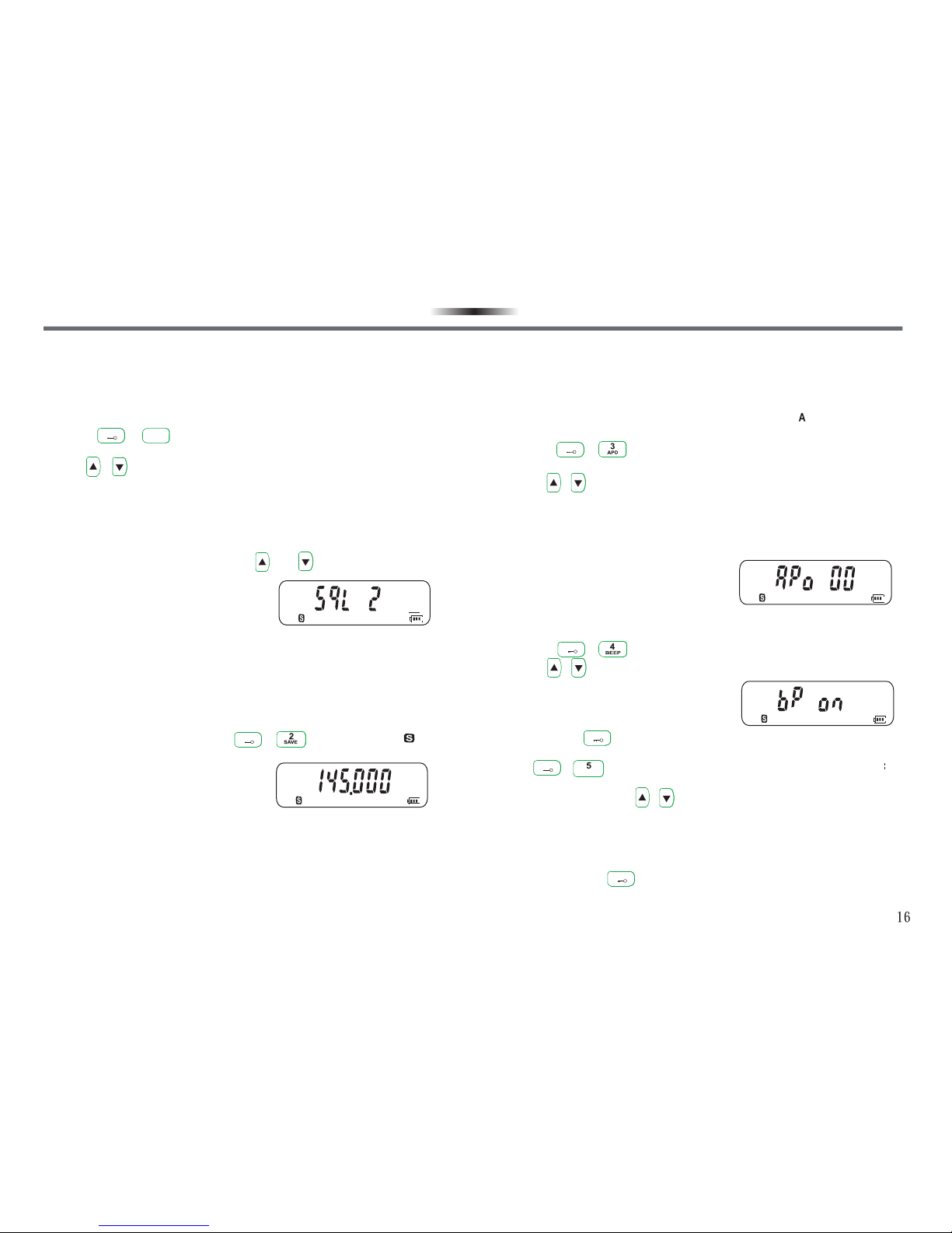
ADJUST SQUELCH (SQL)ADJUST SQUELCH (SQL)
The purpose of the Squelch is to mute the speaker when no signals
are present (squelch circuit closed). With the squelch level correctly
set, you will hear sound only when actually receiving a signal (squelch
circuit open).
1.Press + keys.
•The present squelch level appears.
2.Use / to select the squelch level within the range of 0-9
(default value :2).
•Select a level at which the background noise is just eliminated
when no signal is present.
•The larger the level number you select, the stronger the signal
you need to receive, and the smaller the receiving range.
3.Press any key other than [LAMP], ,and to complete the
setting.
BATTERY SAVER (SAVE)BATTERY SAVER (SAVE)
The battery saver function decreases the power consumption by
reducing circuit when a signal is not being received, so as to extend
the battery life. When squelch level is 0 or Battery Saver key is
pressed again, battery saver will be disabled. You can switch this
function ON or OFF by pressing + . When it is ON,
will appear.
F
1
SQL
F
AUTOMATIC POWER OFF (APO)AUTOMATIC POWER OFF (APO)
Automatic Power Off is a background function that monitors whether
any keys have been pressed, or whether any knobs have been turned.
If no operation within one hour, APO will automatically turn off the
power. However, 1 minute before the power turns off, will flash and a
warning beep sounds.
1.Press + .
•Turn on/off APO.
2.Use / to select the setting time within the range of 0-15
(Default value : 00).
•If the squelch opens or any settings are changed during the setting
time period while APO is ON, the timer resets. When the squelch
closes or you stop changing the settings, the timer begins counting
again from 0.
KEYPAD BEEPER (BEEP)KEYPAD BEEPER (BEEP)
The transceiver beeps each time if you press a key on the keypad. You
can use the following to turn on or off the beeper (Default : on).
1.Press + to enter into the beeper setting.
2.Use / to select on (bP on)/off(bP off).
KEYPAD LOCK (LOCK)KEYPAD LOCK (LOCK)
Press and hold key for 3 seconds to lock keys. There are 4 lock
modes for you to control the lock way for your transceiver .
Press + keys to enter into setting, there are 4 lock ways lock
ways available.
1.Loc S : Keypad and / keys re locked.
2.Loc P : Only lock the [PTT] switch to prevent the transceiver from
being wrongly transmitted by yourself or others.
3.Loc n : Only lock the keypad to prevent the setting from being
changed incidentally.
4.Loc A : Except ,[LAMP] keys, the remaining keys are all
locked.
F
F
F
F
F
LOCKLOCK
15
FUNCTION SETTING AND DESCRIPTION FUNCTION SETTING AND DESCRIPTION

RECEIVE WITH CTCSS/DCSRECEIVE WITH CTCSS/DCS
Sometimes you may only need to receive calls from specific persons.
CTCSS/DCS allows you not to hear unwanted calls from other persons
who are using the same frequency. You can select the set required from
51 sets of CTCSS and 107 sets of DCS.
Note : It cannot be guaranteed to keep your private talk secret, it only ensures that
you will not receive the calls from other group persons using the same frequency.
1.Under VFO/MR mode, press + to enter into ‘’Receive with
CTCSS/DCS’’.
2.Use / to select the following 4 modes:
• :Receive without CTCSS/DCS.
• :Receive with CTCSS.
• :Receive with normal DCS.
• :Receive with inverted DCS.
3.Select the mode required and press key to confirm your setting
and enter into the next setting selection.
•If select , exit “Receive with CTCSS/DCS” mode directly, the
transceiver will return back to the present operation mode.
•If select , the LCD display show , that is the first
CTCSS frequency, you can use / keys to select the audio
frequency required, then press key to confirm your setting.
“Receive with CTCSS” function will be activated, and the transceiver
will return back to the present operation mode.
•If select , the LCD display shows , that is the first
normal DCS frequency, you can use / keys to select the normal
DCS frequency required, then press key to confirm your setting.
“Receive with normal DCS” function will be activated, and thetrans-
ceiver will return back to the present operation mode.
•If select , the LCD display shows , that is the first
inverted DCS frequency, you can use / keys to select the
inverted DCS frequency required, then press key to confirm
your setting. “Receive with inverted DCS” function will be activated,
and the transceiver will return back to the present operation mode.
F
RSQTRSQT
F
F
F
F
TRANSMIT WITH CTCSS/DCS
1.Under VFO/MR mode, press + to enter into “Transmit with
CTCSS/DCS”.
2.Use / to select the following 4 modes:
• :Transmit without CTCSS/DCS.
• :Transmit with CTCSS.
• :Transmit with normal DCS.
• :Transmit with inverted DCS.
3.Select the mode required and press key to confirm your setting
and enter into the next setting selection.
•If select , exit “Transmit with CTCSS/DCS” mode directly,
the transceiver will return back to the present operation mode.
•If select , the LCD display shows , that is the first
CTCSS frequency, you can use / keys to select the audio
frequency required, then press key to confirm your setting.
“Transmit with CTCSS” function will be activated, and the transceiver
will return back to the present operation mode.
•If select , the LCD display shows ,that is the first
normal DCS frequency, you can use / keys to select the
normal DCS frequency required, then press key to confirm
your setting. “Transmit with normal DCS” function will be activated,
and the transceiver will return back to the present operation mode.
•If select ,the LCD display shows , that is the first
inverted DCS frequency, you can use / keys to select the
inverted DCS frequency required, then press key to confirm
your setting. “Transmit with inverted DCS” function will be activated,
and the transceiver will erturn back to the present operation mode.
Note :
1.CTCSS/DCS functions cannot be activated under CH mode.
2.When you have set CTCSS/DCS during transmitting or receiving, LCD display
will show the corresponding “ ”, “ ” or “ ”.
3.When selecting modes and numeric values, you have to finish delection within
10 seconds, or the transceiver will return back to the present operation mode,
and you have to operate according to the above steps from the beginning.
TSQTTSQT
FUNCTION SETTING AND DESCRIPTION FUNCTION SETTING AND DESCRIPTION
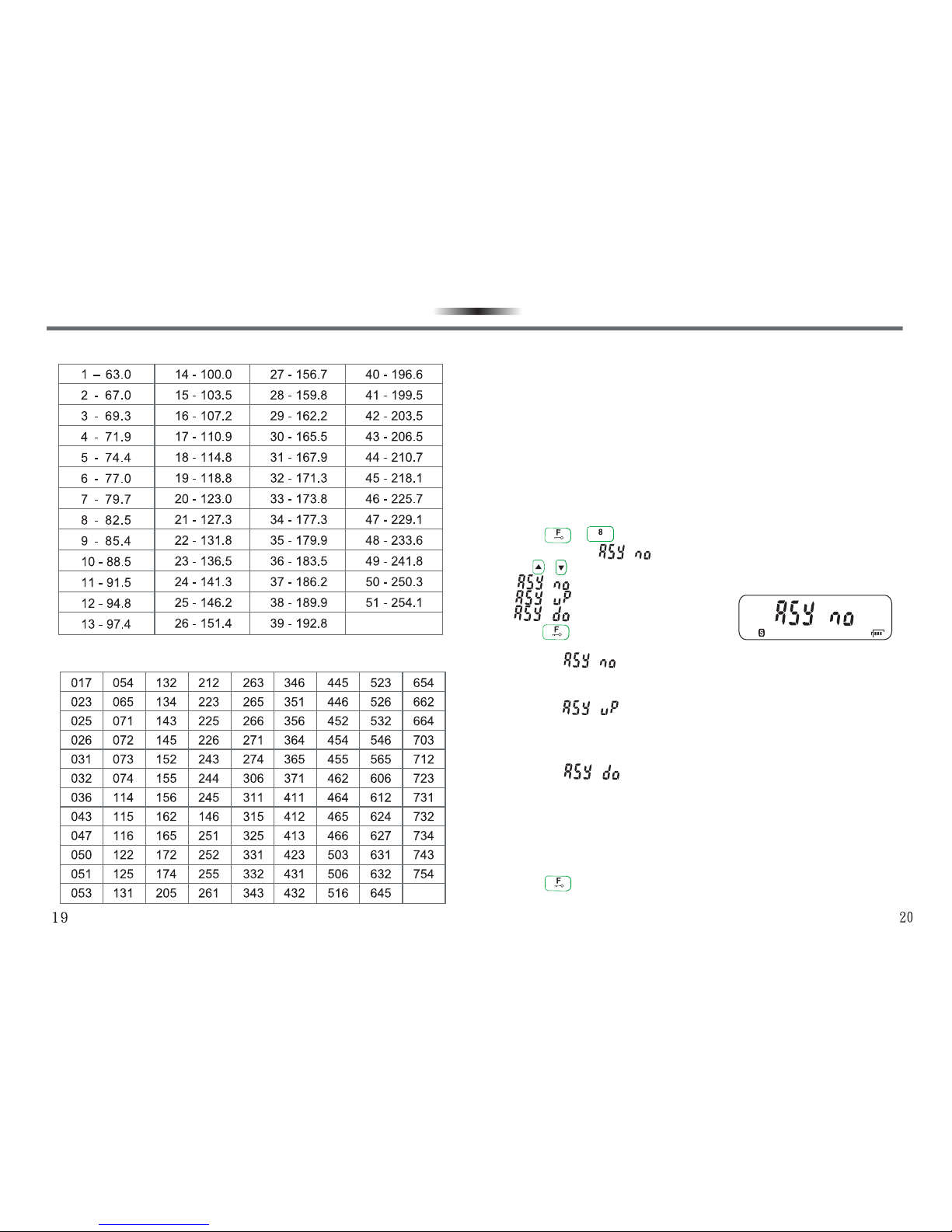
CTCSS STANDARD FREQUENCY TABLE
DCS STANDARD SETS
SETTING OFFSET DIRECTION AND OFFSET FREQUENCY (ASY)SETTING OFFSET DIRECTION AND OFFSET FREQUENCY (ASY)
Comparing with simplex communication, repeater communication can trasmit
signals further. Repeaters are often located on a mountain top or other elevated
location. They often operate at higher ERP (Effective Radiated Power) than
general stations. The combination of elevation and high EPR allows considerable
communication distance. Most repeaters use separate receiving and transmitting
frequencies. You can select the receiving and transmitting frequencies required
when programming the channel (Depended on the repeater frequency you are
accessing).
1.Press + keys to enter into offset direction setting . LCD
display shows “ ”.
2.Use / to select one among the following 3 modes:
• :without offset frequency.
• :positive offset frequency.
• :negative offset frequency.
3.Press key again to confirm offset direction, and enter into the
next setting selection.
•If select , “without offset frequency” is selected, and the
transceiver will exit the setting mode directly, and return back to VFO
mode.
•If select , ”positive offset frequency” is selected, and the
LCD display shows 01.000. At the meantime, you can input the
positive offset frequency required through the keypad (input range :
00.000 - 99.995).
•If select , “negative offset frequency” is selected, and the
LCD display shows 01.000.At the meantime, you can input the
negative offset frequency required through the keypad (input range
:00.000 - 99.995).
Note:The combined frequency value of the offset frequency input and the present frequency,
must be within the frequency range of the transceiver, or offset frequency and offset direction
settings will be invalid.
4.Press again to complete the setting, the transceiver will return
back to VFO operation mode.
REVREV
FUNCTION SETTING AND DESCRIPTION FUNCTION SETTING AND DESCRIPTION
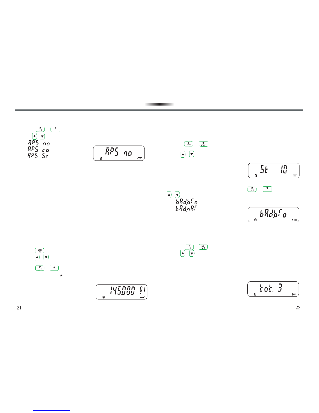
VOICE COMPANDER/SCRAMBLER (APS)VOICE COMPANDER/SCRAMBLER (APS)
APS offers 3 modes for selection, default setting is OFF.
1.Press + to enter into APS.
2.Use / keys to select.
• :Without compander/scrambler function.
• :Voice Compander.
• :Voice Scrambler.
-Voice Compander (Co)
Voice Compander is an advanced audio frequency technique to
suppress noise and enhance voice quality. This technique can bring
more clear and melodious voice for you to keep smooth communication
in noisy environment.
-Voice Scrambler (Sc)
Voice Scrambler can keep your conversation fully private. The
transceiver recombines audio frequency and then transmits, making
only communication group members with the same voice scrambler can
receive your calls, otherwise the other transceivers cannot understand
your conversation.
MEMORY CHANNEL SCAN LOCK/UNLOCK (S.A/D)MEMORY CHANNEL SCAN LOCK/UNLOCK (S.A/D)
Sometimes you may hope some memory channels not to be scanned
under scan mode. In the meantime, you can lock/unlock the memory
channel monitored under scan (Default : On).
1.Press key to enter into memory recall mode under VFO mode.
2.Press / keys to select the Memory Channel you need to
lock/unlock.
3.Press + keys to complete lock/unlock.
•If LCD displays “ ” in the right, it means the channel has been
locked; if it doesn’t display, the channel has not been locked.
SCRSCR
SA / DSA / D
FREQUENCY STEP SETTINGFREQUENCY STEP SETTING
If you cannot find the specific frequency, you have to change frequency
intervals. It is the basic condition of selecting accurate receiving
frequency to select an accurate frequency interval. Default value:10
KHz.
1.Press + to enter into Frequency Step Setting under VFO
mode.
2.Use / keys to select a frequency interval.
•The frequency intervals available are 5,6.25,10,12.5,25 KHz.
BROAD/NARROW BAND (W/N)BROAD/NARROW BAND (W/N)
You can enter into Broad/Narrow band with + keys, and use
/ keys to select the band width you need. Default value : Broad.
• :Broad band, 25KHz.
• :Narrow band, 12.5KHz.
TIME OUT TIMER (TOT)TIME OUT TIMER (TOT)
Uncertain continuous transmissions will do harm to a transceiver. In
order to protect it from thermal damage, before the transmission time
limit is over, a warning beep sounds. The default setting is 3 Min.
1.Press + to enter into Time out timer setting.
2.Use / keys to select the time limit.
•The time limits available : 1-8 minutes and OFF.
•If your continuous transmissions excedeed the time limit, the
transceiver will stop transmission and a ‘‘beep’’ sounds. If you want
to stop the “beep” sound, release PTT key to restore to normal
situation.
W / NW / N
FUNCTION SETTING AND DESCRIPTION FUNCTION SETTING AND DESCRIPTION

SCAN (SCAN)SCAN (SCAN)
It allows you to monitor the frequencies you want without the necessity
of operating manually. After being familiar with various scan modes, you
will increase your efficiency from flexibility of monitoring.
The transceiver provides with the following scan modes :
•VFO frequency scan : All frequencies in the entire band.
•Memory channel scan : Channels stored in the internal memory
channel.
SCAN METHODSCAN METHOD
Before using scan, it’s necessary to decide under what condition you
want your transceiver to continue scanning after detecting and stopping
for a signal. You can select one of the following modes :
•Time-Operated Mode (TO)
The transceiver stops scanning when detecting a signal,
remaining for about 5 seconds, and then continues to scan even if
the signal is still present.
•Carrier-Operated Mode (CO)
The transceiver stops scanning when detecting a signal,
remaining on the same channel until the signal disappears. There
is a 2 seconds delay between signal disappearance and scan
resumption to allow time for any responding stations to begin
transmitting.
Note : Press any key other than LAMP, / will make the transceiver stop
scanning.
SELECTING SCAN METHODSELECTING SCAN METHOD
1.Press + to enter into Scan method selection.
2.Use / keys to select :
• :Carrier - Operated Mode.
• :Time - Operated Mode.
VFO SCANVFO SCAN
VFO scan allows you to scan all frequencies from the lowest to the
highest frequency in the entire band.
1.Press key to begin scanning under VFO mode.
•The scan will begin from the present frequency displayed on the
LCD.
•To control scan direction, press key to scan forward, or key
to scan backward.
2.To cancel VFO scan, press any key other than LAMP, / .
MEMORY CHANNEL SCANMEMORY CHANNEL SCAN
Memory channel scan allows all stored memory channles to be
scanned.
1.Press key to enter into Memory channel scan.
2.Press key to begin scanning.
•Scan starts with the channel last recalled.
•To control scan direction, press key to scan forward, or key
to scan backward.
3.To cancel Memory channel scan, press any key other than LAMP,
/ .
Note:
1.You have to store at least 2 memory channels without being locked so that you
can proceed with memory channel scan.
2.The squelch function must be closed for scan to function.
3.You can proceed with memory channel scan under channel display mode.
FUNCTION SETTING AND DESCRIPTION FUNCTION SETTING AND DESCRIPTION

MEMORY CHANNEL
You can store frequencies and common settings under memory channel
so that you do not need to reset these data from the beginning every
time. Just a simple operation can call the frequency you need. There
are 199 memory channels available, you can store channels by
frequency-writing software at dealers.
STORING MEMORY CHANNELSTORING MEMORY CHANNEL
1.Input the frequency you need under VFO mode.
2.Press key, and will flash on the LCD display.
•The memory channel number will appear in the upper right corner.
3.Use / key to select the channel number where you want to
store the frequency.
4.Press key to confirm the setting and return back to VFO mode.
•The frequency selected and the related data will be stored in the
memory channel.
•If the memory channel selected in Step 3 has data in it, the new
data will replace the old one.
Note : Before storing the memory channel, please confirm if the receiving /
transmitting squelch numbers and the related settings have fully been set.
USING MEMORY CHANNELUSING MEMORY CHANNEL
1.Press key to enter into memory recall mode.
•The memory channel used last appears in the LCD display. If this
is the first time you use, then the least channel number will
appear.
2.Use / keys to select the memory channel you would like to
use.
•If you want to resume to VFO mode, press key to switch.
Note : The memory channel must have data stored or it cannot be used.
MEMORY CHANNEL
INITIALIZING MEMORYINITIALIZING MEMORY
If your transceiver seems to be malfunctioning, initializing the
transceiver may resolve the problem. Remember that you have to
reprogram memory channels after initizlization. On the other hand,
initialization is a quick way to clear alll memory channels.
FULL RESET INITALIZATION (MEMORY MODE)FULL RESET INITALIZATION (MEMORY MODE)
Used to initialize all settings.
1.Press key and hold, and turn on the power switch.
•Release key after turning on the power switch.
•The LCD display will show a menu for selection.
2.Press key, will appear for you to confirm if all
settings will be reset.
•The LCD display appears a menu for selection.
3.Press key to finish setting.
PARTIAL RESET INITIALIZATION (VFO MODE)PARTIAL RESET INITIALIZATION (VFO MODE)
Used to initialize all settings except memory channel / memory channel
lock.
1.Press key and hold, and turn on the power seitch.
•Release key after turning on the power switch.
•The LCD display will show a menu for selection.
2.Use / to select “ ”.
•The LCD display appears a menu for selection.
3.Press key to finish confirmation and return back to VFO mode.

MAINTENANCE
USAGE AND MAINTENANCE INSTRUCTIONUSAGE AND MAINTENANCE INSTRUCTION
•Keep the transceiver dry. Rain, moisture, all kinds of liquid and water
may lead to circuit corrosion. If it is wet, remove the battery. Please
don’t install the battery until the transceiver is fully dry.
•Don’t keep the transceiver in dusty or dirty places, which will damage
the detachable parts and electronics components.
•Don’t keep the transceiver in overheated places. High temperature
will shorten the life of electronics equipments, destroy batteries, and
deform or melt some plastic parts.
•Do not place the transceiver in over cooling places. Otherwise when
it reaches the normal temperature, internally generated moisture will
destroy printing circuit boards.
•Turn on the transceiver according to the instruction of the manual,
never try other methods.
•Never drop, knock, or shake the transceiver. Treat it rudely will
damage internal printing circuit boards and precision structures.
•Never use strong chemicals, cleaning agents, or detergents to clean
the transceiver.
•Do not paint the transceiver with pigments. The painting may form a
clog in the detachable parts and affect normal operation.
•Don’t hold the antenna directly or have an external microphone
connection.
•When replacing an antenna, use only the one accompanied with the
kit or an approved one. An unapproved, refitted one may damage the
transceiver.
•Please charge indoors.
•Cover with the earphone plug when the transceiver is not in use.
•Please backup the necessary data (such as frequencies and
channels) before you send your transceiver to an authorized repair
station for service.
The above suggestions equally apply to your transceiver, battery, charger, and
every accessory. If any equipment cannot operate properly, pleae forward to an
authorized repair station for service.
For accuracy, the information contained in the manual has been checked carefully.
If there are still any possible printing mistakes or translation errors, please feel
free to point out. reserves the right to change the product setting and
specification without prior notice.
28
MEMORY CHANNEL
CHANNEL RESET INITIALIZATION (MR MODE)CHANNEL RESET INITIALIZATION (MR MODE)
Used to initalize memory recall mode.
1.Confirm the channel mode is under MR mode, and select the
memory channel you would like to delete.
2.Press key and hold, and turn on the power switch.
•Release key after turning on the power switch.
•The LCD display will show a menu for selection.
3.Then use / key and select “ ”.
•The LCD display will show a menu for selection.
4.Press key to finish confirmation, and the LCD display will show
the memory channel next to the deleted one.
This manual suits for next models
1
Table of contents
Other ADI Transceiver manuals


