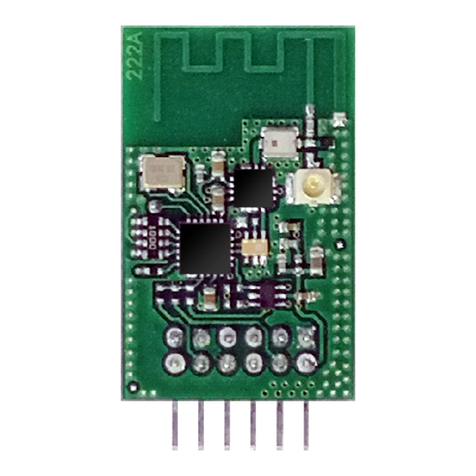
ADIMOS Systems WVM-1101 User manual

ADIMOS Systems Ltd. ** Company Confidential **
WVM User Manual Page 1of 1Rev 1.00
Adimos Wireless Video Module
User Manual
Model: WVM-1101
The material contained herein is proprietary, privileged, and confidential.
No disclosure thereof shall be made to third parties without the express written
permission of ADIMOS Systems Ltd.
ADIMOS Systems Ltd. reserves the right to alter the equipment specifications and
descriptions in this publication without prior notice. No part of this publication shall be
deemed to be part of any contract or warranty unless specifically incorporated by
reference into such contract or warranty.

ADIMOS Systems Ltd. ** Company Confidential **
WVM User Manual Page 2of 2Rev 1.00
Table of Contents
1. Introduction ..................................................................................................................................3
1.1 Purpose andScope...................................................................................................................3
1.2 Terms and Abbreviations ..........................................................................................................3
2. References .....................................................................................................................................3
3. Configuration and Status Registers...............................................................................................3
3.1 General Description.................................................................................................................3
3.2 Register Details.......................................................................................................................3
3.2.1 Introduction .....................................................................................................................3
3.2.2 Register Summary............................................................................................................4
3.2.3 System Version ................................................................................................................5
3.2.4 Video standard .................................................................................................................5
3.2.5 Video input port ...............................................................................................................6
3.2.6 Video rate........................................................................................................................6
3.2.7 Country Code...................................................................................................................7
3.2.8 WLAN channel................................................................................................................7
3.2.9 Operationmode –local unit ..............................................................................................8
3.2.10 Operationmode –remote unit ...........................................................................................8
3.2.11 Timeout and Status of the Wireless I2C..............................................................................9
3.2.12 IR enable/disable ..............................................................................................................9
3.2.13 Discrete Inputs Status .....................................................................................................10
3.2.14 Wireless ID....................................................................................................................10
3.2.15 RSSI Status ....................................................................................................................10
3.2.16 PERStatus .....................................................................................................................10
3.2.17 Do Installation Process....................................................................................................11
3.2.18 Discrete I/O Test Mode...................................................................................................11
3.2.19 Reset unit .......................................................................................................................11

ADIMOS Systems Ltd. ** Company Confidential **
WVM User Manual Page 3of 3Rev 1.00
1. Introduction
1.1 Purpose and Scope
The Wireless Video Module product (WVM-1101) delivers video over wireless channel. It enables a
wireless connection between a video source (DVD, VCR, PVR, STB, BS or PC) and a video display
(standard TV, flat screen TV or video monitor).
WVM-1101 operates in 5.15-5.35GHz.
This document guides the user how to configure the WVM via a set of configuration and status registers.
1.2 Terms and Abbreviations
BS Base Station
CPU A microprocessor or microcontroller device
DVD Digital Video Disk
MPEG Motion Picture Expert Group
N/A Not Applicable
PVR Personal Video Recorder
STB Set Top Box
VCR Video Cassette Recorder
WLAN Wireless Local Area Network
WVM Wireless Video Module
2. References
[1] Adimos WVM -Frequency Channel Tables
3. Configuration and Status Registers
3.1 General Description
The WVM provides a set of internal registers, which can be modified or read via I2C interface. The values
of these registers determine the behavior of the WVM. Each register has a unique sub-address.
3.2 Register Details
3.2.1 Introduction
This section describes the internal registers.
•Byte order: Byte0 is the first byte in a read/write operation.
•Bit order: Bit 7 is the most significant bit within a byte.
•0x… is a hexadecimal number.

ADIMOS Systems Ltd. ** Company Confidential **
WVM User Manual Page 4of 4Rev 1.00
3.2.2 Register Summary
Sub-address Name Side Read/
Write Size
[bytes] Function
0x00 System Version Tx, Rx
R4System version ID
0x01 Set video standard Tx R/W 2Set NTSC/PAL/SECAM/Auto.
0x02 Video standard status Tx, Rx
R1Actual status of video standard
0x03 Select video input port Tx R/W 2Select Composite-video, S-Video,
Component-video or Auto.
Applicable only to WVM1103.
0x04 Video input port status Tx, Rx
R1Actual status of video input port.
Applicable only to WVM1103.
0x05 –0x08 Reserved ---- ---- ----
0x09 Set video rate Tx R/W 2Set video bit rate
0x0A Video rate status Tx, Rx
R1Actual status of video bit rate
0x0B –0x0F Reserved ---- ---- ----
0x10 Country Code Tx, Rx
R/W 2Set Country code for WLAN
0x11 Set WLAN channel Tx R/W 2Set frequency channel for WLAN
0x12 WLAN channel status Tx, Rx
R2Actual status of WLAN channel
0x13 Change operation mode Tx, Rx
W1Change the operation mode at the local
unit
0x14 Operation mode status Tx, Rx
R1Actual operation mode at the local unit
0x15 Wireless I2C timeout Tx R/W 1Set timeout for error conditions
0x16 Wireless I2C status Tx R1Status of last transaction
0x17 IR Enable/Disable RxR/W 1Enable/Disable the IR function
0x18 Reserved ---- ---- ----
0x19 Discrete Inputs status Rx R1Status of Discrete Inputs of the Tx
unit.
0x1A Wireless ID Rx R16 Value of wireless ID string
0x1B RSSI status Tx, Rx
R1Status of signal strength
0x1C –0x1E Reserved ---- ---- ----
0x1F PER status Tx, Rx
R1Status of Packet Error Rate
0x20 Remote operation mode
change request Tx, Rx
W1Request a change of the operation
mode at the remote unit
0x21 Change request status Tx, Rx
R1Status of change request
0x22 Do installation process Tx W1Initiate installation process
(Tx-Rx synchronization)
0x23 Discrete I/O test Tx, Rx
R/E 1Test mode for the Discrete I/O’s
0x24 –0x50 Reserved ---- ---- ----
0x51 Reset unit Tx, Rx
W1Unit reset command
Notes:
•The Side column designates if the register is applicable to both Tx and Rx units, Tx only or Rx only.
•The Read/Write column designates if the register is Read only (R), Read and Write (R/W) or Write only
(W).
•The Size column designates the number of bytes in the register, e.g. 1, 2 or 4.

ADIMOS Systems Ltd. ** Company Confidential **
WVM User Manual Page 5of 5Rev 1.00
3.2.3 System Version
Sub-
addr Name R/W Size
[bytes] Value Default
0x00 System Version R4Byte0: V1
Byte1: V2
Byte2: V3
Byte3: V4
Byte values are 0-0xFF
N/A
The System version is presented as: V1.V2.V3.V4.
V1 –Product type
V2 –Major version ID
V3, V4 –Minor version ID
3.2.4 Video standard
Sub-
addr Name R/W Size
[bytes] Value Default
Byte0 = 1: NTSC
Byte0 = 2: PAL
Byte0 = 3: SECAM
Byte0 = 0xFF: N/A (only on Read)
1
(NTSC)
0x01 Set video
standard
(Tx only)
R/W 2
Byte1 = 0: Fixed
Byte1 = 1: Automatic (Byte0 is ignored)
Byte1 = 0xFF: N/A (only on Read)
1
(Automatic)
0x02 Video standard
status R1Byte0 = 0: No video signal
Byte0 = 1: NTSC
Byte0 = 2: PAL
Byte0 = 3: SECAM
N/A
The video standard at the video input can be set to NTSC, PAL or SECAM, or can be set to Automatic.
When set to Automatic, the system will select automatically the appropriate video standard, according to the
actual input signal.
Writing to register 0x01 commands the system to a desired video standard.
Reading from register 0x02 presents the video standard that is currently active.

ADIMOS Systems Ltd. ** Company Confidential **
WVM User Manual Page 6of 6Rev 1.00
3.2.5 Video input port
Sub-
addr Name R/W Size
[bytes] Value Default
Byte0 = 1: Composite video
Byte0 = 2: S-Video
Byte0 = 3: YPbPr-interlaced video
Byte0 = 0xFF: N/A (only on Read)
1
(Composite
video)
0x03 Select video
input port
(Tx only)
R/W 2
Byte1 = 0: Fixed
Byte1 = 1: Automatic (Byte0 is ignored)
Byte1 = 0xFF: N/A (only on Read)
1
(Automatic)
0x04 Video input port
status R1Byte0 = 0: No video signal
Byte0 = 1: Composite video
Byte0 = 2: S-Video
Byte0 = 3: YPbPr-interlaced video
N/A
The video input can be selected among YPbPr (component) input with interlaced video, S-Video and
Composite video, or set to Automatic.
When set to Automatic the Tx unit will perform automatic detection of a video signal in the following order
of precedence:
-YPbPr-interlaced video
-S-Video
-Composite Video.
Writing to register 0x03 commands the system to a desired video input port.
Reading from register 0x04 presents the video input port that is currently active.
Note: Register 0x03 and 0x04 are applicable only to WVM1103 model.
3.2.6 Video rate
Sub-
addr Name R/W Size
[bytes] Value Default
Byte0 = 1: 4 Mbps
Byte0 = 2: 8 Mbps
Byte0 = 3: 14 Mbps
Byte0 = 4-7: reserved
Byte0 = 0xFF: N/A (only on Read)
3
(14 Mbps)
0x09 Set video rate
(Tx only) R/W 2
Byte1 = 0: Fixed rate
Byte1 = 1: Limited Automatic rate (up to
the rate set by Byte0)
Byte1 = 2: Fully Automatic rate (Byte0 is
ignored)
Byte1 = 0xFF: N/A (only on Read)
2
(Fully
Automatic)
0x0A Video rate
status R1Byte0 = 0: No video transfer
Byte0 = 1: 4 Mbps
Byte0 = 2: 8 Mbps
Byte0 = 3: 14 Mbps
N/A

ADIMOS Systems Ltd. ** Company Confidential **
WVM User Manual Page 7of 7Rev 1.00
The video transmission rate can be set to 4, 8 or 14 Mbps, or can be set to Limited Automatic or Fully
Automatic.
When set to Limited Automatic, the system will select automatically the highest possible video rate, up to
the value set in Byte0 of register 0x09. This setting may be used when the user wants to limit the system to 4
or 8 Mbps only, without trying to go to 14 Mbps.
When set to Fully Automatic, the system will select automatically the highest possible video rate.
Writing a value to register 0x09 commands the system to a desired video rate.
Reading from register 0x0A presents the video rate currently used by the system (i.e., the fixed video rate set
by the user or the video rate selected automatically be the system).
3.2.7 Country Code
Sub-
addr Name R/W Size
[bytes] Value Factory
Setup
0x10 Set Country R/W 2Byte1:Byte0 = 0x8000 –0x8FFF: see
[1] -Country Code table According to
target
country
Text convention: If Byte1:Byte0 = 0x1234 then Byte0 is 0x34 and Byte1 is 0x12.
The WLAN Country code can be set to one of the permitted values.
Writing to register 0x10 commands the system to a desired Country code. The Country code must be set
both at the Tx and Rx unit.
Note: Trying to write an illegal Country Code will be ignored; the value of the register will not change.
3.2.8 WLAN channel
Sub-
addr Name R/W Size
[bytes] Value Default
Byte0 = 1, 2, … : Index of a fixed
channel in the list of permitted
channels, according to configured
Country code.
Byte0 = 0xFF: N/A (only on Read)
10x11 Set WLAN channel
(Tx only) R/W 2
Byte1 = 0: Fixed channel
Byte1 = 1: Automatic channel (Byte0
is ignored)
Byte1 = 0xFF: N/A (only on Read)
1
(Automatic)
Byte0 = Channel number, according to
Channel Table below, of actual
channel.
N/A0x12 WLAN channel
status R2
Byte1 = Index of actual channel in the
list of permitted channels, according to
configured Country code.
N/A
The WLAN frequency channel can be set to one of the permitted channels, according to configured Country
code, or can be set to Automatic.
When set to Automatic, the system will select automatically the best available channel.
Writing to register 0x11 commands the system to a desired mode and channel.
Reading from register 0x12 presents the channel currently used by the system.

ADIMOS Systems Ltd. ** Company Confidential **
WVM User Manual Page 8of 8Rev 1.00
Channel Table
Channel
Number
(Hex)
Channel
Frequency
(GHz)
Channel
Number
(Hex)
Channel
Frequency
(GHz)
Channel
Number
(Hex)
Channel
Frequency
(GHz)
22 5.170 64 5.500 95 5.745
24 5.180 68 5.520 99 5.765
26 5.190 6C 5.540 9D 5.785
28 5.200 70 5.560 A1 5.805
2A 5.210 74 5.580 A5 5.825
2C 5.220 78 5.600
2E 5.230 7C 5.620
30 5.240 80 5.640
34 5.260 84 5.660
38 5.280 88 5.680
3C 5.300 8C 5.700
40 5.320
3.2.9 Operation mode–local unit
Sub-
addr Name R/W Size
[bytes] Value Default
0x13 Change
operation mode W1Byte0 = 0: Enter Sleep mode
Byte0 = 1: Exit Sleep mode N/A
0x14 Operation mode
statusR1Byte0 = 0: Sleep mode
Byte0 = 1: Idle mode
Byte0 = 2: Work mode
N/A
Notes:
•Enter Sleep Mode command is applicable only when the unit is in Idle or Work mode. Entering Sleep
mode stops any video and audio transfer.
•Exit Sleep Mode command is applicable only when the unit is in Sleep mode. The unit will switch to
Idle mode.
3.2.10 Operation mode–remote unit
Sub-
addr Name R/W Size
[bytes] Value Default
0x20 Remote
operation mode
change request
W1Byte0 = 0: Request to enter Sleep
mode on the remote unit
Byte0 = 1: Request to exit Sleep
mode on the remote unit
N/A
0x21 Change request
status R1Byte0 = 0: Success of change request
Byte0 = 1: Failure of change request
Byte0 = 2: Request in progress
N/A

ADIMOS Systems Ltd. ** Company Confidential **
WVM User Manual Page 9of 9Rev 1.00
Notes:
•Enter Sleep mode request is applicable only when the remote unit is in Idle or Work mode. Entering
Sleep mode stops any video and audio transfer.
•Exit Sleep mode request is applicable only when the remote unit is in Sleep mode. The unit will switch
to Idle mode.
•Register 0x21 shows the status of the last change request.
When the request is in progress, the register will be set to 2.
In case of failure in executing the command (e.g., the remote unit is off), the register will be set to 1. It
may take approximately 1 sec. to set the register to Failure value.
In case of successful execution the register will be set to 0.
The Success/Failure condition will remain set until the next request will start.
3.2.11 Timeout and Status of the Wireless I2C
Sub-
addr Name R/W Size
[bytes] Value Default
0x15 Wireless I2C
timeout
(Tx only)
R/W 1Byte0 = 0-0xFE: timeout, in
10 mSec units
Byte0 = 0xFF: N/A (only on Read)
0x1E
(300 mSec)
0x16 Wireless I2C
status
(Tx only)
R1Byte0 = 0: Success
Byte0 = 1: Failed
Byte0 = 0xFF: N/A
N/A
Register 0x15 sets the timeout of the Wireless I2C function. It is applicable only to the Tx unit.
In case of failure in the Wireless I2C, while the SCL line is held low by the Tx unit, the unit will release the
SCL line after that timeout.
Register 0x16 presents the status of the last transaction. It is applicable only to the Tx unit.
In case of failure in the Wireless I2C transaction, this register will be set to 1. In case of a complete and
successful Wireless I2C transaction this register will be set to 0.
Note: The master should read this register only at the end of a Wireless I2C transaction. The Success/Failed
condition will remain set until the next transaction will start.
3.2.12 IR enable/disable
Sub-
addr Name R/W Size
[bytes] Value Default
0x17 IR
Enable/Disable
(Rx only)
R/W 1Byte0 = 0: Disabled
Byte0 = 1: Enabled
Byte0 = 0xFF: N/A (only on Read)
1
(Enabled)
The IR function can be enabled or disabled.

ADIMOS Systems Ltd. ** Company Confidential **
WVM User Manual Page 10of 10 Rev 1.00
3.2.13 Discrete Inputs Status
Sub-
addr Name R/W Size
[bytes] Value Default
0x19 Discrete Inputs
Status
(Rx only)
R1Byte0 = 0-7: Status of Discrete
Input 1, 2, 3 at the Tx unit.
Bit 0 is 1 when Discrete Input 1
is low; bit 1 corresponds to
Discrete Input 2 and bit 3
corresponds to Discrete Input 3.
N/A
The Discrete Inputs Status is updated when there is a change in the input status at the Tx unit.
3.2.14 Wireless ID
Sub-
addr Name R/W Size
[bytes] Value Default
0x1A Wireless ID
(Rx only) R16 Byte0-15 = Value of wireless ID
string. N/A
The Wireless ID string is a 128-bits (16-bytes) string, which identifies the Rx unit. It is used for
communicating to the Rx unit from a PC equipped with Adimos PC Connectivity product.
3.2.15 RSSI Status
Sub-
addr Name R/W Size
[bytes] Value Default
0x1B RSSI status R1Byte0 = 0-0x46 (0-70): RSSI in
dB units N/A
RSSI is an acronym for Received Signal Strength Indication. The RSSI value measures the signal relative to
a calibrated noise floor. The noise floor is measured over the relevant bandwidth over a long time, and the
minimum value establishes the calibrated noise floor.
The RSSI on the Rx side relates to the video stream direction; the RSSI on the Tx side relates to the
Acknowledge packets direction.
The RSSI is updated every 100 mSec.
3.2.16 PER Status
Sub-
addr Name R/W Size
[bytes] Value Default
0x1F PER status R1Byte0 = 0-0xC7 (0-199): PER in
0.5% units (e.g., 2 means PER of
1%)
Byte0 = 0xC8 (200): the unit is not
connected to a peer unit.
N/A
PER is an acronym for Packet Error Rate. While in video transmission, the PER is measured and updated at
the Tx unit every 300 mSec.
Special values of the PER status register:

ADIMOS Systems Ltd. ** Company Confidential **
WVM User Manual Page 11of 11 Rev 1.00
•When the unit is not connected, waiting for a peer unit to connect, PER status register is 200.
•When the unit is in sleep mode and connected to a peer unit, PER status register is 0.
3.2.17 Do Installation Process
Sub-
addr Name R/W Size
[bytes] Value Default
0x22 Do Installation
Process
(Tx only)
W1Byte0 = 1: Do normal installation
process
Byte0 = 2: Do temporary installation
process
N/A
The Installation Process is required for sending MAC and Wireless ID parameters from a Tx unit to a Rx
unit. After the two units are “synchronized”, video/audio transfer can be done.
The normal installation process writes the Tx details in the Rx, in a list of recognized Tx units. (The Normal
process is usually done by pressing the Installation button at the Tx unit).
The temporary installation process is for testing while in production. The Rx writes the Tx details in the list
of recognized Tx units, but deletes the details when the Tx-Rx wireless link is cut off.
3.2.18 Discrete I/O Test Mode
Sub-
addr Name R/W Size
[bytes] Value Default
0x23 Discrete I/O
Test R/W 1Byte0 = 0: Normal operation of the
Discrete I/O port
Byte0 = 1: Enter Discrete I/O test
mode
0
(Normal
operation)
The Discrete I/O Test Mode is required for production testing of Tx and Rx units.
When in Discrete I/O test mode, the 4 LEDs (pin 1, 2, 3, 4 of the Discrete I/O port) are turned on.
When pin 5, 6, 7 or 8 of the Discrete I/O port is shorted to GND, the LED of pin 1, 2, 3 or 4, respectively, is
turned off. All 4 input pins can be shorted to GND in any combination.
3.2.19 Reset unit
Sub-
addr Name R/W Size
[bytes] Value Default
0x51 Reset unit W1Byte0 = 1: Reset unit N/A
Writing 1 to register 0x51 will cause the WVM to reset and restart into Idle mode.

ADIMOS Systems Ltd. ** Company Confidential **
WVM User Manual Page 12of 12 Rev 1.00
4. Antenna:
Brand -NTK
Model -MAP5200AEA01
Detail specification –See attached
"Antenna with Brand
and Model Name 10-01-04.pdf"
Regulatory Information
Integrator must follow below instructions:
The Adimos WVM-1101 Wireless Video Module must be installed and used in strict accordance with the manufacturer’s
instructions as described in the user documentation that comes with the product. This device complies with the following
radio frequency and safety standards.
Operationwillbe restricted to 5.15-5.25Ghz and 5.25-5.35GHz frequency band.
This device is restricted to indoor use only. Industry Canada and FCC requires this product to be
used indoors due to its operation in the frequency range 5.15 to 5.25 GHz”
Canada –Industry Canada (IC)
This device complies with RSS 210 of Industry Canada.
Operation is subject to the following two conditions: (1) this device may not cause interference, and (2) this
device must accept any interference, including interference that may cause undesired operation of this
device.”
L ‘ utilisation de ce dispositif est autorisée seulement aux conditions suivantes : (1) il ne doit pas produire de
brouillage et (2) l’ utilisateur du dispositif doit étre prêt à accepter tout brouillage radioélectrique reçu, même
si ce brouillage est susceptible de compromettre le fonctionnement du dispositif.
The term "IC" before the equipment certification number only signifies that the Industry Canada technical
specifications were met.
To reduce potential radio interference to other users, the antenna type and its gain should be so chosen that
the equivalent isotropically radiated power (EIRP) is not more than that required for successful
communication.
To prevent radio interference to the licensed service, this device is intended to be operated indoors and away
from windows to provide maximum shielding. Equipment (or its transmit antenna) that is installed outdoors
is subject to licensing.
Pour empecher que cet appareil cause du brouillage au service faisant l'objet d'une licence, il doit etre utilize
a l'interieur et devrait etre place loin des fenetres afin de Fournier un ecram de blindage maximal. Si le
matriel (ou son antenne d'emission) est installe a l'exterieur, il doit faire l'objet d'une licence.
CAUTION
This device is restricted to indoor use due to its operation in the 5.15 to 5.25 GHz frequency range. Industry
Canada requires this product to be used indoors for frequency range 5.15 to 5.25 GHz to reduce the potential
for harmful interference to co-channel Mobile Satellite systems.
High power radars are allocated as primary users of the 5.25 to 5.35 GHz band. These radar stations can
cause interference with and/or damage this device.
Caution: Exposure to Radio Frequency Radiation.

ADIMOS Systems Ltd. ** Company Confidential **
WVM User Manual Page 13of 13 Rev 1.00
The installer of this radio equipment must ensure that the antenna is located or pointed such that it does not
emit RF field in excess of Health Canada limits for the general population; consult Safety Code 6,
obtainable from Health Canada’s website www.hc-sc.gc.ca/rpb.
Industry Canada (IC) Emissions Compliance Statement
This Class B digital apparatus complies with Canadian ICES-003.
Avis de Conformité à la Réglementation d’Industrie Canada
Cet appareil numérique de la classe B est conform à la norme NMB-003 du Canada.
Safety Compliance Notice
This device has been tested and certified according to the following safety standards and is intended for use
only in Information Technology Equipment which has been tested to these or other equivalent standards:
§UL Standard 60950 (3rd Edition) / CAN/CSA C22.2 No. 60950
§IEC 60950
§EN 60950
Europe –EU Declaration of Conformity
Marking by the above symbol indicates compliance with the Essential Requirements of the R&TTE
Directive of the European Union (1999/5/EC). This equipment meets the following conformance standards:
EN301 893, EN301 489-17, EN60950
NOTE: Due to frequency restrictions, it is necessary to
select your country before using this radio device. Refer to
your Adimos WVM-1101 online help for details.
Europe -Declaration of Conformity in Languages of the European Community
English Hereby, Adimos Incorporation Company, declares that this Radio LAN device is in compliance
with the essential requirements and other relevant provisions of Directive 1999/5/EC.
Finnish ValmistajaAdimos Incorporation Company vakuuttaa täten että Radio LAN device tyyppinen laite
on direktiivin 1999/5/EY oleellisten vaatimusten ja sitä koskevien direktiivin muiden ehtojen
mukainen.
Hierbij verklaart Adimos Incorporation Company dat het toestel Radio LAN device in
overeenstemming is met de essentiële eisen en de andere relevante bepalingen van richtlijn
1999/5/EG
Dutch
Bij deze Adimos Incorporation Company dat deze Radio LAN device voldoet aan de essentiële
eisen en aan de overige relevante bepalingen van Richtlijn 1999/5/EC.
!

ADIMOS Systems Ltd. ** Company Confidential **
WVM User Manual Page 14of 14 Rev 1.00
Par la présente Adimos IncorporationNetwork Company déclare que l'appareil Radio LAN
device est conforme aux exigences essentielles et aux autres dispositions pertinentes de la
directive1999/5/CE
French
Par la présente, Adimos Incorporation Company déclare que ce Radio LAN device est conforme
aux exigences essentielles et aux autres dispositions de la directive 1999/5/CE qui lui sont
applicables
Swedish Härmed intygar Adimos Incorporation Company att denna Radio LAN device står I
överensstämmelse med de väsentliga egenskapskrav och övriga relevanta bestämmelser som
framgår av direktiv 1999/5/EG.
Danish Undertegnede Adimos Incorporation Company erklærer herved, at følgende udstyr Radio LAN
device overholder de væsentlige krav og øvrige relevante krav i direktiv 1999/5/EF
Hiermit erklärt Adimos Incorporation Company, dass sich dieser/diese/dieses Radio LAN device
in Übereinstimmung mit den grundlegenden Anforderungen und den anderen relevanten
Vorschriften der Richtlinie 1999/5/EG befindet". (BMWi)
German
Hiermit erklärt Adimos Incorporation Company die Übereinstimmung des Gerätes Radio LAN
device mit den grundlegenden Anforderungen und den anderen relevanten Festlegungen der
Richtlinie 1999/5/EG.(Wien)
Greek ?? ??? ?????S? Adimos Incorporation Company ???O??? ??? Radio LAN device
S?????FO????? ???S ??S ??S?O???S ??????S??S ??? ??S ?????S S??????S
????????S ??S ???G??S 1999/5/??
Italian Con la presente Adimos Incorporation Company dichiara che questo Radio LAN device è
conforme ai requisiti essenziali ed alle altre disposizioni pertinenti stabilite dalla direttiva
1999/5/CE.
Spanish Por medio de la presente Adimos Incorporation Company declara que el Radio LAN device
cumple con los requisitos esenciales y cualesquiera otras disposiciones aplicables o exigibles de
la Directiva 1999/5/CE
Portuguese Adimos Incorporation Company declara que este Radio LAN device está conforme com os requisitos
essenciais e outras disposições da Directiva 1999/5/CE.

ADIMOS Systems Ltd. ** Company Confidential **
WVM User Manual Page 15of 15 Rev 1.00
Europe -Copy of Original Declaration of Conformity
Decleration of Conformity
(will be provided soon)

ADIMOS Systems Ltd. ** Company Confidential **
WVM User Manual Page 16of 16 Rev 1.00
Europe –Restrictions for Use of 5GHz Frequencies in European Community
Countries
European Community Countries 5150-5250 MHz
Channels: 36, 40, 44, 48
Indoor Only
5250-5350 MHz
Channels: 52, 56, 60, 64)
Indoor Only
Austria ?×
Belgium, France,
Switzerland/Liechtenstein ??
Denmark, Finland, Germany,
Greece, Ireland,
Italy, Luxembourg, Netherlands,
Norway, Portugal, Sweden, UK
??
Iceland, Spain ??
?: allowed ×: not allowed
•To remain in conformance with European spectrum usage laws for Wireless LAN operation, 5GHz channel
limitations apply. The user should use the wireless LAN utility to check the current channel of operation. If
operation is occurring outside of the allowable frequencies as listed above, the user must cease operating the
Wireless LAN at that location and consult he local technical support staff responsible for the wireless network.
•The 5GHz Turbo mode feature is not allowed for operation in any European Community country.
•This device must not be operated in ad-hoc mode using channels in the 5GHz bands in the European
Community. Ad-hoc mode provides a direct communication between two client devices without a Wireless
LAN Access Point.
•This device must be used with Access Points that have employed and activated a radar detection feature
required for European Community operation in the 5GHz bands. This device will operate under the control of
the Access Point in order to avoid operating on a channel occupied by any radar system in the area. The
presence of nearby radar operation may result in temporary interruption of operation of this device. The
Access Point’s radar detection feature will automatically restart operation on a channel free of radar. You may
consult with the local technical support staff responsible for the wireless network to ensure the Access Point
device(s) are properly configured for European Community operation.
USA-Federal Communications Commission (FCC)
This equipment has been tested and found to comply with the limits for a Class B digital device, pursuant to
Part 15 of FCC Rules. These limits are designed to provide reasonable protection against harmful
interference in a residential installation. This equipment generates, uses, and can radiate radio frequency
energy. If not installed and used in accordance with the instructions, it may cause harmful interference to
radio communications. However, there is no guarantee that interference will not occur in a particular
installation.
If this equipment does cause harmful interference to radio or television reception, which can be determined
by tuning the equipment off and on, the user is encouraged to try and correct the interference by one or more
of the following measures:
-Reorient or relocate the receiving antenna
-Increase the distance between the equipment and the receiver.

ADIMOS Systems Ltd. ** Company Confidential **
WVM User Manual Page 17of 17 Rev 1.00
-Connect the equipment to outlet on a circuit different from that to which the receiver is connected.
-Consult the dealer or an experienced radio/TV technician for help.
Adimos is not responsible for any radio or television interference caused by unauthorized modification of the devices
included with this Adimos WVM-1101 Wireless Video Module or the substitution or attachment of connecting cables
and equipment other than specified by Adimos .
The correction of interference caused by such unauthorized modification, substitution or attachment will be the
responsibility of the user.
This device Complies with Part 15 of the FCC rules. Operation is subject to
the following two conditions: (1) this device may not cause harmful
interference, and (2) this device must accept any interference received,
including interference that may cause undesired operation.
4.1 Adimos Incorporation
Integrator must label their product per below:
Adimos Incorporation
Contains FCC ID: SIV-WVM1101
Model: WVM-1101
Caution: Exposure to Radio Frequency Radiation.
To comply with FCC RF exposure compliance requirements, a separation distance of at least 20 cm must be
maintained between the antenna of this device and all persons. This device must not be co-located or
operating in conjunction with any other antenna or transmitter.
Module WVM-1101 and antenna it tested with must be integrated in the end product in
such a way that the end user cannot access the either the module, cables or antennas.
End user or installer will only be allowed to use antenna with which module is tested with.
The installer of this radio equipment must ensure that the antenna is located or
pointed such that it does not emit RF field in excess of Health Canada limits for the
general population; consult Safety Code 6, obtainable from Health Canada’s website
www.hc-sc.gc.ca/rpb.
Caution: Radio Frequency Interference
Requirements.
This device is restricted to indoor use due to its operation in the 5.15 to 5.25 GHz
frequency range. FCC requires this product to be used indoors for frequency range
5.15 to 5.25 GHz to reduce the potential for harmful interference to co-channel
Mobile Satellite systems.
High power radars are allocated as primary users of the 5.25 to 5.35 GHz bands.
These radar stations can cause interference with and/or damage this device.

ADIMOS Systems Ltd. ** Company Confidential **
WVM User Manual Page 18of 18 Rev 1.00
FCC 15.407 Requirements
Frequency Stability (15.407 (g))
FCC 15.407(g) states: “Manufacturers of U-NII devices are responsible for ensuring frequency
stability such that an emission is maintained within the band of operation under all conditions of
normal operation as specified in the users manual.”
The device operates in 5.15GHz and 5.35GHz. The carrier is 20MHz wide. For example, IEEE
Channel #36 (5.18GHz) has Fc centered at 5.18GHz with a bandwidth of 20Mhz or 5.17 to 5.19
GHz. This provides a guard band of 20 MHz (5.17 GHz -5.15 GHz).
The device also requires a +/-20 ppm XTAL over temperature and with aging. This is required
per the 802.11 specification. Based on the tolerance of the XTAL and the 20 MHz guard band,
the device will maintain emissions within the UNII bands under normal operating conditions.
Ensuring Indoor Use in 5.15-5.25 GHz Band (15.407 (e))
FCC 15.407(e) states: “Within the 5.15-5.25 GHz band, U-NII devices will be restricted to
indoor operations to reduce any potential for harmful interference to co-channel MSS
operations.”
The user manual includes the following statement:
“Radio Frequency interference requirements: This device is restricted to indoor use only.
Industry Canada and FCC requires this product to be used indoors due to its operation in the
frequency range 5.15 to 5.25 GHz”
Discontinue Transmitting with absence of Data or operational failure (15.407 (c))
FCC 15.407(e) states: “The device shall automatically discontinue transmission in case of
either absence of information to transmit or operational failure.”
Data transmission is always initiated by software, which is then passed through the MAC,
through the digital and analog baseband, and finally to the RF chip. Several special packets
(ACKs, CTS, PSPoll, etc...) are initiated by the MAC. These are the only ways by which the
digital baseband portion will turn on the RF transmitter, which it then turns off at the end of the
packet. Therefore, the transmitter will be on only while one of the aforementioned packets is
being transmitted.
Information to User (15.21):
This product does not contain any user serviceable components. Any unauthorized product changes or
modifications will invalidate Adimos’s warranty and all applicable regulatory certifications and
approvals. This product must be installed by a professional technician/installer
Table of contents
Popular Control Unit manuals by other brands

Vag
Vag GA Industries 930-DT Installation, operation and maintenance manual

Edwards
Edwards SCU-1600 instruction manual
Allen-Bradley
Allen-Bradley 1792-IB16 Series B installation instructions
LDI Spaces
LDI Spaces SAFCO 2069 Assembly instructions
Crestron
Crestron APAD Dimension Guide

GF
GF JRG 7045.240 Operating and maintenance instructions
