ADInstruments Blood FlowMeter User manual

iBlood FlowMeter Owner’s Guide
Blood FlowMeter
Owner’s Guide
Laser Doppler Monitoring

ii Blood FlowMeter Owner’s Guide
is document was, as far as possible, accurate at the time of release. However,
changes may have been made to the soware and hardware it describes since then.
ADInstruments NZ Limited reserves the right to alter specications as required. Late-
breaking information may be supplied separately.
Trademarks of ADInstruments
PowerLab®, LabChart® and ADInstruments® are registered trademarks of ADInstruments
NZ Limited.
Other Trademarks
Apple, Mac and Macintosh are registered trademarks of Apple Computer, Inc.
Windows, Windows 7, Windows 8, Windows 10 and Windows Vista are either registered
trademarks or trademarks of Microso Corporation.
All other trademarks are the property of their respective owners.
Document Number: 6377 Rev D, Date of issue: 06/20
Copyright © ADInstruments NZ Limited, 2020. All rights reserved. PowerLab, LabChart
and ADInstruments are registered trademarks of ADInstruments NZ Limited. Windows
8, Windows 7, Windows 10, Windows Vista and .NET Framework are trademarks of
Microso Corporation. Apple, the Apple logo, MacOS, and Macintosh are trademarks of
Apple Computer Inc. registered in the U.S. and other countries. Acrobat and Adobe are
registered trademarks of Adobe Systems Incorporated. Igor is a trademark of Wavemetrics
Inc. MATLAB is a registered trademark of e MathWorks Inc. Grass is a trademark of
Astro-Med Inc. All other trademarks are the property of their respective owners.
Web: www.adinstruments.com
Manufactured in Australia by:
ADInstruments (Sydney) Pty. Ltd.,
13/22 Lexington Drive
Bella Vista 2153 New South Wales
Technical Support: support.au@adinstruments.com
iii
Contents
Safety Notes 5
1 Introduction 13
How to Use is Guide. . . . . . . . . . . . . . . . . . . . . . . . . . . . . . . . . . . . . . . . . 14
Checking the Blood FlowMeter. . . . . . . . . . . . . . . . . . . . . . . . . . . . . . 14
e Blood FlowMeter . . . . . . . . . . . . . . . . . . . . . . . . . . . . . . . . . . . . . . . . . . 14
e Front Panel . . . . . . . . . . . . . . . . . . . . . . . . . . . . . . . . . . . . . . . . . . . 14
Power Indicator . . . . . . . . . . . . . . . . . . . . . . . . . . . . . . . . . . . . . . . 15
Probe Status Indicator. . . . . . . . . . . . . . . . . . . . . . . . . . . . . . . . . . 15
Probe Input Connector . . . . . . . . . . . . . . . . . . . . . . . . . . . . . . . . . 15
e Back Panel . . . . . . . . . . . . . . . . . . . . . . . . . . . . . . . . . . . . . . . . . . . 15
Probe Calibration Button . . . . . . . . . . . . . . . . . . . . . . . . . . . . . . . 15
USB Port (LCC/Digital) . . . . . . . . . . . . . . . . . . . . . . . . . . . . . . . . 16
Signal Output Connectors (Analog) . . . . . . . . . . . . . . . . . . . . . . 16
Fan Outlet . . . . . . . . . . . . . . . . . . . . . . . . . . . . . . . . . . . . . . . . . . . . 16
DC Power Connector. . . . . . . . . . . . . . . . . . . . . . . . . . . . . . . . . . . 16
Power Switch. . . . . . . . . . . . . . . . . . . . . . . . . . . . . . . . . . . . . . . . . . 16
2 Setting Up 17
Connecting the Blood FlowMeter . . . . . . . . . . . . . . . . . . . . . . . . . . . . . . . 18
Switching on the Blood FlowMeter. . . . . . . . . . . . . . . . . . . . . . . . . . . 19
Connecting the Laser Doppler Probe. . . . . . . . . . . . . . . . . . . . . . . . . 19
Probe Application . . . . . . . . . . . . . . . . . . . . . . . . . . . . . . . . . . . . . . . . . 20
Temperature Warning . . . . . . . . . . . . . . . . . . . . . . . . . . . . . . . . . . . . . 20
Probe Calibration . . . . . . . . . . . . . . . . . . . . . . . . . . . . . . . . . . . . . . . . . 21
Using the Blood FlowMeter with LabChart . . . . . . . . . . . . . . . . . . . . . . . 22
LDF Output Calibration. . . . . . . . . . . . . . . . . . . . . . . . . . . . . . . . . . . . 22
BSC Output Calibration . . . . . . . . . . . . . . . . . . . . . . . . . . . . . . . . . . . . 22
Removing the Probes . . . . . . . . . . . . . . . . . . . . . . . . . . . . . . . . . . . . . . . . . . 22
BSC Output Calibration . . . . . . . . . . . . . . . . . . . . . . . . . . . . . . . . . . . . 23
Removing the Probes . . . . . . . . . . . . . . . . . . . . . . . . . . . . . . . . . . . . . . . . . . 23
Contents

iv Blood FlowMeter Owner’s Guide
A Care and Maintenance 24
Care of the Blood FlowMeter . . . . . . . . . . . . . . . . . . . . . . . . . . . . . . . 24
Storage . . . . . . . . . . . . . . . . . . . . . . . . . . . . . . . . . . . . . . . . . . . . . . . 24
Cleaning. . . . . . . . . . . . . . . . . . . . . . . . . . . . . . . . . . . . . . . . . . . . . . 24
Care of the Probes . . . . . . . . . . . . . . . . . . . . . . . . . . . . . . . . . . . . . . . . . 24
Handling the Probes . . . . . . . . . . . . . . . . . . . . . . . . . . . . . . . . . . . 24
Storing the Probes . . . . . . . . . . . . . . . . . . . . . . . . . . . . . . . . . . . . . 25
Cleaning. . . . . . . . . . . . . . . . . . . . . . . . . . . . . . . . . . . . . . . . . . . . . . 25
Disinfection. . . . . . . . . . . . . . . . . . . . . . . . . . . . . . . . . . . . . . . . . . . 26
Sterilization. . . . . . . . . . . . . . . . . . . . . . . . . . . . . . . . . . . . . . . . . . . 26
B Troubleshooting 28
C Technical Aspects 31
Laser Doppler Flowmetry. . . . . . . . . . . . . . . . . . . . . . . . . . . . . . . . . . . 32
LDF eory . . . . . . . . . . . . . . . . . . . . . . . . . . . . . . . . . . . . . . . . . . . 32
How it Works . . . . . . . . . . . . . . . . . . . . . . . . . . . . . . . . . . . . . . . . . . . . . 33
Probe Operation. . . . . . . . . . . . . . . . . . . . . . . . . . . . . . . . . . . . . . . . . . . 34
What the Blood FlowMeter Measures . . . . . . . . . . . . . . . . . . . . . . . . 34
e Blood Perfusion Unit (BPU). . . . . . . . . . . . . . . . . . . . . . . . . . . . . 34
Zero BPU. . . . . . . . . . . . . . . . . . . . . . . . . . . . . . . . . . . . . . . . . . . . . . . . . 35
Motion Artifact Noise. . . . . . . . . . . . . . . . . . . . . . . . . . . . . . . . . . . . . . 35
D Specifications 37
Doppler Flow Specications. . . . . . . . . . . . . . . . . . . . . . . . . . . . . 37
Power Supply. . . . . . . . . . . . . . . . . . . . . . . . . . . . . . . . . . . . . . . . . . 38
Physical Conguration . . . . . . . . . . . . . . . . . . . . . . . . . . . . . . . . . 38
Index 39
5
Safety Notes
Statement of Intended Use
All products manufactured by ADInstruments are intended for
use in teaching and research applications and environments only.
ADInstruments products are NOT intended to be used as medical
devices or in medical environments. at is, no product supplied by
ADInstruments is intended to be used to diagnose, treat or monitor a
subject. Furthermore no product is intended for the prevention, curing
or alleviation of disease, injury or handicap.
Where a product meets IEC 60601-1 it is under the principle that:
•it is a more rigorous standard than other standards that could
be chosen.
•it provides a high safety level for subjects and operators.
e choice to meet IEC 60601-1 is in no way to be interpreted to mean
that a product:
•is a medical device.
•may be interpreted as a medical device.
•is safe to be used as a medical device.
Safety Notes
!
6Blood FlowMeter Owner’s Guide
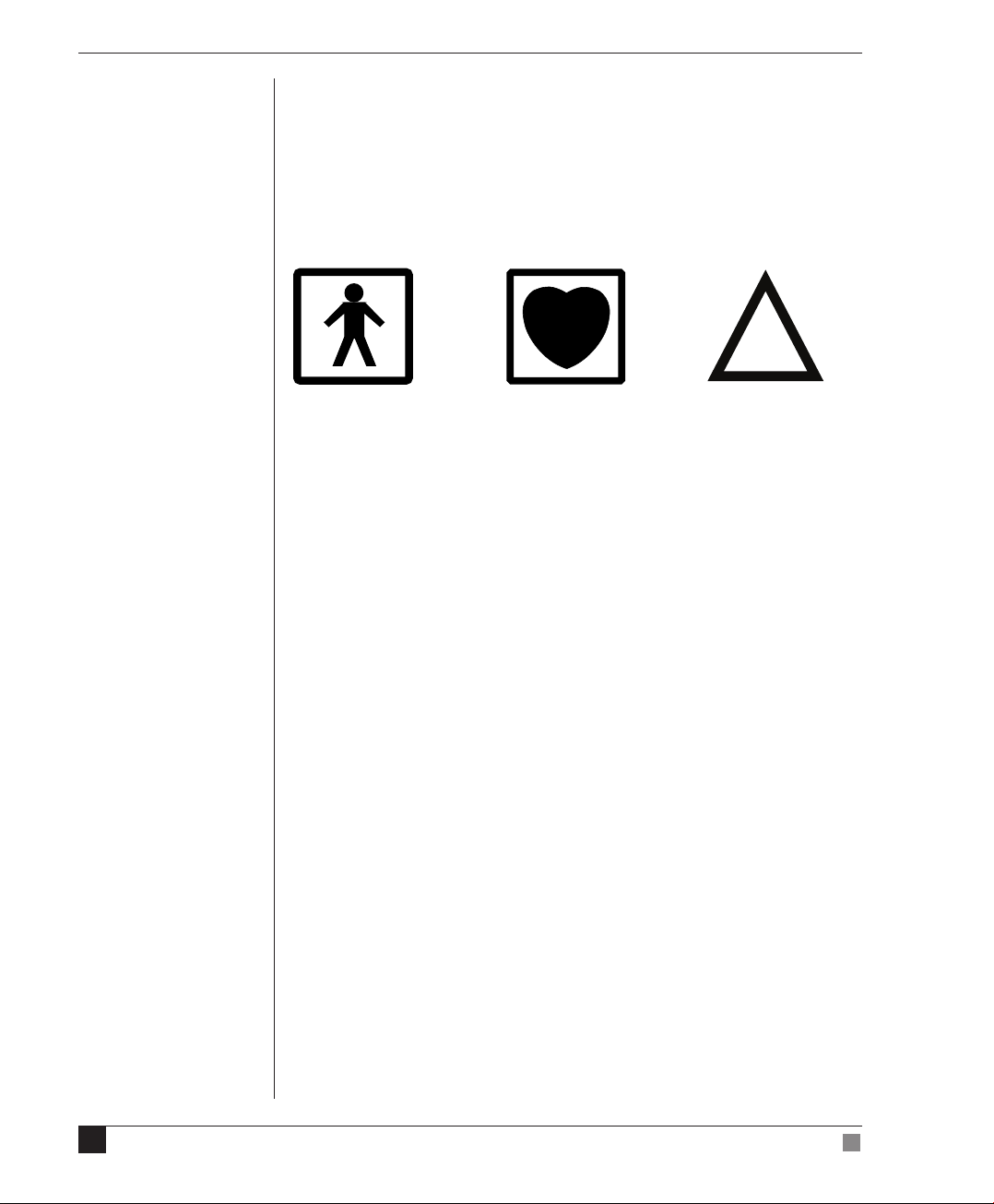
Safety Symbols
Devices manufactured by ADInstruments that are designed for direct
connection to humans are tested to IEC 601-1:1998 (including amendments
1 and 2) and 60601-1-2, and carry one or more of the safety symbols below.
ese symbols appear next to those inputs and output connectors that can be
directly connected to human subjects.
BF symbol: Body-
protected equipment
!
Warning symbol: See
Documentation
CF symbol: Cardiac-
protected equipment
e three symbols are:
•BF (body protected) symbol. is means that the input connectors
are suitable for connection to humans provided there is no direct
electrical connection to the heart.
•CF (cardiac protected) symbol. is means that the input
connectors are suitable for connection to human subjects even when
there is direct electrical connection to the heart.
•Warning symbol. e exclamation mark inside a triangle means
that the supplied documentation must be consulted for operating,
cautionary or safety information before using the device.
Further information is available on request.
Bio Amp Safety Instructions
e Bio Amp inputs displaying any of the safety symbols are electrically
isolated from the mains supply in order to prevent current ow that may
otherwise result in injury to the subject. Several points must be observed for
safe operation of the Bio Amp:
•All Bio Amp front-ends (except for the FE138 Octal Bio Amp) and all
PowerLab units with a built-in Bio Amp are supplied with a 3-lead or
5-lead Bio Amp subject cable and lead wire system. e FE138 Octal
Bio Amp is supplied with unshielded lead wires (1.8m). Bio Amps
are only safe for human connection if used with the supplied subject
cable and lead wires.

7
Safety Notes
•All Bio Amp front-ends and PowerLab units with a built-in Bio Amp
are not debrillator-protected. Using the Bio Amp to record signals
during debrillator discharges may damage the input stages of the
ampliers. is may result in a safety hazard.
•Never use damaged Bio Amp cables or leads. Damaged cables and
leads must always be replaced before any connection to humans is
made.
Isolated Stimulator Safety
Instructions
e Isolated Stimulator outputs from a front-end signal conditioner or
a PowerLab with a built-in isolated stimulator are electrically isolated.
However, they can produce pulses of up to 100 V at up to 20 mA. Injury can
still occur from careless use of these devices. Several points must be observed
for safe operation of the Isolated Stimulator:
•e Isolated Stimulator output must only be used with the supplied
bar stimulus electrode.
•e Isolated Stimulator output must not be used with individual
(physically separate) stimulating electrodes.
•Stimulation must not be applied across the chest or head.
•Do not hold one electrode in each hand.
•Always use a suitable electrode cream or gel and proper skin
preparation to ensure a low-impedance electrode contact. Using
electrodes without electrode cream can result in burns to the skin or
discomfort for the subject.
•Subjects with implantable or external cardiac pacemakers, a cardiac
condition, or a history of epileptic episodes must not be subject to
electrical stimulation.
•Always commence stimulation at the lowest current setting and
slowly increase the current.
•Stop stimulation if the subject experiences pain or discomfort.
•Do not use faulty cables, or those that have exhibited intermittent
faults.
•Do not attempt to measure or record the Isolated Stimulator
waveform while connected to a subject using a PowerLab input or
any other piece of equipment that does not carry the appropriate
safety symbol (see Safety Symbols above).

8Blood FlowMeter Owner’s Guide
Always check the status indicator on the front panel. It will always ash green
each time the stimulator delivers a current pulse. A yellow ash indicates
an ‘out-of-compliance’ (OOC) condition that may be due to poor electrode
contact or electrode cream drying up. Always ensure that there is good
electrode contact at all times. Electrodes that are le on a subject for some
time need to be checked for dry contacts. An electrode impedance meter can
be used for this task.
•Always be alert for any adverse physiological eects in the subject. At
the rst sign of a problem, stimulation must be stopped, either from
the soware or by icking down the safety switch on the front panel
of any built-in Isolated Stimulator or the FE180 Stimulus Isolator.
•e FE180 Stimulus Isolator is supplied with a special transformer
plug pack. e plug pack complies with medical safety requirements.
erefore, under no circumstances should any other transformer be
used with the Stimulus Isolator. For a replacement transformer plug
pack please contact your nearest ADInstruments representative.
General Safety Instructions
To achieve the optimal degree of subject and operator safety, consideration
should be given to the following guidelines when setting up a PowerLab
system either as stand-alone equipment or when using PowerLab equipment
in conjunction with other equipment. Failure to do so may compromise the
inherent safety measures designed into PowerLab equipment.
e following guidelines are based on principles outlined in the international
safety standard IEC60601-1-1: General requirements for safety - Collateral
standard: Safety requirements for medical systems. Reference to this standard
is required when setting up a system for human connection.
PowerLab systems (and many other devices) require the connection of a
personal computer for operation. is personal computer should be certied
as complying with IEC60950 and should be located outside a 1.8 m radius
from the subject (so that the subject cannot touch it while connected to
the system). Within this 1.8 m radius, only equipment complying with
IEC60601-1 should be present. Connecting a system in this way obviates
the provision of additional safety measures and the measurement of leakage
currents.
Accompanying documents for each piece of equipment in the system should
be thoroughly examined prior to connection of the system.

9
Safety Notes
While it is not possible to cover all arrangements of equipment in a system,
some general guidelines for safe use of the equipment are presented below:
•Any electrical equipment which is located within the SUBJECT
AREA should be approved to IEC60601-1.
•Only connect those parts of equipment that are marked as an
APPLIED PART to the subject. APPLIED PARTS may be recognized
by the BF or CF symbols which appear in the Safety Symbols section
of these Safety Notes.
•Only CF-rated APPLIED PARTS must be used for direct cardiac
connection.
•Never connect parts which are marked as an APPLIED PART to
those which are not marked as APPLIED PARTS.
•Do not touch the subject to which the PowerLab (or its peripherals)
is connected at the same time as making contact with parts of the
PowerLab (or its peripherals) that are not intended for contact to the
subject.
•Cleaning and sterilization of equipment should be performed in
accordance with manufacturer’s instructions. e isolation barrier
may be compromised if manufacturer’s cleaning instructions are not
followed.
•e ambient environment (such as the temperature and relative
humidity) of the system should be kept within the manufacturer’s
specied range or the isolation barrier may be compromised.
•e entry of liquids into equipment may also compromise the
isolation barrier. If spillage occurs, the manufacturer of the aected
equipment should be contacted before using the equipment.
•Many electrical systems (particularly those in metal enclosures)
depend upon the presence of a protective earth for electrical safety.
is is generally provided from the power outlet through a power
cord, but may also be supplied as a dedicated safety earth conductor.
Power cords should never be modied so as to remove the earth
connection. e integrity of the protective earth connection between
each piece of equipment and the protective earth should be veried
regularly by qualied personnel.
•Avoid using multiple portable socket-outlets (such as power boards)
where possible as they provide an inherently less safe environment
with respect to electrical hazards. Individual connection of each
piece of equipment to xed mains socket-outlets is the preferred
means of connection.

10 Blood FlowMeter Owner’s Guide
If multiple portable socket outlets are used, they are subject to the following
constraints:
•ey shall not be placed on the oor.
•Additional multiple portable socket outlets or extension cords shall
not be connected to the system.
•ey shall only be used for supplying power to equipment which is
intended to form part of the system.
Cleaning and Sterilization
ADInstruments products may be wiped down with a lint free cloth moistened
with industrial methylated spirit. Refer to the Data Card supplied with
transducers and accessories for specic cleaning and sterilizing instructions.
Preventative Inspection and
Maintenance
PowerLab systems and ADInstruments front-ends are all maintenance-
free and do not require periodic calibration or adjustment to ensure safe
operation. Internal diagnostic soware performs system checks during
power up and will report errors if a signicant problem is found. ere is no
need to open the instrument for inspection or maintenance, and doing so
within the warranty period will void the warranty.
Your PowerLab system can be periodically checked for basic safety by using
an appropriate safety testing device. Tests such as earth leakage, earth
bond, insulation resistance, subject leakage and auxiliary currents and
power cable integrity can all be performed on the PowerLab system without
having to remove the covers. Follow the instructions for the testing device if
performing such tests.
If the PowerLab system is found not to comply with such testing you should
contact your PowerLab representative to arrange for the equipment to be
checked and serviced. Do not attempt to service the device yourself.
11
Safety Notes
Environment
Electronic components are susceptible to corrosive substances and
atmospheres, and must be kept away from laboratory chemicals.
Storage Conditions
•Temperature in the range 0–40 °C
•Non-condensing humidity in the range 0–95%.
Operating Conditions
•Temperature in the range 5–35 °C
•Non-condensing humidity in the range 0–90%.
Disposal
•Forward to recycling center or return to manufacturer.
•Unwanted equipment bearing the Waste Electrical and Electronic
Equipment (WEEE) Directive symbol requires separate waste
collection. For a product labeled with this symbol, either forward
to a recycling center or contact your nearest ADInstruments
representative for methods of disposal at the end of its working life.
WEEE Directive
symbol

12 Blood FlowMeter Owner’s Guide

13
Chapter 1 Introduction
e ADInstruments Blood FlowMeter is one of a family of stand-alone
instruments, designed to measure blood cell perfusion levels in the
microcirculatory beds of skin and other tissues. is Blood FlowMeter
is LabChart compatible (LCC), which means it can be used directly with
LabChart acquisition and analysis soware, in addition to an analog
recording via a PowerLab data acquisition unit.
is owner’s guide covers the features of the Blood FlowMeter, its
operation, maintainence and safety information.
1
CHAPTER
1
1Introduction

14 Blood FlowMeter Owner’s Guide
How to Use This Guide
is owner’s guide describes how to set up and begin using your Blood
FlowMeter. Topics discussed included how to connect the hardware,
perform a simple power-up test and calibration of the Blood FlowMeter. e
appendices provide technical information about the Blood FlowMeter and
look at some potential problems and their solutions. ere is an index at the
end of this guide.
Checking the Blood FlowMeter
Before connecting the Blood FlowMeter to anything, check it carefully for
signs of physical damage.
1. Check that there are no obvious signs of damage to the outside of the
Blood FlowMeter casing.
2. Check that there is no obvious sign of internal damage, such as
rattling. Pick up the Blood FlowMeter, tilt it gently from side to side,
and listen for anything that appears to be loose.
If you have found a problem, contact your authorized ADInstruments
representative immediately, and describe the problem so arrangements can
be made to replace or repair the unit.
The Blood FlowMeter
e remainder of this chapter contains general information about the
features, connections, and indicators of the Blood FlowMeter. More detailed
information can be found in Appendix C.
The Front Panel
Figure 1–1
Front panel of the
BloodFlowMeter
Power and probe status indicators Probe input connector

15
Chapter 1 Introduction
Power Indicator
e power indicator is located at the bottom le of the front panel. When
lit, it indicates that the Blood FlowMeter has power from the external power
supply.
Probe Status Indicator
e probe input has an associated Status indicator. is indicator is used to
indicate what is happening to the channel at any given time. Flash and color
indications are listed below:
•Green (continuous): Channel OK — no probe connected
•Red/Amber (ashing): Calibration in progress
•Amber (continuous): Probe connected and laser operating
Probe Input Connector
e Blood FlowMeter is a single channel device and provides one probe input
connector. e input connector is a polarized (keyed) multi-pin connector
with optical interfaces for the ber optics in the probe cable. e probes are
designed to push and click into the connector. Do not touch or tamper with
any part of the connector as it may damage the optics or internal circuitry.
The Back Panel
Probe Calibration Button
e Blood FlowMeter is designed to automatically congure and calibrate
itself for specic probes. is operation requires a MLA191 Calibration Kit,
which includes a controlled concentration of latex spheres in suspension.
is is discussed in Probe Calibration, page 21.
Probe calibration
button
Figure 1–2
The back panel of the
BloodFlowMeter
Made in England by Oxford Optronix Ltd for ADInstruments Pty Ltd.
DC Power
CLASS 1 LASER Product.
Complies with 21 CFR 1040.10 & 1040.11
Do not obstruct fan inlet.
To be used only with
ML194 External Power Supply.
On
Output
BSC
Output
LDFCalibrate
Signal output
connectors
Power switch and
DC power connector
Fan outlet
USB
16 Blood FlowMeter Owner’s Guide
USB Port (LCC/Digital)
e Blood FlowMeter has a USB port, which connects to a computer with
USB ports or a PCI USB card installed, allowing high data transfer rates with
LabChart soware. Your Blood FlowMeter is supplied with a high-speed USB
cable. For proper use and reliable results, the Blood FlowMeter needs a high-
speed USB connection. In practical terms this means cables between any USB
devices must be no more than 5 meters (16 feet) in length. If you replace the
USB cable, buy a high-speed cable (fully shielded, twisted-pair and standard
USB connections: a narrow rectangular plug at one end and a square plug
with a bevelled top at the other).
Signal Output Connectors (Analog)
ere are two BNC output connectors on the back panel. All signals are
analog and are designed to be suitable for connection to a variety of data
recording systems, particularly PowerLabs.
e signal from the Output BSC represents the percentage backscatter (tissue
remittance). It has a range of 0–5 V (1% remittance is 50 mV).
e Output LDF provides the laser Doppler owmetry output signal, in
the range 0–5 V. is signal represents the relative Blood Perfusion with
1perfusion unit equalling 1 mV.
Fan Outlet
In order to maintain the internal laser diode temperature, the Blood
FlowMeter utilizes a thermostatically controlled fan to supplement cooling
when required. e fan outlet must remain clear of obstructions during
operation.
DC Power Connector
Power to the Blood FlowMeter comes from an external, medically rated,
power supply (provided with the Blood FlowMeter). e power supply unit
is designed to connect to a wide variety of AC supplies. Connection of power
to the Blood FlowMeter is via a mini DIN connector. All power at this point
is low voltage.
Warning
The Blood FlowMeter’s
medical rating is only
valid when used in
conjunction with the
power supply provided.
Using any other type of
supply will not guarantee
medical approval.
USB icon and port
17
Chapter 2 Setting Up
is chapter guides you through connecting your Blood FlowMeter and
subsequent operation of the instrument. e Blood FlowMeter may either
interface directly to LabChart soware (digital) and/or to a PowerLab
data acquisition unit (analog). Direct interfacing to LabChart requires
installation of both ADInstruments LabChart and Blood FlowMeter
Device Enabler soware rst. You should read this chapter carefully before
using your Blood FlowMeter.
Install ADInstruments Software
Please follow the instructions below in the correct order.
First, install ADInstruments LabChart soware
You should rst install the appropriate LabChart version for Windows or
Macintosh on your computer. Place the LabChart CD in the CD drive of
your computer. e installer should auto-run. If it doesn’t, see the Read Me
on the CD. Follow the onscreen instructions.
Next, install the Blood FlowMeter Device Enabler
e Blood FlowMeter Device Enabler is a soware add-on for LabChart
soware.
Place the CD for the ADInstruments Blood FlowMeter Device Enabler in
the CD drive of your computer. e installer should auto-run. Follow the
on-screen instructions. Alternatively, download the Device Enabler via
LabChart Feature Manager or ADInstruments website.
2
CHAPTER
2
2Setting Up
GLP Client
LabChart®Installers
Blood FlowMeter
Device Enabler
6378-A

18 Blood FlowMeter Owner’s Guide
Connecting the Blood FlowMeter
Before connecting anything make sure that the power outlet and the switch
on the rear panel of the Blood FlowMeter are turned o.
Connect the power supply output of the external supply to the power input of
the Blood FlowMeter. Make sure that this connector is pushed all the way in,
as it does not have a locking facility.
USB Connection (Digital)
When you have installed the soware, connect the Blood FlowMeter to your
PC or laptop using the USB cable supplied with the device.
Note: Windows may display a message to indicate that the device driver is
being installed when the Blood FlowMeter is turned on.
BNC Connection (Analog)
Connect the BNC outputs of the Blood FlowMeter to the signal inputs of
your recording device. Note that the Blood FlowMeter has outputs for both
LDF and BSC signals (see Signal Output Connectors, page 16). Both signal
outputs do not need to be used. You only need to connect the output signal
that you wish to record.
USB icons Blood FlowMeter
Computer or
hub connection
USB cable
Figure 2–1
Connecting a Blood
FlowMeter to a computer
with USB

19
Chapter 2 Setting Up
Switching on the Blood FlowMeter
When the power has been connected, turn on the power switch on the rear
panel of the Blood FlowMeter. e Power indicator on the front of the Blood
FlowMeter should glow green and you should hear a double beep from the
unit to indicate that it has initialized.
Connecting the Laser Doppler Probe
Very carefully remove the probe from its protective case and check that the
probe connector is clean and free from dust. To connect the probe to the
probe connector on the front of the Blood FlowMeter, orientate the plug with
respect to the socket until it is aligned correctly. e socket is designed to
only accept the plug in one particular orientation. Once aligned, carefully
push the plug into the socket until locked in position.
If everything is OK then the status indicator for the probe will glow amber.
If there is something wrong with the probe or connection then the status
indicator will remain green.
Wait at least ten minutes before making any measurements to allow the
instrument’s temperature to stabilize. Please note that temperature ‘out-of-
range’ beeps may occur during the warm-up period.
20 Blood FlowMeter Owner’s Guide
Probe Application
Warning: Needle (implantable) laser Doppler probes are ONLY for use in
animals. Only surface laser Doppler probes are safe for use on humans.
Surface probes can be attached to tissue using a self adhesive ring. ese have
adhesive on both sides with a small hole in the center. Needle probes can be
secured by using a micro-manipulator or some similar device.
It is important to control the relative movements of the tissue (especially that
induced by breathing) with respect to the probe. Relative movements will
produce artifacts in the perfusion signal. ese can be reduced by allowing
the supported probe to lightly contact the surface of the tissue. Under some
conditions it may be desirable for the probe to be held in position by hand.
It is essential to ensure that the pressure on the tissue is minimal, otherwise
local occlusion of the microvasculature may result.
Excessive ambient lighting at the probe site can disturb the blood perfusion
reading. Avoid direct illumination of the measurement site, especially
direct sunlight. If erroneous readings of the measurement site from external
lighting levels are suspected, cover the attached probe and measurement area
with a light piece of opaque material.
Probe signal outputs for dierent conditions are listed in Table 2–1.
Condition LDF Backscatter
No probe -2.5 V (-2500 BPU) 0 V (0 %)
Unrecognized probe -5 V (-5000 BPU) -5 V (-100 %)
Low backscatter 0 V (0 BPU) -2.5 V (-50 %)
Flow over range +5 V (+5000 BPU) + 5 V (+100 %)
Temperature Warning
If the internal temperature of the Blood FlowMeter moves outside the
operating temperature range of the device, then it will emit a double beep
every 16 seconds. If this occurs, the instruments should be moved to a cooler
environment for proper operation.
With the temperature out of range, output signals will continue to be
generated but may no longer be within the calibrated tolerance of the system
and should be interpreted with caution. If there are any problems or faults
please contact your ADInstruments representative for further advice.
Table 2–1
Probe outputs for
different conditions
Table of contents
Other ADInstruments Medical Equipment manuals


Popular Medical Equipment manuals by other brands

Beka Hospitec
Beka Hospitec EVE! operating manual

Acrel
Acrel AITR Series Installation and operation manual

Belmont Medical Technologies
Belmont Medical Technologies CritiCool user manual

Schiller
Schiller CARDIOVIT AT-1 Service handbook

Instramed
Instramed I.ON Pro user manual

Halyard
Halyard FLUIDSHIELD 3 N95 Directions for use

Atos Medical
Atos Medical Provox FreeHands FlexiVoice Instructions for use

OAKWORKS
OAKWORKS ProLuxe Series Instruction & maintenance manual

Bodypoint
Bodypoint EVOFLEX EB205 Installation and user instructions

Siemens
Siemens MAGNETOM syngo MR D11 Operator's manual

Beurer
Beurer IH 60 Instructions for use

ProMedTek
ProMedTek Replexa+ instruction manual


