Acrel AITR Series User manual

163
Medical IT System Insulation Monitoring Devices
(Four-Piece Set)
Installation and Operation Manual V2.5
Acrel Co., Ltd.

Declaration
Please read this manual carefully before using this series of products, in which
the involved pictures, logos, symbols, etc. are all reserved by the Acrel Electric Co.,
Ltd. Personnel not inside the company shall not publicly reprint all or part of the
contents without written authorization.
Before using the IT system which is made up of this series of products, please read
the tips and precautions in this operation manual, and Acrel does not take responsibility
for personal injuries or economic losses caused by ignoring tips of this manual;
Transformers and related insulation monitors are professional electrical equipment,
and any relevant operation needs to be carried out by specialized electrical technicians.
Acrel does not take responsibility for personal injuries or economic losses caused by
improper operations of non-professionals.
The contents of the manual will be continuously updated and revised, thus the products
functions in this manual may inevitably have a slight discrepancy with the real objects
during the continuous upgrading process. Users should give first place to the purchased
real products, and can search www. acrel.cn to downloads or through sales channels to
obtain the latest version of the manual.

更改履历
Number
of times
Revision
date
Versions after
revision
Reasons for revision
01
2016.1.20
V2.0
On the basis of the original insulation monitoring
products, the contents of all five pieces of
products are integrated to replace the
instructions of each sub-product.
02
2016.10.25
V2.1
Some errors have been fixed
03
2016.11.7
V2.2
The overview added "products conform to Enterprise
standards Q31/0114000129C013-2016
IT System
Insulation Monitoring Instrument
04
2020.4.29
V2.3
Delete some discontinued accessories;
Add the installation dimension of AID10 cabinet
door
05
2020.6.11
V2.4
Add AID150 cabinet door installation diagram
06
2020.8.14
V2.5
Correct errors and omissions, adjust the wording
Note:

Contents
1 Introduction........................................................................................................................... 1
2 Function features................................................................................................................. 2
2.1 Function features of AITR series medical isolation transformer.........................2
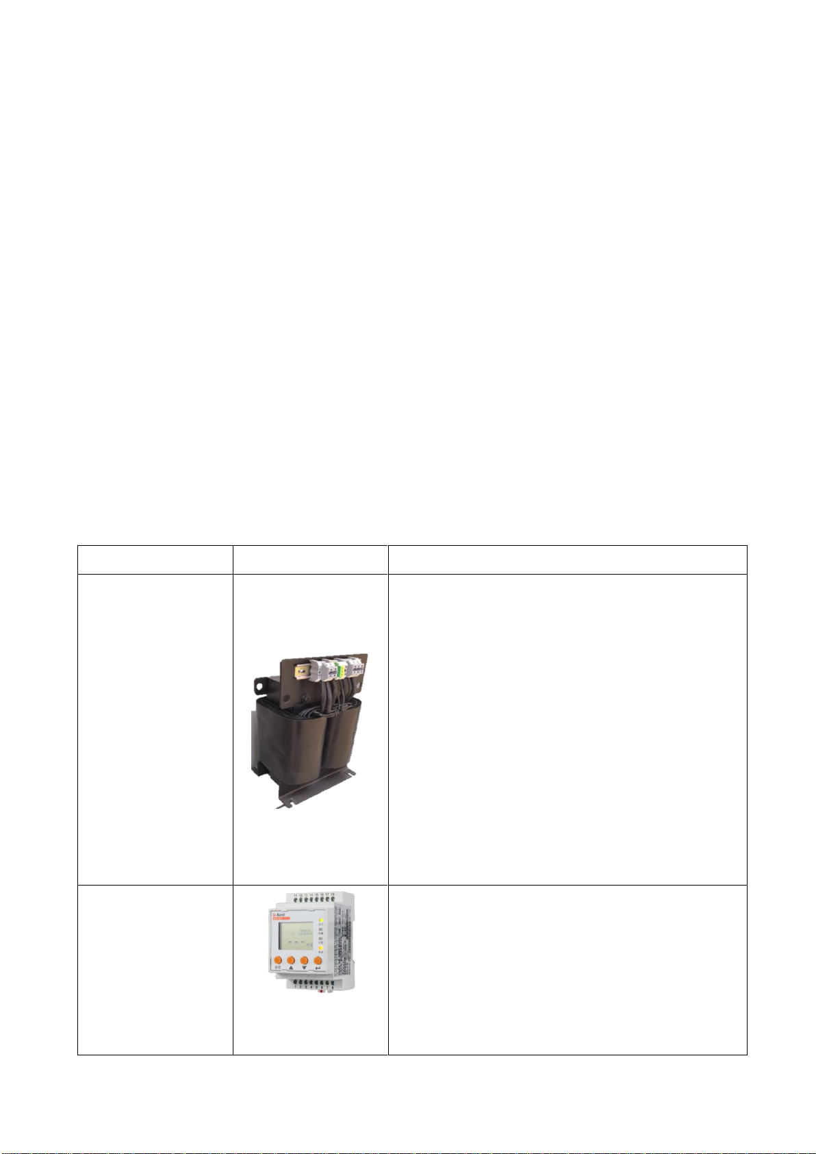
2.2 AIM-M10 medical intelligent insulation monitor.........................................................2
2.3 Function features of AID10/150.......................................................................................3
2.5 Function features of AKH-0.66P26 current transformer...........................................3
3. Reference standard............................................................................................................. 3
4 Technical parameters........................................................................................................... 4
4.1 Technical parameters of AITR series medical isolation transformer.................4
4.2 Technical parameters of AIM-M10 medical insulation monitor...............................5
4.3 Technical parameters of AID10/AID150...........................................................................6
4.4Technical parameters of AKH-0.66P26 current transformer.......................................6
5 Installation and wiring..................................................................................................... 7
5.1 Shape and mounting hole size...........................................................................................7
5.2 Wiring method..........................................................................................................................9
5.3 Installation method...........................................................................................................11
5.4 Typical wiring diagram .............................................................................................................14
5.5 Considerations.....................................................................................................................15
6 Programming and application............................................................................................ 16
6.1 Panel description of AIM-M10..........................................................................................16
6.2 LED indicator instructions.............................................................................................16
6.3 Button function descriptions..........................................................................................17
6.4 Button operation descriptions.......................................................................................18
7 Communication protocol..................................................................................................... 23
7.1 Modbus-RTU communication protocol...............................................................................23
7.2 Introduction to the function code...............................................................................23
7.3 AIM-M10 parameter address table....................................................................................25
8 Typical applications......................................................................................................... 26

8.1 Application of four-piece set of medical IT system insulation monitoring
products in operating room.....................................................................................................26
9 Power on and debugging instructions........................................................................... 27
9.1 Wiring check.........................................................................................................................27
9.2 Common faults and eliminations.....................................................................................28
9.3 Settings and debugging.....................................................................................................29

Medical IT System Insulation Monitoring Devices
1 Introduction
Medical IT systems are primarily used in critical medical 2 locations such as operating rooms,
ICU/CCU intensive care units to provide safe, reliable, and continuous distribution of critical
equipment in these locations. Medical insulation monitoring products are developed by Ankore
Electric according to the special requirements of insulation resistance of distribution system in
medical 2 type places with many years of design experience in the power meter industry. It can be
used for isolating power system in various operating rooms and intensive care units in medical places,
realizing real-time monitoring of system insulation, load, isolation transformer temperature and
other operating conditions, as well as remote monitoring. Products comply with the enterprise
standard Q31/0114000129C013-2016
IT System Insulation Monitor
provisions.
Insulation monitoring products of medical IT system (four-piece set) include AITR series medical
isolation transformer, AIM-M10 medical intelligent insulation monitor, AKH-0.66P26 current
transformer and AID series (AID10, AID150) external alarm and display instrument, etc., as shown
in Table 1.
Table 1 Medical IT System Insulation Monitoring Products
Type
Picture
Description
AITR series medical
isolation
transformer
AITR series isolation transformer is specially
used in medical IT system. The windings are treated
with double insulation and have electrostatic
shielding layer, which reduces electromagnetic
interference between windings. The PT100
temperature sensor is installed in the wire bag to
monitor the temperature of transformer. The whole
body is treated with vacuum invasion paint, which
increases mechanical strength and corrosion
resistance. The product has good temperature rise
performance and very low noise.
AIM-M10 medical
intelligent
insulation monitor
The AIM-M10 medical intelligent insulation monitor
is compact in size, easy to install, intelligent,
digital and networked, and is an ideal choice for
insulation monitoring of isolation power supply
systems in operating rooms, intensive care units
and other medical places.

AKH-0.66P26 current
transformer
The AKH-0.66P26 type current transformer is the
protective current transformer supporting the
AIM-M10 insulation monitor, of which the maximum
measurable current is 60A and the transformation
ratio is 2000:1. The current transformer is
directly fixed inside cabinet by screwing, and the
secondary side is leaded out by the terminal, which
is convenient to install and use.
AID series
external
alarm and
display
instrument
AID10
It is suitable for wall installation embedded in
operating room or nurse station and can monitor 1
AIM-M10 insulation monitor. It has sound and light
alarm function of insulation, overload,
overtemperature and equipment failure, and RS485
communication
AID150
LCD display, RS485 bus, centralized monitoring of
up to 16 SETS of AIM-M10 medical intelligent
insulation monitor data, sound and light alarm can
be remote. The AID150 can also monitor data from
multiple AIM-R100 residual current monitors.
2 Function features
2.1 Function features of AITR series medical isolation transformer
The transformation ratio between the primary and secondary windings is 1:1.
Double insulation treatment is adopted between the windings, and the electrostatic
shielding layer is designed.
The PT100 temperature sensor is installed in each wire packet to monitor the temperature
of the isolation transformer.
Used for the transformation of TN system into IT system (ungrounded system) after isolation
transformer.
2.2 AIM-M10 medical intelligent insulation monitor
Real time monitoring of IT system to ground insulation resistance, transformer load current,
transformer winding temperature, and give alarm indication when fault occurs;
The real-time monitoring system wire break fault, temperature sensor wire break fault and
function ground wire break fault, and give alarm indication when the fault occurs;
Relay output, LED indicator and other fault indication;

MODBUS-RTU, which communicates with external alarm and display instrument, can monitor the
operation of IT system remotely;
Event record, including the time and type of the alarm, is convenient for the operator to analyze
the operation status of the system and eliminate the fault in time;
DC24 V power output function can provide instrument power for external alarm and display
instrument.
2.3 Function features of AID10/150
The insulation resistance alarm value, load current alarm value and transformer temperature
alarm value of the system can be set remotely.
When the system appears insulation fault, overload, transformer temperature over limit and
wiring fault, alarm and display instrument gives out the corresponding sound and light alarm,
and has the function of eliminating sound alarm.
Using advanced fieldbus technology, the remote monitoring function can be realized by real-time
data interaction with the insulation monitor.
Table 2 Functional Description of AID Series Products
Model
Selection Description
AID10
It can monitor one set of AIM-M10 insulation monitor and be used for installation by
embedding into wall.
AID150
It can monitor 16 sets of AIM-M10 insulation monitoring instruments to the maximum
and AIM-R100 residual current monitor which can be used for installation by embedding
into wall. It is fit for the centralized monitoring on operating room or ICU or other
medical sites.
2.5 Function features of AKH-0.66P26 current transformer
The maximum measurable current is 60A, and the transformation change ratio is 2000:1.
Work with the AIM-M10 insulation monitoring instrument to measure the load current of isolation
transformer.
3. Reference standard
◆IEC 60364-7-710: 2002
Building electrical installations section 7-710: Requirements for special
installations or locations----medical locations
;
◆IEC 61557-8-2014
Electrical safety of low voltage distribution system below AC 1000V and DC
1500V, Test, measurement or monitoring equipment for protection test section 8: Insulation
monitoring device for IT systems
;
◆IEC 61557-9-2014
Electrical safety of low voltage distribution system below AC 1000V and DC

1500V, Test, measurement or monitoring equipment for protection test section 9: insulation fault
positioning equipment for IT systems
;
◆JGJ 16-2008
Code for electrical design of civil buildings
;
◆IEC61558-1: 2009
Safety of power transformers, power supplies, reactors and similar products
section 1: General requirements and tests
;
◆IEC61558-2-15: 2011
Safety of power transformers, power supplies and similar products section
16:
Special requirements for isolation transformers for power supply in medical locations
.
4 Technical parameters
4.1 Technical parameters of AITR series medical isolation transformer
Refer to Table 3.
Table 3 Technical Parameters of AITR Series of Medical Isolation Transformer
Type
AITR10000
AITR8000
AITR6300
AITR5000
AITR3150
Insulation
class
H
H
H
H
H
Protection
class
IP00
IP00
IP00
IP00
IP00
Power / voltage
/ current
Rated power
10000VA
8000VA
6300VA
5000VA
3150VA
Rated frequency
50-60Hz
50-60Hz
50-60Hz
50-60Hz
50-60Hz
Rated input
voltage
AC230V
AC230V
AC230V
AC230V
AC230V
Rated input
current
45.3A
36A
28.5A
22.5
14.2A
Rated output
voltage
AC230V/115V
AC230V/115V
AC230V/115V
AC230V/115V
AC230V/115V
Rated output
current
43.5A
34.7A
27.4A
21.7
13.7A
Inrush current
<12In
<12In
<12In
<12In
<12In
Leakage current
<200μA
<200μA
<200μA
<200μA
<200μA
No load input
current
1.359A
1.08A
0.855A
0.675A
0.426A
No load output
voltage
235V±3%
235V±3%
235V±3%
235V±3%
235V±3%
Short circuit
voltage
<6.9V
<6.9V
<6.9V
<6.9V
<7.5V
General

parameters
Fuse wire
80A
63A
50A
35A
25A
Primary winding
resistance
<55mΩ
<64mΩ
<80mΩ
<131 mΩ
<245mΩ
Secondary
winding
resistance
<45mΩ
<64mΩ
<80mΩ
<116 mΩ
<228mΩ
Iron loss
<150W
<105W
<107W
<77W
<55W
Copper loss
<230W
<200W
<170W
<125W
<120W
Efficiency
>96%
>96%
>96%
>96%
>95%
Maximum ambient
temperature
<40℃
<40℃
<40℃
<40℃
<40℃
No-load
temperature
rise
<36℃
<33℃
<31℃
<26℃
<22℃
Full load
temperature
rise
<65℃
<76℃
<67℃
<62℃
<55℃
Noise grade
<40dB
<40dB
<40dB
<40dB
<40dB
4.2 Technical parameters of AIM-M10 medical insulation monitor
Refer to Table 4.
Table 4 Technical parameters of AIM-M10 insulation monitoring instrument
Auxiliary
power supply
Voltage
AC220V
(±10%)
Temperature
measurement
Thermistor
PT100
Frequency
50/60Hz
Measuring range
-50—+200℃
Power
consumption
<5W
Alarm value range
0—+200℃
Insulation
monitoring
Measuring
range of
insulation
resistance
10-999kΩ
Alarm output
Output mode
1 relay output
Absolute
percentage
error
0—±10%
Contact capacity
AC 250V/3A DC
30V/3A
Alarm value
50—999kΩ
Environment
Operating
-10—+55℃

temperature
Response
time
<2s
Storage temperature
-20—+70℃
Measuring
voltage
<12V
Relative humidity
5%-95%,
non-condensate
Measuring
current
<42uA
Altitude
≤2500m
Load current
Measuring
range
2.1-50A
Communication
RS485 interface,
Modbus-RTU
Alarm value
5-50A
Rated impulse voltage/pollution
degree
4KV/Ⅲ
Measuring
accuracy
≤±5%
EMC/EMR
Conform to IEC
61326-2-4
4.3 Technical parameters of AID10/AID150
Refer to Table 5.
Table 5 Technical parameters of AID120/150
Parameter Type
AID10
AID150
Auxiliary power
supply
Voltage
DC 24V
Consumption
< 0.6W
Insulation alarming range
——
14A、18A、22A、28A、35A、45A
Temperature alarm setting range
——
0~+200℃
Number of monitored systems
1
16
Alarm method
Sound-light alarm
Alarm type
Insulation failure, overload, overheat, equipment failure
Communication mode
RS485,MODBUS-RTU
Display mode
LED display
128×64 LCD display
4.4Technical parameters of AKH-0.66P26 current transformer
Refer to Table 6.
Table 6 Technical Parameters of AKH-0.66P26 Current Transformer
Input current
0.5mA~50A
Frequency
range
0.02-10 kHZ
Output current
0.025~25 mA
Loading
resistance
<200Ω

Temperature
coefficient
100 ppm/℃
Transient
current (1s)
200A
Phase displacement
10
Installation
Fixed with 4×10 screws
Operating
temperature
-35~+70℃
Secondary
wiring
Single core >0.75mm2, Maximum
length of 1 meter
Storage temperature
-40~+75℃
Single core twisted pair, 0.75mm2,
Maximum length of 10 meters
Secondary
resistance range
95~120Ω
Isolation
pressure
5000Vac
Accuracy
0.5%
Linearity
0.5%
5 Installation and wiring
5.1 Shape and mounting hole size
5.1.1 External dimensions of AITR series medical isolation transformer (unit: mm)
Shape structure and size of AITR series medical isolation transformer are shown as below and in
Table 7 (unit: mm)
External dimensions of AITR series medical isolation transformer
Table 7 External Dimensions of AITR Series Medical Isolation Transformer
Type
Capacity (VA)
A(mm)
B(mm)
C(mm)
D(mm)
E(mm)
F(mm)
Total weight (kg)
(mm) (mm)
(kg)
AITR10000
10000
280
275
427
240
190
φ11
92
AITR8000
8000
280
265
427
240
190
φ11
90
AITR6300
6300
280
255
427
240
175
φ11
75
AITR5000
5000
280
255
427
240
175
φ11
73
AITR3150
3150
280
225
427
240
175
φ11
53
5.1.2 External dimensions of AIM-M10 medical insulation monitor (unit: mm)

Acrel
AIM-M10
On
Insulation
Overload
Overtemp
Test
Acrel
AIM-M10
Front view Side view Bottom view
5.1.3 External dimensions of AID series(unit: mm)
On Overload
Insulation Overtemp
Test
AID10
Mute
AID10 front view AID10 hole size AID10 side view
Test
Mute
Menu
Acrel
On Comm
AID150
AID150 front view AID150 hole size AID150 side view
5.1.5 External dimensions of AKH-0.66P26 current transformer (unit: mm)

φ2.3
I
Front view Bottom view
5.2 Wiring method
5.2.1 Wiring mode of AITR series medical isolation transformer
The input terminals at the transformer terminal blocks are labeled with “PM”, in which two
terminals 0 and 230 are connected to the input 220V single-phase AC. The output terminals are labeled
with “SEC”, in which the output voltage of two terminals 0 and 230 is AC 220V and is connected
to external field load. The S terminal is connected to the PE bus bar on the spot (or the equipotential
terminal line). Two ST terminals are temperature sensor interfaces, which are respectively connected
to the No.17 and 18 terminals of AIM-M10 insulation monitoring instrument.
Figure 2 AITR series medical isolation transformer terminal blocks diagram
Note: The wirings of input and output terminals of the isolation transformer should select the copper
wires matching the line diameter based on the isolation transformer rated input and output current
(refer to tables in section 5.4). S terminal wiring can select 2×4mm2yellow-green wire. The wiring
of two ST terminals can select 2×1.5mm2shielded twisted pairs, and the wiring should not be too
long.
5.2.2 Wiring mode of AIM-M10
Lower row terminals:
FE, KE (1,2) are connected to the field equipotential grounding terminal block as instrument
functional grounding.
A, B (3,4) are communication terminals connected with external alarm and display instrument.
+24V, 0V (5,6) are DC power output to supply power for alarm and display instrument.

J1, J2 (7,8) are output of over temperature alarm relay (used to control cooling fan).
Upper terminal:
L1, L2 (11, 12) are connected with monitored it system.
I0, I1 (15, 16) are signal input of current transformer akh-0.66p26.
T0, T1 (17, 18) are signal input of temperature sensor.
Note:
1)
为用于CT二次侧短接的试验端子
注
:
is used for the test terminals of CT secondary side short connection.
2)The wirings connecting the No.11 and 12 terminals of the insulation monitor can select 2×1.5mm2
copper wires, and the FE and KE terminals corresponding to the No.1 and 2 can select 2×4mm2
yellow-green wires (grounding wires). J1, J2 relay output are the dry nodes, which need additional
power supply during the control of external load. For example, J1 controls AC 220V cooling fan,
then the AC 220V power supply is needed, and the wiring line type should be determined according
to the load current.
3) 2×1.5mm2shielded twisted pair cable can be selected for current transformer signal line
corresponding to terminals 15 and 16, temperature signal line corresponding to terminals 17 and
18, RS485 communication line corresponding to terminals 3 and 4. The COM port for communication
does not need wiring.
5.2.3 Wiring mode of AID120/150 centralized alarm and display instrument
A and B are connected with A and B in the lower terminal of AIM-M10. The terminals of the power

supply correspond to the positive pole and ground of the 24V DC power module respectively. The wiring
diagram is shown in the following figure.
RS485 communication Auxiliary power supply
The 24V power supply can be connected by multiple copper wires of 2 x 1.5mm2, and the RS485
communication terminal can be connected by shielded twisted pair of 2 x 1.5mm2.
5.3 Installation method
In addition to the AID series external alarm and display instrument, the five-piece insulation
monitoring products of medical IT system should be centrally installed in the distribution cabinet
(isolated power cabinet). The isolation transformer should be installed at the bottom of the
distribution cabinet, fixed with supporting bolts, and cooling fan should be installed. The
instrument and circuit breaker are mounted on the upper panel. If the isolation transformer is
installed separately, it should not be too far from the AIM-M10 insulation monitor. When the
AID10/150 external alarm and display instrument is used in the operating room, it can be embedded
in the wall and installed next to the information panel in the operating room for the convenience
of manual medical personnel. When AID150 is used in ICU/CCU and other intensive care units, it should
be installed in the hand nurse station for the nurses on duty to check, and the RS485 communication
between each insulation monitoring instrument, AID centralized alarm and display instrument under
centralized monitoring should be connected hand in hand. The external wiring of the AID series
external display device includes two 24V power lines and one RS485 communication line with 2-core
shielded twisted pair. These three lines are drawn from the isolated power cabinet, and pipelines
should be reserved during construction.
5.3.1 Installation mode of AIM-M10 medical insulation monitor
AIM-M10 insulation monitor adopts the installation method of the guide rail, and the fixation mode
is the clip buckle type, as shown in the following figure:

5.3.2 Installation mode of AID series alarm and display instrument
1)If AID10 is embedded into the wall, the standard 86*86 mounting hole shall be reserved in advance.
The installation diagram is as follows:
3)Fix AID10 rear cover
assembly with 86 boxes
M4 Screw
4)Connect AID10 upper shell
assembly with lower shell
assembly (note pin alignment
with socket)
5)Installation is complete
Note: Due to the continuous
updating of our products, this
drawing is for reference only
until it has been confirmed by
the relevant personnel.
Upper shell
assembly Run Overload
Insulation OverTEMP
Test
AID10
Mute
86 boxes
and walls
86 boxes
and walls
86 boxes
and walls
Lower shell
assembly
2)Connect the connecting wire
to the AID10 rear cover
assembly through the terminal
AID10 shape
1)Separate the upper
and lower shell of
AID10 with a screwdriver
2)If AID10 is installed by opening the cabinet door, the installation diagram is as follows:
1.Separate the upper shell
from the lower shell with a
slotted screwdriver
2.Door panel hole size
3.Fix the lower shell
and door panel with
M4 screws
4.Connect the upper shell
and the lower shell
Cabinet
运行 过载
绝缘 超温
消音 自检
AID10
5.Installation is complete
AID10 shape
5.3.3 Installation mode of AID150
1) If you choose to embed the wall for installation, the installation diagram is as follows:

1.Product shape 2.Size of wall
openings
3.Insert the shell
into the wall
5.Fixed LCD board
and Shell
4.Connect to the
LCD board through
the terminal
Attention:
As our products
are constantly
updated, this
drawing is for
reference only
until it has been
confirmed by the
relevant
personnel.
Acrel
Run Comm Error Alarm
AID150
TEST
MENU
During the decoration, firstly the AID150 shell should be embedded in the wall to be fixed and be
close to the knockouts of the pipeline, so that the wires (two power cords + a two-core shielded
twisted pair) can be drawn to the front cover, and then fix the cover on the shell with screws.
2)If the AID150 external alarm and display instrument is installed by opening the cabinet door,
the installation diagram is as follows:
AID150 shape Separate the product
body from the cassette
Install the cassette on
the door panel
Hole size of door
panel
Screw Clasp
Fix the panel to
the cassette
Screw
Attention:
As our products
are constantly
updated, this
drawing is for
reference only
until it has
been confirmed
by the relevant
personnel.

5.4 Typical wiring diagram
Run Overload
Insulation Overtemp
Mute Test
AID10
Note:
1) The connection line diameter of the input and output of the isolation transformer should match
the rated current of the isolation transformer, or it can be selected according to the following
table:
Isolation transformer type
Selected line diameter
AITR3150
3×4mm2
AITR5000/AITR6300
3×6mm2
AITR8000/AITR10000
3×10mm2
2) Terminals 11 and 12 of AIM-M10 insulation monitor need to be connected with AC220V of IT system,
which can be directly connected to 0 and 230V output terminals at the secondary side of isolation
transformer according to the diagram, and connected with 6A fuse protection in series.
3) The relay output control of the No.7 and 8 terminals of the AIM-M10 insulation monitor is a dry
node, which needs an additional fan power supply when used for the fan control. When multiple
transformers are centrally installed in one isolation power cabinet, multiple fans should be
connected in a parallel mode controlled by multiple insulation monitors, that is, every one
insulation monitor can start or stop all fans.
4) AKH-0.66P26 only needs to pass through one of the L1, L2 two wires of the isolation transformer
secondary side output terminal, but can not pass through the two wires simultaneously. The output
is connected with the 2×1.5mm2 wire to the No.15, 16 terminals of AIM-M10, which is not allowed
for grounding.
5) In order to reliably monitor the grounding insulation of the isolation power system, the No.11,

12 terminals of AIM-M10 insulation monitor should be reliably connected to IT system (which can
be connected in parallel to the output terminal of the isolation transformer) with 2×1.5mm2
multicore copper wires, and the No.1, 2 terminals should be respectively connected to the on-site
equipotential terminals (or the grounding terminals in the isolation power cabinet) with two
independent 4mm2yellow-green grounding wires.
6) When AID150 centralized alarm and display instrument monitors multiple sets of AIM-M10 at the
same time, the communication line should be connected by hand (that is, after the communication
line of the previous meter is connected to the communication terminal of this meter, it is led out
from the terminal of this meter and connected to the communication terminal of the following table).
One matching resistance shall be connected between the two communication terminals at the head and
end of RS485 bus, and the resistance recommended and attached with the goods. The resistance is
120Ω. The No.5, 6 Terminals of AIM-M10 correspond to + 24 V and G respectively. It is recommended
to select 0.5 mm2 wire to supply power to alarm and display instrument.
5.5 Considerations
1) Medical IT system insulation monitoring and fault locating seven pieces of products should be
centrally installed in the isolation power cabinet except for AID series. If the field space is
too limited to apply the isolation power cabinet, the isolation transformer can be installed
separately, but should not be too far away from the insulation monitor and the field load.
2) The installation of wiring should strictly follow the wiring diagrams, which should preferably
use the pressure connection with the needle-type fittings, and then insert into the corresponding
terminal of the instrument and tighten the screws to avoid the abnormal work conditions of instrument
caused by loose connection.
3) The grounding wire of the instrument and the transformer shall be reliably connected with the
equipotential terminals in the field. When applying the isolation power cabinet, it should be
connected to the grounding terminals in the isolation power supply cabinet, and then to the
equipotential terminals in the field.
4) The current input of AIM-M10 medical intelligent insulation monitoring instrument should use
a matching AKH-0.66P26 type current transformer. It is recommended to use pressure connection with
U-type indenters during wiring operation, and then connect to the CT terminal. Do not directly use
the bare head connection, for the considerations of reliable connection and easy disassembly. Before
removing the wiring, the CT primary circuits must be cut off or the secondary circuits must be short
connection.
5) Special reminder:
Any isolation transformer will have an impact current when it starts up, and too large impact current
may cause the circuit breaker at primary side of the transformer difficult to disconnect or shut
This manual suits for next models
12
Table of contents
Other Acrel Medical Equipment manuals
Popular Medical Equipment manuals by other brands

Primedic
Primedic Defi-Monitor ECO 1 Instructions for use

Otto Bock
Otto Bock 490E163 Series Instructions for use

Olympus
Olympus ScopeGuide UPD-3 Quick reference guide

medi
medi Genumedi E+motion Instructions for use

DePuy Mitek
DePuy Mitek VAPR Series Instructions for use

Davita
Davita Magneto Fit MF 400 user manual