ADJ ELEMENT HEX User manual

User Manual
ELEMENT HEX
ELEMENT HEX PEARL
User Instructions

2
©2022 ADJ Products, LLC all rights reserved. Information, specications, diagrams, images, and
instructions herein are subject to change without notice. ADJ Products, LLC logo and identifying
product names and numbers herein are trademarks of ADJ Products, LLC. Copyright protection claimed
includes all forms and matters of copyrightable materials and information now allowed by statutory
or judicial law or hereinafter granted. Product names used in this document may be trademarks or
registered trademarks of their respective companies and are hereby acknowledged. All non-ADJ
Products, LLC brands and product names are trademarks or registered trademarks of their respective
companies.
ADJ Products, LLC and all aliated companies hereby disclaim any and all liabilities for property,
equipment, building, and electrical damages, injuries to any persons, and direct or indirect economic
loss associated with the use or reliance of any information contained within this document, and/or as
a result of the improper, unsafe, insucient and negligent assembly, installation, rigging, and operation
of this product.
FCC STATEMENT
This device complies with Part 15 of the FCC Rules. Operation is subject to the following two
conditions: (1) this device may not cause harmful interference, and (2) this device must accept
any interference received, including interference that may cause undesired operation.
FCC RADIO FREQUENCY INTERFERENCE WARNINGS & INSTRUCTIONS
This product has been tested and found to comply with the limits per Part 15 of the FCC Rules.
These limits are designed to provide reasonable protection against harmful interference in a
residential installation. This device uses and can radiate radio frequency energy and, if not
installed and used in accordance with the included instructions, may cause harmful interference
to radio communications. However, there is no guarantee that interference will not occur in
a particular installation. If this device does cause harmful interference to radio or television
reception, which can be determined by turning the device o and on, the user is encouraged to
try to correct the interference by one or more of the following methods:
• Reorient or relocate the device.
• Increase the separation between the device and the receiver.
• Connect the device to an electrical outlet on a circuit dierent from which the radio receiver
is connected.
• Consult the dealer or an experienced radio/TV technician for help.
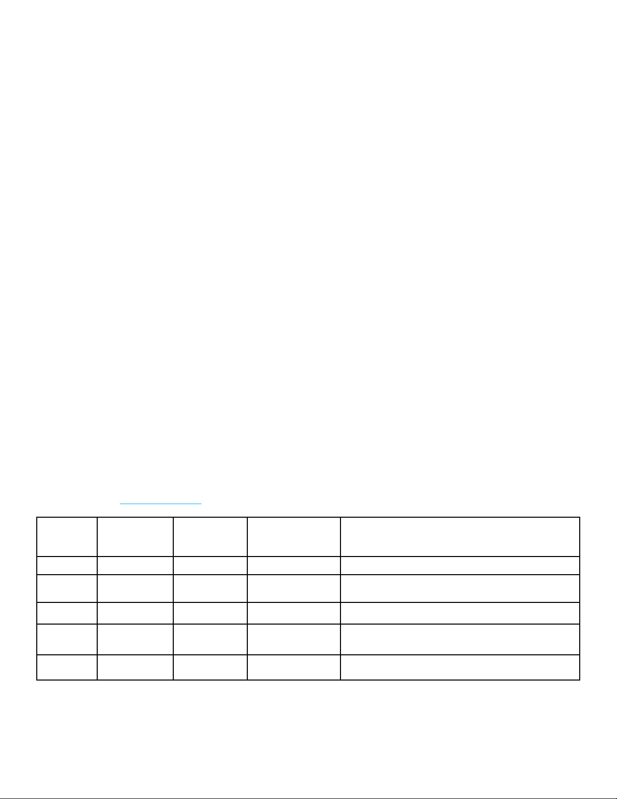
DOCUMENT VERSION
Please check www.adj.com for the latest revision/update of this guide.
Europe Energy Saving Notice
Energy Saving Matters (EuP 2009/125/EC)
Saving electric energy is a key to help protecting the environment. Please turn o all electrical products when
they are not in use. To avoid power consumption in idle mode, disconnect all electrical equipment from power
when not in use. Thank you!
Date Document
Version Software
Version DMX Channel
Mode Notes
09/11/17 1.2 1.01 6/7/8/11/12 ETL Version
11/07/18 1.4 1.06 No Change Display Lock
IR Remote Functions Updated
11/17/20 1.6 1.08 No Change Updated System Menu
09/30/21 1.8 N/C No Change
Updated Dimension Drawings, Specications
02/09/22 2.0 N/C No Change Updated UC IR & Airstream Control

TABLE OF CONTENTS
3
Introduction 4
Features I Warranty Registration I Installation 5
Safety Precautions 6
Battery Precautions I Battery Status & Charging 8
Overview 10
DMX Setup 11
DMX Addressing 13
DMX Modes 15
Color Macro Chart 17
System Menu 18
Operating Instructions 19
Primary-Secondary Set Up I WiFly Set Up 23
UC IR & Airstream Control 24
Dimmer Curve Chart 26
Dimensional Drawings I Kickstand Angles 27
Multiple Unit Power Linking I Fuse Replacement 28
Trouble Shooting I Cleaning I Optional Accessories 28
Warranty 29
Specications 30

4
Unpacking: Thank you for purchasing the Element Hex by ADJ Products, LLC. Every Element Hex &
Element Hex Pearl has been thoroughly tested and has been shipped in perfect operating condition.
Carefully check the shipping carton for damage that may have occurred during shipping. If the carton
appears to be damaged, carefully inspect your xture for any damage and be sure all accessories
necessary to operate the unit has arrived intact. In the case damage has been found or parts are
missing, please contact our toll free customer support number for further instructions. Do not return
this unit to your dealer without rst contacting customer support.
Introduction: The Element Hex & Element Hex Pearl is a rechargeable lithium battery powered, DMX
intelligent, LED PAR xture with ADJ’s WiFly TransCeiver with wireless DMX built-in. WiFly control and
battery power give you the freedom to set up your unit where ever you wish without the restrictions
of power or DMX cabling. This unit can be used in a stand alone mode or connected in a Primary/
Secondary set up. This unit has ve operating modes: Auto mode (color change, color fade, and color
change and fade combination), RGBWA+UV Dimmer mode, Static Color mode, Sound Active mode,
and DMX control mode. To optimize the performance of this product, please read these operating
instructions carefully to familiarize yourself with the basic operations of this unit. These instructions
contain important safety information regarding the use and maintenance of this unit. Please keep this
manual with the unit, for future reference.
Customer Support: Contact ADJ Service for any product related service and support needs. Also
visit forums.adj.com with questions, comments or suggestions.
Parts: To purchase parts online visit http://parts.adj.com
ADJ SERVICE USA - Monday - Friday 8:00am to 4:30pm PST
ADJ SERVICE EUROPE - Monday - Friday 08:30 to 17:00 CET
ADJ PRODUCTS LLC USA
6122 S. Eastern Ave. Los Angeles, CA. 90040 323-582-2650 | Fax
ADJ SUPPLY Europe B.V.
Junostraat 2 6468 EW Kerkrade, The Netherlands
+31 (0)45 546 85 00 | Fax +31 45 546 85 99
ADJ PRODUCTS GROUP Mexico
AV Santa Ana 30 Parque Industrial Lerma, Lerma, Mexico 52000
+52 (728) 282-7070
Warning! To prevent or reduce the risk of electrical shock or re, do not expose this unit to rain or
moisture.
Caution! There are no user serviceable parts inside this unit. Do not attempt any repairs yourself,
doing so will void your manufactures warranty. In the unlikely event your unit may require service
please contact ADJ Products, LLC.
PLEASE recycle the shipping carton when ever possible.
INTRODUCTION

5
•Five Operating Modes
•Electronic Dimming 0-100%
•RGBWA+UV Color Mixing
•5 Selectable Dimming Curves
•63 Color Macros
•Built in Microphone
•DMX-512 protocol
•3-Pin DMX Connection
•5 DMX Channel Modes: 6 Channel Mode, 7 Channel Mode, 8 Channel Mode, 11 Channel Mode, &
12 Channel Mode
•Rechargeable Lithium Battery
•Built-In ADJ’s WiFly TransCeiver Wireless DMX
•ADJ UC IR & Airstream IR compatible
•Multiple Unit Power Linking (See page 26)
Incuded Accessories:
1 x I.E.C. power cable
1 x UC IR Remote Control
1 x Airstream IR Transmitter
The Element Hex carries a 2 year limited warranty. Please ll out the enclosed warranty card to validate
your purchase. All returned service items whether under warranty or not, must be freight pre-paid
and accompany a return authorization (R.A.) number. The R.A. number must be clearly written on the
outside of the return package. A brief description of the problem as well as the R.A. number must also
be written down on a piece of paper included in the shipping carton. If the unit is under warranty, you
must provide a copy of your proof of purchase invoice. You may obtain a R.A. number by contacting
our customer support team on our customer support number. All packages returned to the service
department not displaying a R.A. number on the outside of the package will be returned to the shipper.
The unit should be mounted using a mounting clamp (not provided), axing it to the mounting bracket
that is provided with the unit. Always ensure that the unit is rmly xed to avoid vibration and slipping
while operating. Always ensure that the structure to which you are attaching the unit is secure and is
able to support a weight of 10 times the unit’s weight. ALWAYS use safety cables that can hold 12
times the weight of the unit when installing the xture.
This equipment must be installed by a professional, and it must be installed in a place where it is out
of the reach of people’s grasp.
FEATURES
WARRANTY REGISTRATION
INSTALLATION

6
NOT FOR RESIDENTIAL/HOUSE HOLD USE
NON DESTINÉ À UN USAGE DOMESTIQUE
SUITABLE FOR DAMP LOCATIONS
CONVIENT AUX EMPLACEMENTS HUMIDES
•To reduce the risk of electrical shock or re, do not expose this unit rain or moisture.
•Do not attempt to operate this unit if the power cord has been frayed or broken. Do not attempt to
remove or break o the ground prong from the electrical cord. This prong is used to reduce the risk
of electrical shock and re in case of an internal short.
•Disconnect from main power before making any type of connection.
•Do not remove the cover under any conditions. There are no user serviceable parts inside.
•Never operate this unit when it’s housing is removed.
•Never plug this unit in to a dimmer pack.
•Always be sure to mount this unit in an area that will allow proper ventilation. Allow about 6” (15cm)
between this device and a wall.
•Do not attempt to operate this unit, if it becomes damaged.
•During long periods of non-use, disconnect the unit’s main power. Always mount this unit in safe and
stable matter.
•Power supply cords should be routed so that they are not likely to be walked on or pinched by items
placed upon or against them, paying particular attention to the point they exit from the unit.
•Cleaning -The xture should be cleaned only as recommended by the manufacturer. See page 35
for cleaning details.
•Heat -The appliance should be situated away from heat sources such as radiators, heat registers,
stoves, or other appliances (including ampliers) that produce heat.
•The xture should be serviced by qualied service personnel when:
A. The power-supply cord or the plug has been damaged.
B. The appliance does not appear to operate normally or exhibits a marked change in performance.
C.The xture has fallen and/or subjected to extreme handling.
SAFETY PRECAUTIONS

SAFETY PRECAUTIONS
7
RISK GROUP 3 - RISK OF EXPOSURE TO ULTRAVIOLET (UV) RADIATION!
FIXTURE EMITS HIGH INTENSITY ULTRAVIOLET (UV) LIGHT FROM THE UV LED.
WEAR PROPER EYE AND SKIN PROTECTION.
AVOID PROLONGED PERIODS OF EXPOSURE TO THE UV LED.
AVOID WEARING WHITE COLOR CLOTHING AND/OR USING (UV) PAINTS ON SKIN.
AVOID DIRECT EYE AND/OR SKIN EXPOSURE AT DISTANCES SHORTER THAN 11 feet (3.3m).
DO NOT OPERATE FIXTURE WITH DAMAGED OR MISSING EXTERNAL COVER.
DO NOT LOOK DIRECTLY INTO THE (UV) LIGHT AND/OR VIEW (UV) LIGHT DIRECTLY WITH OP-
TICAL INSTRUMENTS THAT MAY CONCENTRATE THE LIGHT/RADIATION OUTPUT.
INDIVIDUALS SUFFERING FROM A RANGE OF EYE CONDITIONS, SUNLIGHT EXPOSURE
DISORDERS, OR INDIVIDUALS USING PHOTOSENSITIVE MEDICATION, MAY RECEIVE
DISCOMFORT IF EXPOSED TO THE ULTRAVIOLET (UV) LIGHT EMITTED FROM THIS FIXTURE.

BATTERY PRECAUTIONS
8
Do Not Short Circuit the Battery:
Do not short circuit the battery. It generates a very high current which could cause the battery to
overheat, resulting in electrolyte gel leakage, harmful fumes, or explosion. The LIR tabs may easily
short-circuit by placing them on conductive surface. A short circuit may lead to heat build up and
damage of the battery. An appropriate circuitry with PCM is employed to protect accidental short
circuit of the battery pack.
Mechanical shock:
Dropping the unit, impact hit, bending, etc., may cause failure or shortened life of the LIR battery.
Battery connection:
• Direct soldering of wire leads or devices to the battery is strictly prohibited.
• Lead tabs with pre-soldered wiring shall be spot welded to the batteries. Direct soldering may
cause damage of components, such as separator and insulator, by heat build up.
Prevention of short circuit within a battery pack:
There is enough insulation layers between wiring and the batteries to provide extra safety protection.
The battery pack is constructed in a way that no short circuit will occur which may cause smoke or re.
Do No Disassemble the Batteries:
• Never disassemble the batteries as doing this may cause a internal short circuit in the battery,
which may lead to harmful fumes, re, explosion, or other problems.
• Electrolyte Gel is harmful and should not leak from the LIR battery. Should the electrolyte gel come
into contact with the skin or eyes, ush the area of contact immediately with fresh water and seek
medical attention immediately.
Do Not Expose the Battery to Heat or Fire:
Never incinerate or dispose of the batteries in re. This may cause an explosion, which would be very
dangerous.
Do Not Expose the Battery to water or liquids:
Never soak/drop the batteries in liquids such as water, seawater, drinks such as soft drinks, juices,
coee or other.
Battery Replacement:
For battery replacement please contact ADJ customer support (800) 322-6337.
Do Not use a damaged Battery:
The battery could be damaged during shipping, caused by shock. Should the battery be found dam-
aged, including damages to the plastic casing of the battery, deformation of the battery package,
smelling of an electrolyte, or leakage of the electrolyte gel, or other, DO NOT use the battery. A battery
with a odor of electrolyte or a gel leakage should be placed away from re to avoid re or explosion.

BATTERY PRECAUTIONS
BATTERY STATUS & CHARGING
9
Battery Storage:
When storing the battery, it should be stored at room temperature, with a charge of at least 50%. We
recommend that during long periods of storage that the battery be charged every 6 months. Doing this
will prolong the life of the battery and will also make sure that the battery charge does not fall below
the 30% mark.
Other Chemical Reaction:
Because batteries utilize a chemical reaction, battery performance will deteriorate over time even if
stored for a long period of time without being used. In addition, if the various usage conditions such
as charge, discharge, ambient temperature, etc. are not maintained within the specied ranges, the
life expectancy of the battery maybe shortened or the device in which the battery is used may be
damaged by electrolyte gel leakage. If the batteries cannot maintain a charge for long periods of time,
even when they are charged correctly, this may indicate it is time to change the battery.
Battery Disposal:
Please dispose of battery according to local regulations.
Battery Status:
This function is used to check the life status of the battery.
Plug the xture in and press the MODE button until “bXXX” is displayed. “XXX” represents the current
battery life. The number that is displayed is the remaining battery life. If “b---” is displayed, it means
that you are running the unit on AC power. Do not allow the battery to fully die as this severely
shortens battery life.
NOTE: When the battery life is below 30% the battery percentage will ash. At 15% power the
xture will shut o.
NOTE: When using battery power, after 20 seconds of inactivity, the display will revert back to
the battery life display.
Battery Recharge: To recharge the battery, plug the supplied I.E.C. cord into the I.E.C. input on the
side of the unit and plug the other end into a matching power supply. It takes about 4 hours to reach
full charge (with the power o). The display will STOP ashing when the unit reaches 100% charge.
Note: When unplugging the unit from charging and then applying power via battery, there will
be a minimal charge drop.
For a faster recharge, turn the Load Setting to “O” and turn the battery “On”. See the Operating
Instructions section of this manual for detailed information.

OVERVIEW
10
6
5
1
1. Battery On/O Switch: This switch is used to turn ON battery power and also turn ON the PCB
output. See page 19 “LOAD SETTING” to activate.
2. 3-Pin DMX In: This input is used to send a DMX signal to a connected unit or for primary-secondary
setup.
3. Kickstand: This kickstand is used to angle the unit to various degrees. There are 3 dierent degree
levels. Note: Be very cautious at the degree in which you angle the unit at, due to the fact that it
could fall over.
4. Power Input & Fuse Holder: This input is used to connect the included I.E.C. power-cord. After
connecting the power cord, plug the other end into a matching power source. Located inside the
power socket is the fuse housing. See page 26 for fuse replacement.
5. Power Output: This connection is used to receive a incoming power source from another unit.
6. 3-Pin DMX Out: This output is used to send a signal to a connected unit.
4
3
2
DMX Connections and Power Connections: All connections are located underneath the unit.
You will nd all connections and other features pointed out below.

DMX SETUP
11
1
2
3
DMX +
DMX -
3
1
2
XLR Male Socket
1 Ground
XLR Female Socket
2 Cold 2 Cold
3 Hot
1 Ground
3 Hot
DMX-512:DMX is short for Digital Multiplex. This is a universal protocol used as a form of communication
between intelligent xtures and controllers. A DMX controller sends DMX data instructions from the
controller to the xture. DMX data is sent as serial data that travels from xture to xture via the DATA
“IN” and DATA “OUT” XLR terminals located on all DMX xtures (most controllers only have a DATA
“OUT” terminal).
DMX Linking: DMX is a language allowing all makes and models of dierent manufactures to be
linked together and operate from a single controller, as long as all xtures and the controller are DMX
compliant. To ensure proper DMX data transmission, when using several DMX xtures try to use
the shortest cable path possible. The order in which xtures are connected in a DMX line does not
inuence the DMX addressing. For example; a xture assigned a DMX address of 1 may be placed
anywhere in a DMX line, at the beginning, at the end, or anywhere in the middle. When a xture is
assigned a DMX address of 1, the DMX controller knows to send DATA assigned to address 1 to that
unit, no matter where it is located in the DMX chain.
Data Cable (DMX Cable) Requirements (For DMX Operation): The Element QA can be controlled
via DMX-512 protocol. The Element Hex has 5 DMX modes, please see pages 13 or 19 for the dierent
modes. The DMX address is set on the front panel of the Element QA. Your unit and your DMX controller
require a standard 3-pin XLR connector for data input and data output (Figure 1). We recommend
Accu-Cable DMX cables. If you are making your own cables, be sure to use standard 110-120 Ohm
shielded cable (This cable may be purchased at almost all pro lighting stores). Your cables should be
made with a male and female XLR connector on either end of the cable. Also remember that DMX
cable must be daisy chained and cannot be split.
Notice: Be sure to follow gures two and three when making your own cables. Do not use the ground
lug on the XLR connector. Do not connect the cable’s shield conductor to the ground lug or allow the
shield conductor to come in contact with the XLR’s outer casing. Grounding the shield could cause a
short circuit and erratic behavior.
Figure 3
DMX512 OäT
3-PIN XLR
DMX512 IN
3-PIN XLR
Figure 2
COMMON
XLR Pin Conguration
Pin 1 = Ground
Pin 2 = Data Compliment (negative)
Pin 3 = Data True (positive)

DMX SETUP
12
Special Note: Line Termination.
When longer runs of cable are used, you may need to use a terminator
on the last unit to avoid erratic behavior. A terminator is a 110-120 ohm 1/4 watt resistor which is
connected between pins 2 and 3 of a male XLR connector (DATA + and DATA -). This unit is inserted
in the female XLR connector of the last unit in your daisy chain to terminate the line. Using a cable
terminator (ADJ part number Z-DMX/T) will decrease the possibilities of erratic behavior.
3
1
Termination reduces signal errors and avoids signal
transmission problems and interference. It is always
advisable to connect a DMX terminal, (Resistance
120 Ohm 1/4 W) between PIN 2 (DMX-) and PIN 3
(DMX+) of the last xture. Figure 4
5-Pin XLR DMX Connectors.
Some manufactures use 5-pin DMX-512 data cables for DATA
transmission in place of 3-pin. 5-pin DMX xtures may be implemented in a 3-pin DMX line. When
inserting standard 5-pin data cables in to a 3-pin line a cable adapter must be used, these adapters
are readily available at most electric stores. The chart below details a proper cable conversion.
2
3-Pin XLR to 5-Pin XLR Conversion
Conductor 3-Pin XLR Female (Out) 5-Pin XLR Male (In)
Ground/Shield Pin 1 Pin 1
Data Compliment (- signal) Pin 2 Pin 2
Data True (+ signal) Pin 3 Pin 3
Not Used Do Not Use
Not Used Do Not Use

13
All xtures should be given a DMX starting address when using a DMX controller, so the correct
xture responds to the correct control signal. This digital starting address is the channel number from
which the xture starts to “listen” to the digital control signal sent out from the DMX controller. The
assignment of this starting DMX address is achieved by setting the correct DMX address on the digital
control display on the xture.
You can set the same starting address for all xtures or a group of xtures, or set dierent addresses
for each individual xture. Setting all xtures to the same DMX address will cause all xtures to
react in the same way, in other words, changing the settings of one channel will aect all the xtures
simultaneously.
If you set each xture to a dierent DMX address, each unit will start to “listen” to the channel number
you have set, based on the quantity of DMX channels of each xture. That means changing the settings
of one channel will only aect the selected xture.
In the case of the Element Hex, when in 6 channel mode you should set the starting DMX address of
the rst unit to 1, the second unit to 7 (6 + 1), the third unit to 13 (7 + 6), and so on.
DMX ADDRESSING
Channel Mode Unit 1
Address
Unit 2
Address
Unit 3
Address
Unit 4
Address
6 channels 1 7 13 19
7 channels 1 8 15 22
8 channels 1 9 17 25
11channels 112 23 34
12channels 113 25 37

14
DMX Mode:
Operating through a DMX controller gives the user the freedom to create their own programs tai-
lored to their own individual needs. The Element Hex has 5 DMX modes: 6 channel mode, 7 channel
mode, 8 channel mode, 11 channel mode, and 12 channel mode. See the DMX Traits section of this
manual for each modes DMX traits. This function will allow you to control each individual xture’s
traits with a standard DMX 512 controller.
1. To run your xture in DMX mode press the MODE button until “d.XXX” is displayed. “XXX” rep-
resents the current displayed DMX address. Use the UP or DOWN buttons to select your desired
DMX address, then press the SETUP button to select your DMX Channel mode.
2. Use the UP or DOWN buttons to scroll through the DMX Channel modes. The Channel modes
are listed below:
• To run the 6 Channel Mode, press the MODE button until “Ch06” is displayed.
• To run the 7 Channel Mode, press the MODE button until “Ch07” is displayed.
• To run the 8 Channel Mode, press the MODE button until “Ch08” is displayed.
• To run the 11 Channel Mode, press the MODE button until “Ch011” is displayed.
• To run the 12 Channel Mode, press the MODE button until “Ch012” is displayed.
3. After you have chosen your desired DMX address and channel mode plug in the xture via the
XLR connections to any standard DMX controller.
DMX MODE

15
DMX TRAITS
CHANNEL DMX
VALUES FUNCTION
6CH 7CH 8CH 11CH 12CH
1 1 1 1 1 000 - 255 Red, 0~100%
2 2 2 2 2 000 - 255 Green, 0~100
3 3 3 3 3 000 - 255 Blue, 0~100%
4 4 4 4 4 000 - 255 White, 0~100%
5 5 5 5 5 000 - 255 Amber, 0~100%
6 6 6 6 6 000 - 255 U V, 0~100%
7 7 7 7 000 - 255 Master Dimmer, 0~100%
8 8 8
Strobing/Shutter
000 - 031 LED O
032 - 063 LED On
064 - 095 Strobing, slow to fast
096 - 127 LED On
128 - 159 Pulse Strobing, slow to fast
160 - 191 LED On
192 - 223 Random Strobing, slow to fast
224 - 255 LED On
9 9
Program Selection Mode
000 - 051 RGBWA+UV Dimming Mode
052 - 102 Color Macro Mode
103 - 153 Color Change Mode
154 - 204 Color Fade Mode
205 - 255 Sound Active Mode
10 10
Programs
000 - 255 Color Macro Mode, see Color Macro Chart section of this
manual
Color Change Mode
000 - 015 Color Change 1
016 - 031 Color Change 2
032 - 047 Color Change 3
048 - 063 Color Change 4
064 - 079 Color Change 5
080 - 095 Color Change 6
096 - 111 Color Change 7
112 - 127 Color Change 8
128 - 143 Color Change 9
144 - 159 Color Change 10
160 - 175 Color Change 11
CONTINUED ON NEXT PAGE

16
DMX TRAITS
CHANNEL DMX
VALUES FUNCTION
6CH 7CH 8CH 11CH 12CH
10 10
Color Change Mode (continued)
176 - 191 Color Change 12
192 - 207 Color Change 13
208 - 223 Color Change 14
224 - 239 Color Change 15
240 - 255 Color Change 16
Color Fade Mode
000 - 015 Color Fade 1
016 - 031 Color Fade 2
032 - 047 Color Fade 3
048 - 063 Color Fade 4
064 - 079 Color Fade 5
080 - 095 Color Fade 6
096 - 111 Color Fade 7
112 - 127 Color Fade 8
128 - 143 Color Fade 9
144 - 159 Color Fade 10
160 - 175 Color Fade 11
176 - 191 Color Fade 12
192 - 207 Color Fade 13
208 - 223 Color Fade 14
224 - 239 Color Fade 15
240 - 255 Color Fade 16
Sound Active Mode
000 - 015 Sound Active Mode 1
016 - 031 Sound Active Mode 2
032 - 047 Sound Active Mode 3
048 - 063 Sound Active Mode 4
064 - 079 Sound Active Mode 5
080 - 095 Sound Active Mode 6
096 - 111 Sound Active Mode 7
112 - 127 Sound Active Mode 8
128 - 143 Sound Active Mode 9
144 - 159 Sound Active Mode 10
160 - 175 Sound Active Mode 11
176 - 191 Sound Active Mode 12
CONTINUED ON NEXT PAGE

17
DMX TRAITS
CHANNEL DMX
VALUES FUNCTION
6CH 7CH 8CH 11CH 12CH
10 10
Sound Active Mode (continued)
192 - 207 Sound Active Mode 13
208 - 223 Sound Active Mode 14
224 - 239 Sound Active Mode 15
240 - 255 Sound Active Mode 16
11 11 000 - 255 Program Speed, slow to fast
000 - 255 Sound Sensitivity, least to most sensitive
12
Dimmer Curves
000 - 020 Standard
021 - 040 Stage
041 - 060 TV
061 - 080 Architectural
081 - 100 Theatre
101 - 255 Default to unit setting
NOTE ON 11 CHANNEL DMX MODE & 12 CHANNEL DMX MODE:
• When Channel 9 is between the values of 0-51, Channels 1-6 are used, and Channel 8 will con-
trol strobing.
• When Channel 9 is between the values of 52-102, Channel 10 is in Color Macros Mode, and
Channel 8 will control strobing.
• When Channel 9 is between the values of 103-153, Channel 10 is in Color Change Mode, and
Channel 11 will control the color change speed.
• When Channel 9 is between the values of 154-204, Channel 10 is in Color Fade Mode, and Chan-
nel 11 will control the color fade speed.
• When Channel 9 is between the values of 205-255, Channel 10 is in Sound Active Mode, and
Channel 11 will control the sound sensitivity.

0-3=O 64-67=B+W 128-131=G+B+W 192-195=R+B+W+A
4-7=Red 68-71=B+A 132-135=G+B+A 196-199=R+B+W+UV
8-11=Green 72-75=B+UV 136-139=G+B+UV 200-203=R+B+A+UV
12-15=Blue 76-79=W+A 140-143=G+W+A 204-207=R+W+A+UV
16-19=White 80-83=W+UV 144-147=G+W+UV 208-211=G+B+W+A
20-23=Amber 84-87=A+UV 148-151=G+A+UV 212-215=G+B+W+UV
24-27=UV 88-91=R+G+B 152-155=B+W+A 216-219=G+B+A+UV
28-31=R+G 92-95=R+G+W 156-159=B+W+UV 220-223=G+W+A+UV
32-35=R+B 96-99=R+G+A 160-163=B+A+UV 224-227=B+W+A+UV
36-39=R+W 100-103=R+G+UV 164-167=W+A+UV 228-231=R+G+B+W+A
40-43=R+A 104-107=R+B+W 168-171=R+G+B+W 232-235=R+G+B+W+UV
44-47=R+UV 108-111=R+B+A 172-175=R+G+B+A 236-239=R+G+B+A+UV
48-51=G+B 112-115=R+B+UV 176-179=R+G+B+UV 240-243=R+G+W+A+UV
52-55=G+W 116-119=R+W+A 180-183=R+G+W+A 244-247=R+B+W+A=UV
56-59=G+A 120-123=R+W+UV 184-187=R+G+W+UV 248-251=G+B+W+A+UV
60-63=G+UV 124-127=R+A+UV 188-191=R+G+A+UV 252-255=R+G+B+W+A+UV
COLOR MACRO CHART
18

19
SYSTEM MENU
MENU SUBMENU OPTIONS FUNCTIONS
DMX MODE
Address d001~d512 DMX Address Setting
Channels
Ch06 6 DMX Channel Mode
Ch07 7 DMX Channel Mode
Ch08 8 DMX Channel Mode
Ch11 11 DMX Channel Mode
Ch12 12 DMX Channel Mode
No DMX mode
blAc When the DMX signal is lost or interrupted, the unit will go into BLACKOUT mode.
LASt When the DMX signal is lost or interrupted, the unit will hold at the LAST DMX setting.
ProG When the DMX signal is lost or interrupted, the unit will run an auto program.
Delay mode dr-0~dr-4 Select the unit delay mode
SECONDARY Secondary Setting SEcd Designate the unit as a secondary unit in a primary-secondary set up.
DIMMER MODE
Red Dimmer r.000~r.255 Adjust the intensity of the red color.
Green Dimmer G.000~6.255 Adjust the intensity of the green color.
Blue Dimmer b.000~6.255 Adjust the intensity of the blue color.
White Dimmer U.000~U.255 Adjust the intensity of the white color.
Amber Dimmer A.000~A.255 Adjust the intensity of the amber color.
UV Dimmer u.000~u.255 Adjust the intensity of the UV color.
Flash Adjustment f5.00~5o 1G Adjust the ash speed. “00” is O, “01” is the slowest speed, and “15” is the fastest.
SOUND MODE Sound Active so01~so1G Select 1 of 16 sound active programs.
Sensitivity Adjust sj-0~sj-8 Adjust the sound sensitivity. “0” is the lowest level, and “8” is the highest level.
AUTO RUN MODE
Color Fade Mode AF01~AF16 Select 1 of 16 color fade modes.
Color Change Mode AJ01~AJ16 Select 1 of 16 color change modes.
Color Change &
Color Fade Mode A-JF This mode will run both color change and color fade continuously.
Speed Adjustment SP.01~SP.16 Adjust the running speed of the current mode.
STATIC COLOR
MODE
Color Select CL00~CLG3 Select 1 of 63 static colors.
Flash Adjustment f5.00~f5.15 Adjust the ash speed. “00” is O, “01” is the slowest speed, and “15” is the fastest.
BATTERY LIFE
ENERGY SAVE
LOADING
SET UP
Battery Life Display 6---/
6000~b100
Displays the current battery life.“b---” means that the battery is not being
used.“bXXX” means that the battery is in use. “XXX” represents the battery charge
percentage.“b000” means that the battery has no charge.“b100” means that the battery
is at full charge.
Energy Saving
Mode
65on Activates energy saving mode.
b5oF Deactivates energy saving mode.
Load On/O Select Loon Activates battery power.
LooF Deactivates battery power.
OTHER
Display don LED display is always on.
dooF LED display turns o after 30 seconds.
IR Remote On/O iron IR remote function is activated.
iroF IR remote function is deactivated.
Display
Normal/Inverted
stnd LED digital display is normal.
-3- LED digital display is inverted.
Menu Lock
loC1 Deactivate display lock. (Display lock is not active)
LoC2 Activate display lock. (Press the MODE button for 3 seconds to unlock the display)
LoC3 Activate display lock two.(Press UP-DOWN-UP-DOWN to unlock the display)
Initialization Mode dEFA Default to factory settings.
WIFLY SET UP
WiFly Address rC00~rC14 Set the WiFly address.
WiFly Function
On/O
rCon WiFly function is active
rCof WiFly function is not active.

OPERATING INSTRUCTIONS
20
Operating Power:
There are two ways to supply power to this unit; battery power or AC power. Note: You need to
activate the LOAD function regardless of how you supply power.
•AC Power - To run the unit using AC power, plug the unit into a power source, and activate the
Load Setting. When using AC power make sure the Battery Switch is in the OFF position.
•Battery Power - To run the unit using Battery power, switch the battery switch located on the
bottom of the xture into the “On” position, and activate the Load Setting.
Load Setting
This function needs to be activated regardless of using Battery power or AC power. This switch
will activate LED PCB output.
1. To activate Load, press the MODE button until either “bXXX”, “bsXX”, or “LoXX” is displayed.
“XX” is the represents the current setting of those menus.
2. Press the SET UP button so that “LoXX” is displayed. “XX” represents either “on” or “oF” (O).
3. Press the UP or DOWN buttons so that “on” is displayed.
Energy Saving Mode
This will decrease the LED’s brightness gradually when the battery life is less than 80%, this is will
extend the battery life.
1. To activate energy saving mode, press the MODE button until either “bXXX”, “bsXX”, or “LoXX” is
displayed. “XX” represents the current setting of the displayed menu.
2. Press the SET UP button so that “bS:XX” is displayed. “XX” represents either “on” or “oF” (O).
3. Press the UP or DOWN button so that “on” is displayed. If “on” is displayed then the xture is
already in energy saving mode.
Display Lock:
1. Plug the xture in and press the MODE button until “dXX” is displayed. “XX” represents either “on”
or “o”.
2. Plug the xture in and press the SET UP button until “LoCX” is displayed. “X” represents an
number between 1-3.
3. Press the UP or DOWN buttons to nd your desired setting.
• “LoC1” - The keypad will remain unlocked at all times.
• “LoC2” - The keypad will lock after 10 seconds, press the MODE button for 3 seconds to unlock
the keypad.
• “LoC3” - This lock setting is used to prevent the accidental unlocking of the keypad. To unlock the
keypad press UP, DOWN, UP, DOWN, in that order.
LED Display On/O:
To set the LED display light to turn o after 20 seconds, press the MODE button until “dXX” is displayed.
“XX” represents either “on” or “oFF”. Press the UP or DOWN buttons so that OFF is displayed. Now
the display light will turn o after 30s. Press any button to turn the display on again.
Operating Modes:
The Element Hex has ve operating modes:
•RGBWA+UV Dimmer Mode - Choose one of the six colors to remain static or adjust the intensity
of each color to make your desired color.
•Sound Active mode - The unit will react to sound, chasing through the built in programs. There
are 16 sound active modes.
•Auto Run Mode - In Auto Run mode, you can choose 1 of 16 color change modes, 1 of 16 color
fade modes, or a combination color change & color fade mode.
•Color Macro Mode - There are 63 color macros to choose from
•DMX control mode - This function will allow you to control each individual xture traits with a
standard DMX 512 controller.
This manual suits for next models
1
Table of contents
Other ADJ Lighting Equipment manuals

ADJ
ADJ H2O LED User manual

ADJ
ADJ JOLT PANEL FX User manual

ADJ
ADJ Element QAIP User manual

ADJ
ADJ HYDRO BEAM X12 User manual

ADJ
ADJ MOD QA60 User manual

ADJ
ADJ KAOS User manual

ADJ
ADJ ENCORE BURST User manual

ADJ
ADJ ENCORE BURST 100IP User manual

ADJ
ADJ X-MOVE LED PLUS User manual

ADJ
ADJ WiFlY EXR HEX PAR User manual

ADJ
ADJ VIZI BEAM 5 RX User manual

ADJ
ADJ MEGA PAR PROFILE PLUS User manual

ADJ
ADJ Quad Phase HP User manual

ADJ
ADJ GALAXIAN GEM IR User manual

ADJ
ADJ Monster Quad User manual

ADJ
ADJ IKON IR User manual

ADJ
ADJ COB CANNON WASH User manual

ADJ
ADJ MEGA 64 HEX PAK User manual

ADJ
ADJ LTS-50T User manual

ADJ
ADJ Ricochet User manual