Insta SNT ELI 0-110 W User manual

SNT ELI 0-110 W / 30 V – Bedienungsanleitung
Art-Nr.: 50930074
Sicherheitshinweise
Einbau und Montage der elektrischen Geräte dürfen nur durch Elektrofachkräfte erfolgen.
Bei Nichtbeachten der Anleitung können Schäden am Gerät, Brand oder andere Gefahren entstehen.
Bei Installation und Leitungsverlegung die für Kleinspannung (SELV) geltenden Normen und Vorschriften einhalten.
Elektronisches Betriebsgerät nicht an einen Dimmer anschließen. Dimmer und Betriebsgerät können beschädigt werden.
Elektronisches Betriebsgerät nicht an einen elektronischen Schalteinsatz anschließen. Schalteinsatz und Betriebsgerät können be-
schädigt werden.
Diese Anleitung ist Bestandteil des Produktes und muss beim Endanwender verbleiben.
Insta GmbH
Postfach 1830
D-58468 Lüdenscheid
Telefon +49 (0) 2351 936-0
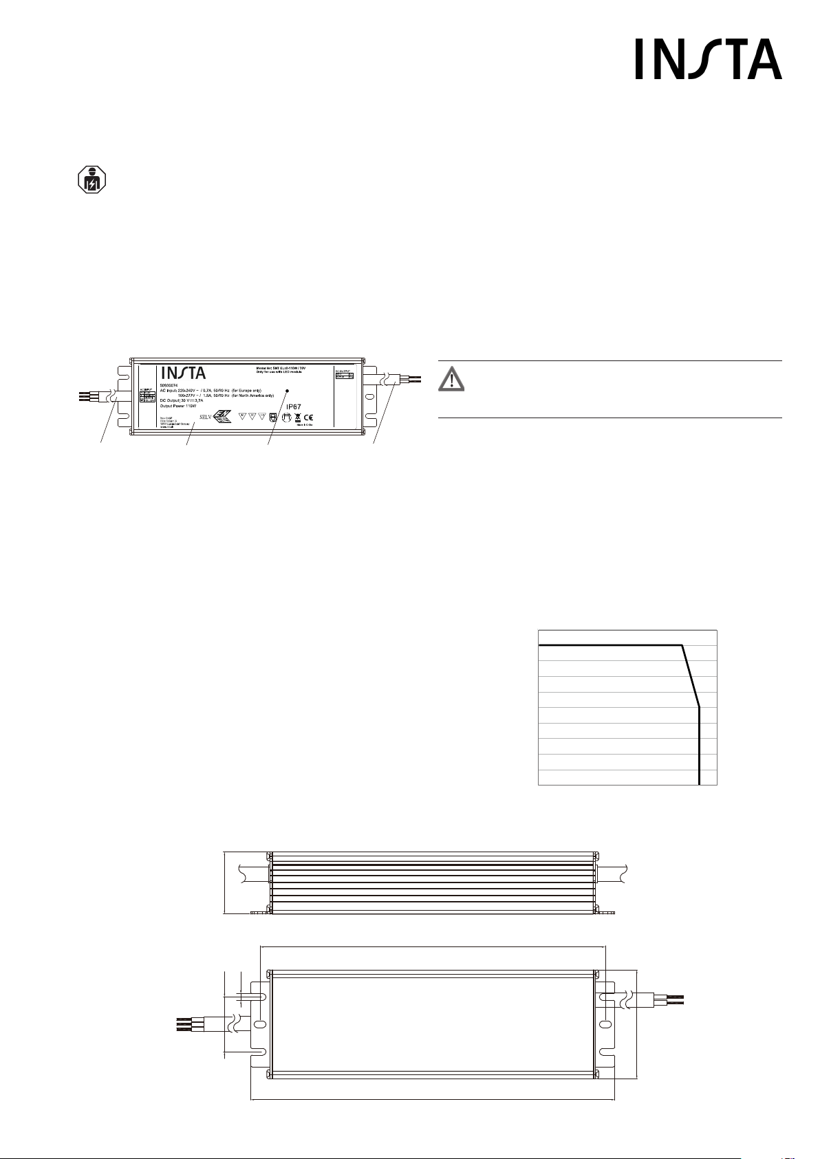
Geräteaufbau
(1) Netzleitung
(2) Gehäuse (IP 67)
(3) tc-Punkt
(4) Ausgangsleitung
Bild 1: Geräteaufbau
Funktion
Bestimmungsgemäßer Gebrauch
Das SNT ELI ist ein elektronisches Betriebsgerät zum Anschluss von
LED-Lampen, die mit Kleinspannung betrieben werden.
- Betrieb von LED-Lampen mit Kleinspannung (SELV) gemäß DIN
EN 61347-1 und DIN EN 61347-2-13
- Betrieb im Innen- und im Außenbereich
Geräteschutz
Der LED-Ausgang des Betriebsgerätes ist leerlaufsicher und verfügt
über folgende Schutzeinrichtungen:
- Elektronischer Kurzschlussschutz
- Elektronischer Überlastschutz
- Elektronischer Übertemperaturschutz
Im Falle eines Fehlers schaltet der Ausgang automatisch ab. Die
Wiedereinschaltung erfolgt selbständig nach Beseitigung des Fehlers.
Informationen für Elektrofachkräfte
Montage und elektrischer Anschluss
GEFAHR!
Lebensgefahr durch elektrischen Schlag.
Gerät freischalten. Spannungsführende Teile abdecken.
Gerät montieren
▪ Am Montageort vier Bohrungen entsprechend der in Bild 2
angegebenen Maße vornehmen.
▪ Versorgungseinheit mit vier Schrauben am Montageort anbringen.
▪ Für gute Belüftung um das Betriebsgerät herum sorgen und es
nicht abdecken. Wenn benachbarte Geräte Wärme erzeugen, ist
ein Abstand von 100 - 150 mm dazu einzuhalten.
Gerät anschließen
Der tc-Punkt (3) am Gehäuse darf im Dauerbetrieb unter Vollast eine
Temperatur von +80 °C nicht überschreiten. Andernfalls schaltet das
Gerät ab. Darum bei Betrieb in hoher Umgebungstemperatur eine
Lastreduzierung gemäß Bild 3 vornehmen.
03.05.2018
824 016 00
Bild 2: Gerätemaße
-40 -30 -20 -10 0 20 40 50 60 70
100
110
80
60
40
20
90
70
50
30
10
Load (%)
Ambient Temperature ta (°C)
17
(1) (2) (3) (4)
tc: 80 °C
221
208
40
4,2
34,2
69
Bild 3: Lastreduzierung

Insta GmbH
Postfach 1830
D-58468 Lüdenscheid
Telefon +49 (0) 2351 936-0
Anhang
Technische Daten
Nennspannung: AC 100 - 277 V ~
Netzfrequenz: 50/60 Hz
Eingangsstrom: 0,7 A bei 230 V AC
1,5 A bei 110 V AC
Anschlussleistung: 0 ... 110 W
Leistungsfaktor: ≥0,96 bei 230 V AC
Wirkungsgrad: 93 %
Sekundärspannung: DC 30 V =, SELV
Ausgangsstrom: 0 ... 3,7 A
Schutzklasse: I
Schutzart: IP 67
Umgebungstemperatur ta: -40 ... +60 °C
tc-Punkt-Temperatur: max +80 °C
Lager-/ Transporttemperatur: -40 ... +80 °C
Gehäuseabmessungen (L x B x H): 221 x 69 x 40 mm
Länge der konfektionierten Anschlussleitung: 300 ± 20 mm
Sekundärleitungslänge: max. 100 m
Gewicht: 1100 g
Gewährleistung
Wir leisten Gewähr im Rahmen der gesetzlichen Bestimmungen.
Bitte schicken Sie das Gerät portofrei mit einer
Fehlerbeschreibung an unsere zentrale Kundendienststelle:
Insta GmbH
Service Center
Hohe Steinert 10
D-58509 Lüdenscheid
Deutschland
03.05.2018
824 016 00
Leiter Netzseite Leitungsfarbe
Außenleiter L braun
Neutralleiter N blau
Schutzleiter PE grün/gelb
Leiter Sekundärseite Leitungsfarbe
V+ rot
V- schwarz
▪ Da die Aderenden der konfektionierten Anschlussleitungen verzinnt
sind, keine Schraubklemmen sondern Federsteckklemmen zum
Anschließen des elektronischen Betriebsgerätes verwenden.
▪ Alle Verbindungen möglichst kurz halten, um ein gutes EMV-
Verhalten sicherzustellen.
▪ Netzleitungen sollten vom elektronischen Betriebsgerät und
anderen Leitungen möglichst ferngehalten werden (idealer Abstand
mindestens 10 cm)
▪ Bei Installationen in feuchter Umgebung dafür sorgen, dass auch
die Leitungsverbindungen wasserdicht ausgeführt werden, damit
kein Wasser in das System eindringen kann.
Leitungsschutz
Maximale Anzahl von elektronischen Betriebsgeräten pro Stromkreis
beachten.
Leitungsschutzschalter Anzahl Betriebsgeräte
B 10 max. 3 Stück
B 16 max. 5 Stück
C 10 max. 5 Stück
C 16 max. 9 Stück
D 10 max. 10 Stück
D 16 max. 17 Stück
L
N
PE
SNT ELI 0 -110 W /30 V
L
NV+
V-
AC 100 - 277 V
/
▪ Anschluss gemäß Bild 4 vornehmen
Bild 4: Anschluss-Schaltbild
SNT ELI 0-110 W / 30 V – Operation manual
Art.-no.: 50930074
Safety instructions
Electrical equipment may only be installed and tted by electrically skilled persons.
Failure to observe the instructions may cause damage to the device and result in re and other hazards.
During installation and cable routing, comply with the standards and regulations which apply for SELV.
Do not connect the electronic operating device to a dimmer. The dimmer and operating device may get damaged.
Do not connect the electronic operating device to an electronic switch insert. The switch insert and operating device may get dama-
ged.
These instructions are an integral part of the product, and must remain with the end user.
Insta GmbH
P.O. Box 1830
D-58468 Lüdenscheid
Telephone +49 2351 936-0
Device components
(1) Mains cable
(2) Housing (IP 67)
(3) tc-point
(4) Output cable
Figure 1: Device components
Function
Intended use
SNT ELI is an electronic operating device for the connection of LED
lamps that are operated with extra low voltage.
- Operation of LED lamps with extra low voltage (SELV) according to
DIN EN 61347-1 and DIN EN 61347-2-13
- Operation indoors and outdoors
Device protection
The LED output of the operating device is no-load proof and has the
following protection devices:
- Electronic short circuit protection
- Electronic overload protection
- Electronic over-temperature protection
In the event of a fault, the output switches off automatically. The output
switches on again autonomously after eliminating the fault.
Information for electrically skilled persons
Fitting and electrical connection
DANGER!
Mortal danger of electric shock.
Disconnect the device. Cover up live parts.
Fitting the device
▪ At the installation location, drill four holes according to the
dimensions shown in Figure 2.
▪ Attach the supply unit to the installation location with four screws.
▪ Ensure good ventilation around the operating device and do
not cover it. If adjacent devices generate heat, keep a distance of
100 - 150 mm to them.
Connecting the device
The tc-point (3) on the housing must not exceed a temperature of
+80 °C in continuous operation under full load. Otherwise the device
switches off. Therefore, when operating in high ambient temperature,
reduce the load according to Figure 3.
2018-05-03
824 016 00
Figure 2: Device dimensions
-40 -30 -20 -10 0 20 40 50 60 70
100
110
80
60
40
20
90
70
50
30
10
Load (%)
Ambient Temperature ta (°C)
17
(1) (2) (3) (4)
tc: 80 °C
221
208
40
4,2
34,2
69
Figure 3: Load reduction

Insta GmbH
P.O. Box 1830
D-58468 Lüdenscheid
Telephone +49 2351 936-0
Appendix
Technical data
Rated voltage: AC 100 - 277 V ~
Mains frequency: 50/60 Hz
Input current: 0.7 A at 230 V AC
1.5 A at 110 V AC
Connected load: 0 ... 110 W
Power factor: ≥0.96 at 230 V AC
Efciency: 93 %
Secondary voltage: DC 30 V =, SELV
Output current: 0 ... 3.7 A
Protection class: I
Degree of protection: IP 67
Ambient temperature ta: -40 ... +60 °C
tc-point temperature: max. +80 °C
Storage/transport temperature: -40 ... +80 °C
Housing dimensions (L x W x H): 221 x 69 x 40 mm
Length of the pre-assembled connecting cable: 300 ± 20 mm
Secondary cable length: max. 100 m
Weight: 1100 g
Warranty
We provide a warranty as provided for by law.
Please send the unit postage-free with a description of the defect
to our central customer service ofce:
Insta GmbH
Service Center
Hohe Steinert 10
D-58509 Lüdenscheid
Germany
2018-05-03
824 016 00
Conductors on mains side Conductor colour
Live conductor L brown
Neutral conductor N blue
Protective conductor PE green-yellow
Conductors on secondary
side
Conductor colour
V+ red
V- Black
▪ Since the wire ends of the pre-assembled connecting cables are
tinned, do not use screw terminals but screwless terminals to
connect the electronic operating device.
▪ Keep all connections as short as possible to ensure good EMC
performance.
▪ Mains cables should be kept as far away as possible from the
electronic operating device and other lines (ideal distance
at least 10 cm)
▪ For installations in humid environments, ensure that also the line
connections are watertight so that no water can penetrate the
system.
Circuit breaker
Observe the maximum number of operating devices per circuit:
Circuit breaker Number of operating devices
B10 max. 3 pcs
B16 max. 5 pcs
C10 max. 5 pcs
C16 max. 9 pcs
D 10 max. 10 pcs
D 16 max. 17 pcs
L
N
PE
SNT ELI 0 -110 W /30 V
L
NV+
V-
AC 100 - 277 V
/
▪ Connection according to Figure 4
Figure 4: Wiring diagram
This manual suits for next models
2
Table of contents
Languages:
Other Insta Lighting Equipment manuals


