Maxcess H3257 User manual

H3257 LED Light Source
User Manual
EN
MI 1-921 1
FIFE GUIDING SOLUTIONS

CONTENTS
www.maxcessintl.com
Fife H3257
MI 1-921 1
INTRODUCTION 1-1
About these operating instructions ...................................................................... 1-1
CE marking .......................................................................................................... 1-1
Product overview .................................................................................................. 1-2
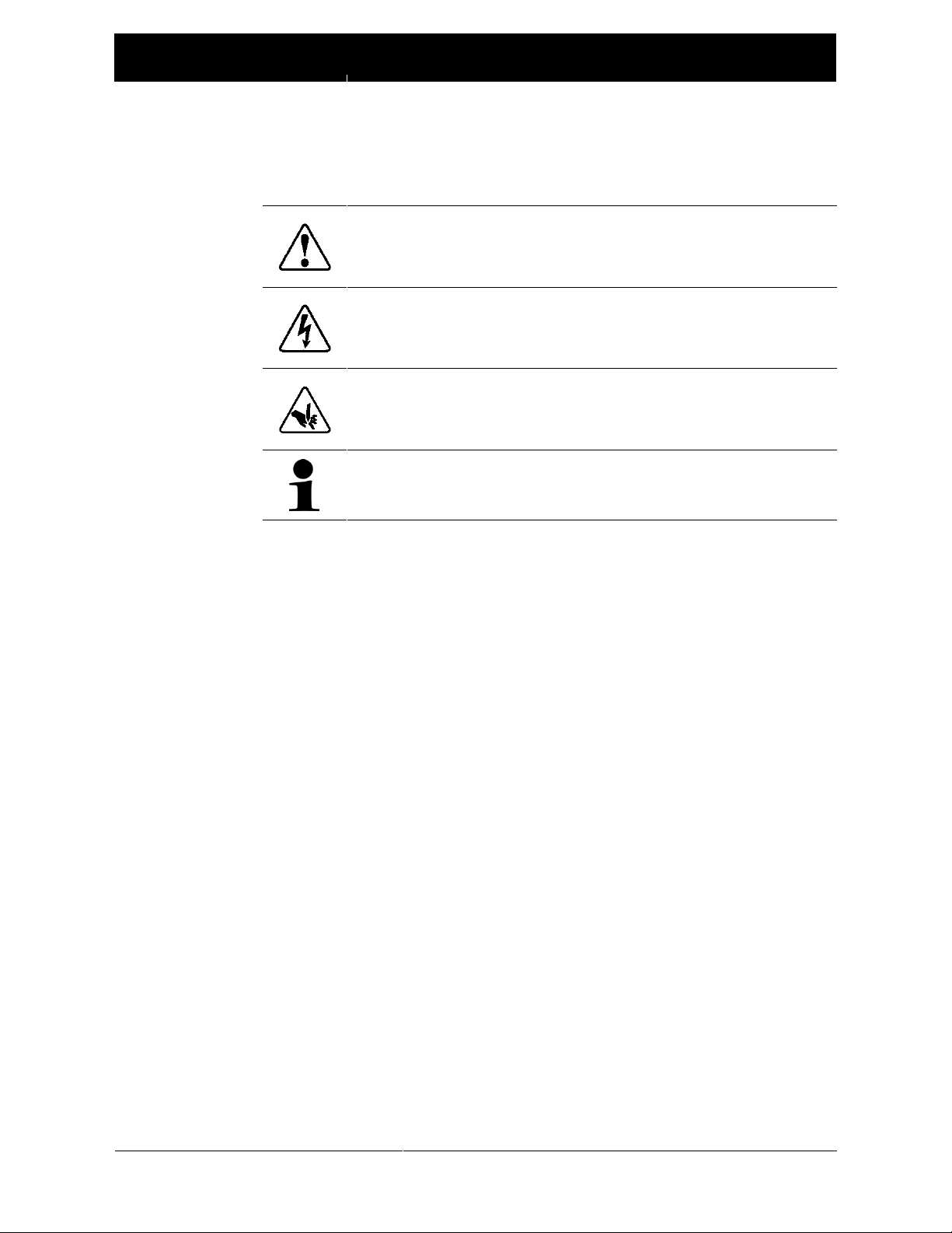
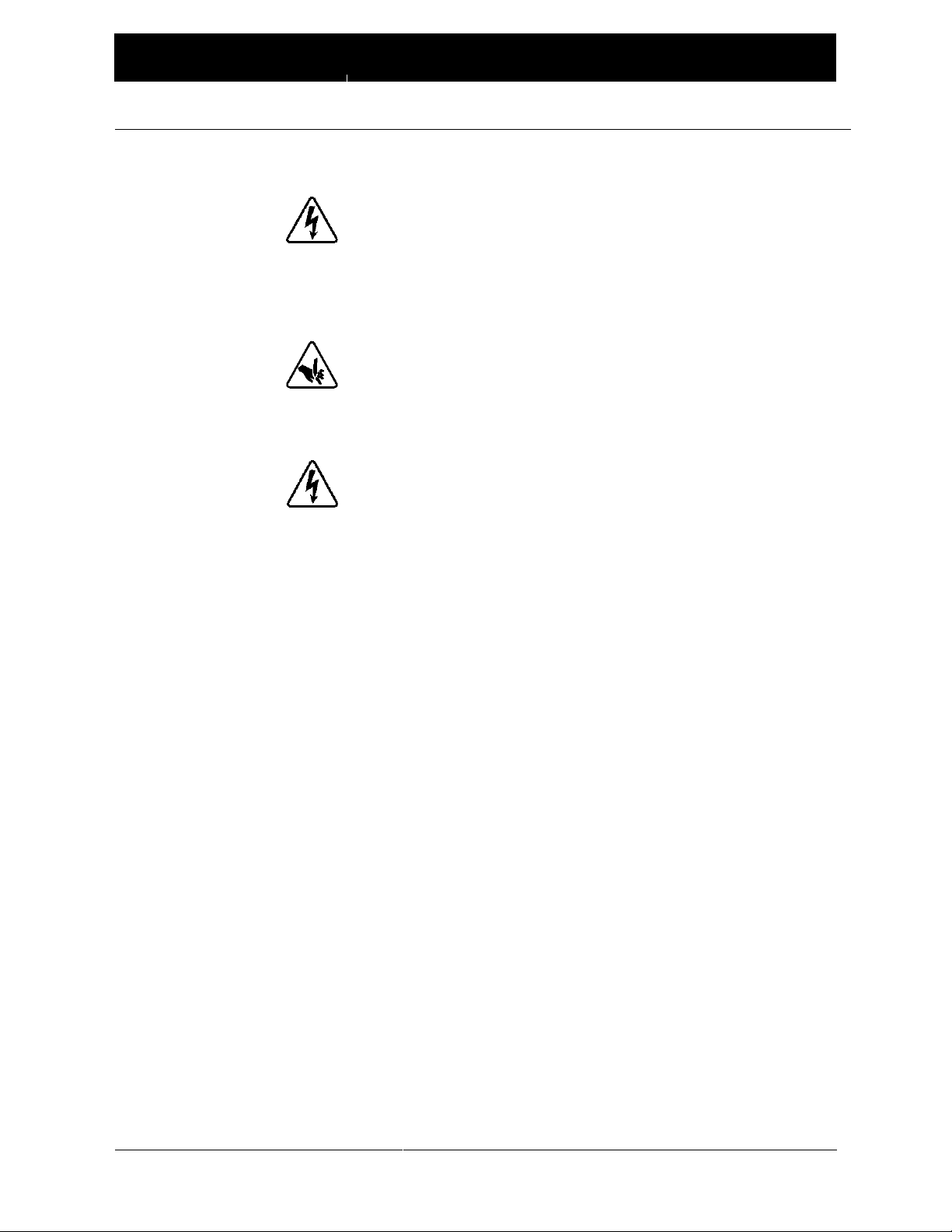
SAFETY INSTRUCTIONS 2-1
Hazards................................................................................................................ 2-3
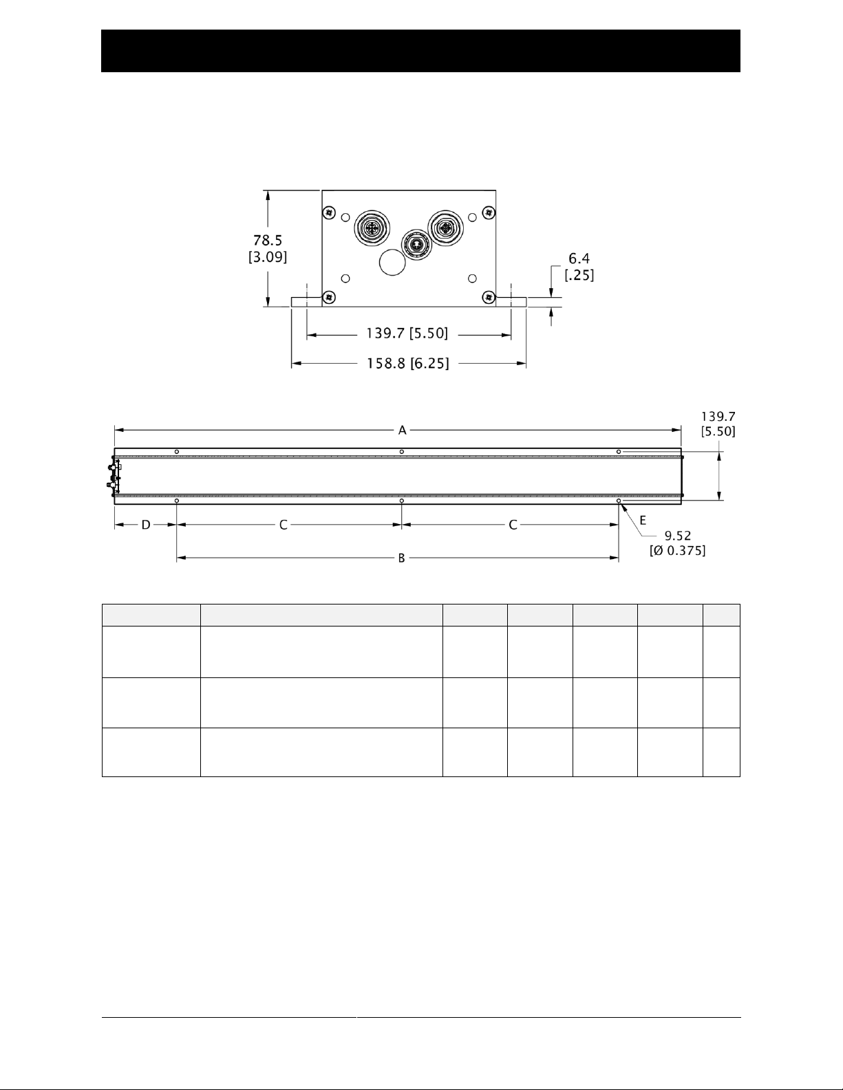
INSTALLATION 3-1
Product dimensions.............................................................................................. 3-1
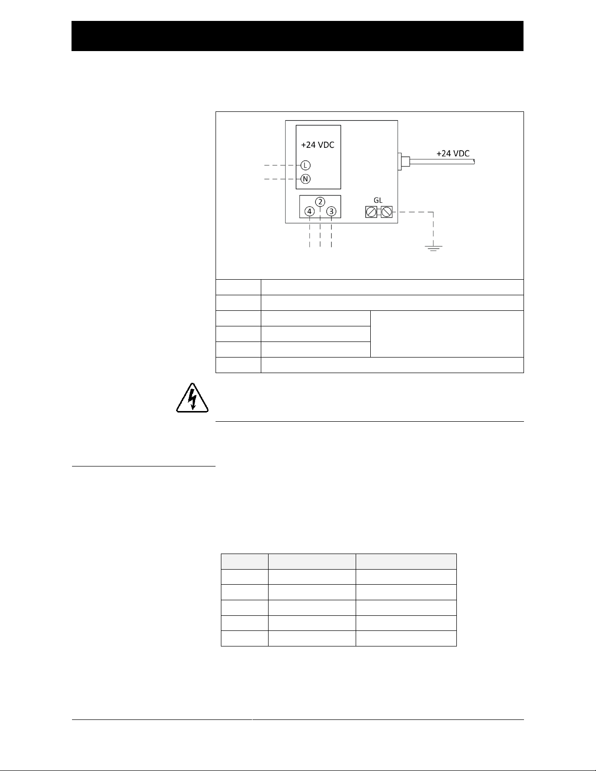
Power supply, +24V ............................................................................................. 3-2
Alternate power supply.................................................................................... 3-2
Components and cable connections..................................................................... 3-3
Single light source ........................................................................................... 3-3
Dual light source ............................................................................................. 3-3
Using the H3109 Discriminating Detector ............................................................ 3-4
OPERATION 4-1
Sensor gap ........................................................................................................... 4-1
Adjusting the light intensity ................................................................................. 4-2
Adjustment button .......................................................................................... 4-2
LED bar graph.................................................................................................. 4-2
DC light mode ...................................................................................................... 4-3
Dual H3257 synchronization ................................................................................ 4-3
TROUBLESHOOTING 5-1
MAINTENANCE 5-1
Lens ..................................................................................................................... 5-1
Spare parts........................................................................................................... 5-1
Replacing a fuse ................................................................................................... 5-1
SPECIFICATIONS 7-1
SERVICE 8-1

1-1
INTRODUCTION
www.maxcessintl.com
Fife H3257
MI 1-921 1
About these
operating
instructions
All of the information herein is the exclusive proprietary
property of Maxcess International, and is disclosed with the
understanding that it will be retained in confidence and will
neither be duplicated nor copied in whole or in part nor be
used for any purpose other than for which disclosed.
Copyright 2015, all rights reserved.
Periodically there will be updates to this manual. The latest
version is available on our website or by calling the number
on the back page of this publication.
This LED light source must not be installed or used in a
machine or system that does not comply with the machinery
directive 2006/42/EC.
This LED light source was designed and manufactured to be
installed as partly completed machinery into a machine or
partly completed machine.
The instructions must be read and used by all persons who
have the responsibility of installing and maintaining this LED
light source.
These instructions must be retained and incorporated in the
technical documentation for the machine or partly completed
machinery into which the LED light source is installed.
CE marking
This LED light source is marked with the CE sign according to
the EMC directive 2004/108/EC.

1-2
INTRODUCTION
www.maxcessintl.com
Fife H3257
MI 1-921 1
Conventions used in
this manual
All dimensions and specifications are shown in the format
mm [inches] unless specified otherwise.
Language
These are the original instructions, written in English.
Theory of operation
The H3275 LED Light Source is used as a backlight for an
optical sensor or camera in a web or strip guiding system. The
H3257 provides uniform LED light output through a diffusing
lens, which is captured by a sensor or camera to provide
information about the material position. The device can be
configured to emit 7.5 kHz light (pulsed) or DC light.
Factory-calibrated LED intensity levels can be easily selected
by actuating a pushbutton switch. An internal dry-contact
relay indicates the status of the light source.

2-1
SAFETY
www.maxcessintl.com
Fife H3257
MI 1-921 1
Instructions for use
Problem-free and reliable operation of the H3257 requires
that the system must be properly transported, stored,
installed, and placed in operation. Proper operation and
careful maintenance will ensure a long service life for your
system.
Only persons who are acquainted with the installation,
commissioning, operation, and maintenance of the system
and who possess the necessary qualifications for their
activities may work on the H3257. Note: The safety
information may not be comprehensive.
Please note the following:
The content of these operating instructions
Any safety instructions on the device
The machine manufacturer’s specifications
All national, state, and local requirements for installation,
accident prevention, and environmental protection
Safety symbols
The safety instructions and symbols described in this section
are used in these operating instructions. They are used to
avoid possible dangers for users and to prevent material
damage.
SIGNAL WORD
Source of danger and its results
Avoiding dangers
The signal word DANGER refers to the danger of death or
serious bodily injuries.
The signal word WARNING refers to the danger of moderate to
severe bodily injuries.
The signal word CAUTION refers to the danger of slight to
moderate bodily injuries or material damage.

2-2
SAFETY
www.maxcessintl.com
Fife H3257
MI 1-921 1
Symbols used
The following safety identification symbols are used in these
operating instructions.
WARNING/CAUTION –General danger or important note
Reference to general hazards that may result in bodily injuries
or damage to device or material.
DANGER –Danger due to voltage, electric shock
Reference to danger of injury caused by electric shock due to
voltage.
WARNING –Danger due to cutting
Reference to danger of injury caused by sharp edges
Reference to important information

2-3
SAFETY
www.maxcessintl.com
Fife H3257
MI 1-921 1
Basic safety information
Proper use
The H3257 is intended to be installed indoors in proximity to
a moving web or strip for the purpose of guiding the web
material.
Improper use
Operation outside the technical specifications
Operation in an Ex-area or intrinsically safe area
Outdoor operation
Any other use than the proper use shall be deemed
inappropriate.
Hazards
Installation and commissioning
WARNING –Death or injury can result from electrical shock.
Turn off and disconnect the power supply before connecting
or disconnecting any cable connectors. Damage to the
equipment caused by failure to do so may void the product
warranty.
Tighten all cable connectors sufficiently to provide the
required connection for the cable shielding.
Any component which is damaged must not be installed or
put into operation.
The H3257 must be securely mounted before being placed in
operation.
Only replacement parts obtained from Fife may be used.
No modifications may be made to the H3257.
Do not place cables under mechanical strain.
continued

2-4
SAFETY
www.maxcessintl.com
Fife H3257
MI 1-921 1
Hazards –continued
Operation
WARNING –Death or injury can result from static electric
shocks.
Moving webs of material can produce large static voltage
potentials. To protect against electric shocks, the system must
be properly grounded.
See Figure 1, page 3-2.
WARNING –Injury can result from cutting
Keep hands away from moving web material.
Maintenance and repair
WARNING –Death or injury can result from electrical shock.
Turn off and disconnect the power supply before connecting or
disconnecting any cable connectors. Damage to the equipment
caused by failure to do so may void the product warranty.
Decommissioning
The H3257 must be disposed of in accordance with all the
applicable national, state and local regulations.

3-1
INSTALLATION
www.maxcessintl.com
Fife H3257
MI 1-921 1
Product dimensions
Drawings not to scale
Part No.
Description
A
B
C
D
E*
290001165
Diffused LED Light Source 24.5"
619.8
[24.40]
457.2
[18.00]
X
81.3
[3.20]
4
290001198
Diffused LED Light Source 47"
1192.8
[46.96]
X
50.8
[20.00]
88.4
[3.48]
6
290001197
Diffused LED Light Source 92"
2336.8
[92.00]
X
990.6
[39.00]
177.8
[7.00]
6
Table 1. H3257 Part numbers and dimensions
* E indicates number of mounting holes

3-2
INSTALLATION
www.maxcessintl.com
Fife H3257
MI 1-921 1
Power supply
Fife part no. 29LH6610-PWR-80W (recommended)
Figure 1. +24 VDC Power supply.
L
Line
N
Neutral
2
NC (normally closed)
Power supply relay; driven by
the status signal
3
NO (normally open)
4
C (common)
GL
Ground lug
Ground to building ground bonding system per N.E.C. or local
codes.
Alternate power supply
If using a different power supply, connect the H3257 using a
5-pin M12 female-to-flying-lead cable.
See Table 2.
You will need to determine how devices in your system will
respond to the status signal.
Pin
Wire Color
Function
1
Brown
+10 to 30 VDC
2
White
No connection
3
Blue
Common
4
Black
No connection
5
Gray
Status
Table 2. Wiring information for 29LH6610-F5L-xS cable.

3-3
INSTALLATION
www.maxcessintl.com
Fife H3257
MI 1-921 1
Components and
cable connections
Single light source
Dual light source
Item
Description
Part number
1
H3257 LED Light Source
See Table 1.
2
Power/communication cable *
29LH6610-F5M-xS
3
Power supply, +24 VDC
See page 3-2.
29LH6610-PWR-80W
4
Termination plug (control system status relay)
29LH6610-SR-01
5
SYNC connector
Install DC mode plug** for DC light (non-pulsed) OR
290001255
Install synchronization cable for dual light source
29LH6610-M4M-xS
*
**
Use for connecting to power supply or another H3257.
One DC mode plug is required for each H3257 LED Light Source
Cable part numbers: x= length in meters
Figure 2. Components and cable connections.

3-4
INSTALLATION
www.maxcessintl.com
Fife H3257
MI 1-921 1
Using the H3109
Discriminating
Detector
There are special considerations when the H3257 is used as a
light source for the H3109 sensor.
1. Always set the H3257 to intensity 8 (default).
2. Always set the H3257 to operate in pulsed mode (default).
3. A 4.7kΩ (1/4 W) load resistor must be placed across the
H3109 output and COM.
On most controllers, the resistor can be placed across the
detector input (such as DET 1 or DET2) and the COM
terminals at the controller.
See Figure 3
.
Figure 3. Example of 4.7kΩ resistor installed on controller terminals.

4-1
OPERATION
www.maxcessintl.com
Fife H3257
MI 1-921 1
Operation
LED intensity settings
The H3257 functions as a stand-alone light source using
factory calibrated light intensity/profile settings.
Factory calibration sets the drive level of each LED to the
same value for each of eight profile settings.
See Table 3.
Intensity
setting
Relative LED
drive level
1
30%
2
40%
3
50%
4
60%
5
70%
6
80%
7
90%
8
100%
(default)
Table 3. H3257 intensity settings
Intensity setting versus
sensor gap
* Harsh or very dusty environments may require a higher
intensity setting.
(Keep the lens clean.
See
Maintenance; page 5-1.)
Gap (sensor to light source)
Intensity setting
2 feet [61 cm] or less
2*
Greater than 2 feet [61 cm]
8
When used with the H3109 Discriminating Detector, the
intensity must be set to level 8.
See page 3-4
.

4-2
OPERATION
www.maxcessintl.com
Fife H3257
MI 1-921 1
Adjusting the light
intensity
The H3257 must be powered on to change the intensity. The
device will retain the selected intensity level between power
cycles.
Adjustment button
Adjust the intensity level with a small pushbutton located
behind a hole plug on the front panel.
-Gently pry out the hole plug.
-Use a small, non-conductive tool to actuate the button.
-Each press of the button increases the intensity level by
10% of the maximum.
-Once the maximum intensity has been reached, the
intensity will revert to Setting 1 on the next button press.
LED bar graph
Next to the pushbutton is an 8-LED green bar graph.
Each lit LED in the bar graph represents one intensity level.
This H3257 is set at intensity level 4.
Dual light source only
This H3257 is operating as the slave.
In dual configuration, both light sources use the same
intensity, which is controlled and displayed on the master
light source.

4-3
OPERATION
www.maxcessintl.com
Fife H3257
MI 1-921 1
Enabling DC light mode
By default, the light emitted from the H3257 is pulsed at
7.5 kHz. When the H3257 is used as a light source for line scan
or array cameras, use DC light mode.
To configure the H3257 for DC light mode, the DC Mode Plug
must be installed on the 4-pin SYNC connector before turning
on the power.
See page 3-3
.
One DC mode plug is required for each H3257 LED Light
Source.
Enabling dual H3257
synchronization
The available lengths of the H3257 are sufficient to support
most applications. If necessary, two light sources may be used
to achieve the required length.
Dual light sources must be synchronized when used with a
single sensor. This occurs automatically when a synchroniza-
tion cable is installed between the 4-pin SYNC connector of
each H3257 prior to turning on the power.
See page 3-3
.
Table 4 summarizes the behavior of the H3257 based on the
configuration of the SYNC connector.
Quantity
of H3257s
SYNC Connection
(first H3257)
SYNC Connection
(second H3257)
Resulting Mode
1
No connection
n/a
Pulsed light
1
DC mode plug
n/a
DC light (single)
2
DC mode plug
DC mode plug
DC light (dual)
2
29LH6610-M4M-xS (x= length in meters)
Synchronized pulsed light
Table 4. Summary of H3257 light modes based on SYNC connector
Synchronization is not required if each H3257 is to operate in
DC light mode.
A power cycle must occur for synchronization or a light mode
change to occur.

5-1
TROUBLESHOOTING
www.maxcessintl.com
Fife H3257
MI 1-921 1
Problem
Status
contact
Possible cause
Solution
Cannot calibrate
detector
Closed
Light intensity may not
be sufficient.
Increase the intensity level.
DC light mode may be
enabled.
Remove the DC mode plug from
the SYNC connector, if present.
No light output
Open
n/a
Contact Maxcess for assistance.
Dim section of light
Open
n/a
Damaged or broken
lens
n/a
n/a
H3257 faults and
status contact
The H3257 provides a contact closure in series with the 5-
pin power connectors to indicate an internal fault to other
devices in the system.
The contact is closed during normal error-free operation.
The contact will be open under any of the following
conditions:
-Loss of power
-Internal microcontroller error
-Internal power supplies out of tolerance
-LED fault (entire 11" section of LEDs are open/short
circuit)

5-1
MAINTENANCE
www.maxcessintl.com
Fife H3257
MI 1-921 1
Maintenance
In some environments, dust and dirt will build up on the lens
of the H3257, reducing its effective light output.
Daily
Wipe the lens of the H3257 with a clean, damp, soft cloth.
Use ordinary soap and warm water.
Do not use abrasive materials or chemicals on the lens.
Damage may occur.
Do not soak or spray the detector with fluids.
Electrical damage may occur.
Spare parts
These parts are available from vendor.
Description
Part No.
4A slow-blow fuse
Littelfuse Inc.
0454004.MR
Circular hole plug
McMaster-Carr
9688K251
Replacing a fuse
WARNING –Death or injury can result from electrical shock.
Turn off and disconnect the power supply before performing
repairs.
1. Remove four screws (a).
2. Pull end plate connector assembly (b) away from the unit.
3. Pull the fuse (c) out of the holder and install new fuse.
4. Reinstall the end plate assembly.

7-1
SPECIFICATIONS
www.maxcessintl.com
Fife H3257
MI 1-921 1
Specifications
Compatible Sensors
H3218, H3218E, H3118, H3183, H3109, and DAC-005
Available Light Modes
Pulsed 7.5 kHz (single) This is the default.
DC Light (single or dual)
Synchronized (dual)
Voltage input
10 VDC to 30 VDC
Power requirements
5 W per 12 inches of product length
Protection class
IP65
Operating temperature
-20 to 50 °C (-4 to 122 °F)
Lens material
Polycarbonate
Status output
Contact closure indicates normal operation
Connectors
Two (2) for power
One (1) for synchronizing two light sources
Fuse
4A slow-blow (Littelfuse Inc / 0454004.MR)

8-1
SERVICE
www.maxcessintl.com
Fife H3257
MI 1-921 1
Return shipment
instructions
If it is necessary to return the product for service, package
the unit carefully to prevent damage during shipment. If
possible, use the original shipping containers.
Service requests and
replacement parts
When ordering replacement parts, please indicate, where
possible, part number, drawing number and model
description.
To request service or to get replacement parts, contact one
of the addresses listed below.
Maxcess
222 West Memorial Rd.
Oklahoma City, OK, 73114, USA
Phone: +1.405.755.1600
Fax: +1.405.755.8425
Web: www.maxcessintl.com
Fife-Tidland GmbH
Max-Planck-Strasse 8
65779 Kelkheim
Deutschland
Telefon: +49.6195.7002.0
Fax: +49.6195.7002.933
Web: www.maxcess.eu

EUROPE, MIDDLE EAST
AND AFRICA
Tel +49.6195.7002.0
Fax +49.6195.7002.933
www.maxcess.eu
© 2015 Maxcess
Table of contents
Popular Lighting Equipment manuals by other brands

Vision & Control
Vision & Control LDLF60x180-W5K7/24V Instructions for use

Ballard Designs
Ballard Designs LO484 manual

Larson Electronics
Larson Electronics LEDHWP-900-DNMS instruction manual

ETC
ETC Desire Fresnel user manual

Vision & Control
Vision & Control LDLF30x180-G525/UDC Instructions for use

Beamz
Beamz PS12W instruction manual