Adleepower AM Series User manual

ADLEEPOWER
INSTRUCTION MANUAL
THANK YOU VERY MUCH FOR YOUR PURCHASE
OF ADLEE PRODUCTS.
PLEASE READ THIS INSTRUCTION MANUAL
BEFORE INSTALLATION.
R
AM Brushless motors & BL drives

CONTENTS
1. PREFACE
2. RECEIVING
3. ENVIRONMENTAL REQUESTS
4. SPECIFICATION
5. DIMENSIONS
6. DIGITAL OPERATION PANEL .
7. TERMINALS AND WIRING
8. OPERATION AND CONNECTION
9. TROUBLE SHOOTING
Appendix
1
4
5
7
10
16
17
23
63
65

1. Preface
Thank you for purchasing ADLEEPOWER AM Brushless DC motor
and BL drives. Please read this manual thoroughly before installa-
tion and operation.
This manual should be stored by the user for maintenance refer-
ence and inspection.
Indicated a potentially hazardous situation which,
if not avoided, could result in death or serious
personnel injury.
Indicates a potentially hazardous situation which,
if not avoided, may result in minor or moderate
personnel injury and damage to equipment.
Danger
Caution
!
Danger
Only commence wiring after verifying that the power supply is turned
OFF.
Wiring should be performed only by qualified personnel.
Make sure to connect the ground terminal. Ground resistance 0.1
or less.
Do not measure any element signal during operation. Failure to observe
this caution can result in personal injury.
Perform maintenance or inspection only after verifying that the
CHARGE LED goes OFF 5 minute and after the main circuit power
source is turned OFF.
Never modify the product. Failure to observe this warning can result in
an electrical shock or personal injury and will invalidate the guarantee.
!
℃
Ω
1
Caution
Mount the driver on nonflammable material.(i.e. metal)
When mounting units in an enclosure, install a fan or other cooling
device to keep the intake air temperature below 45 .
Overheating may cause a fire or damage to the unit.
!
※
UVW
power input
2
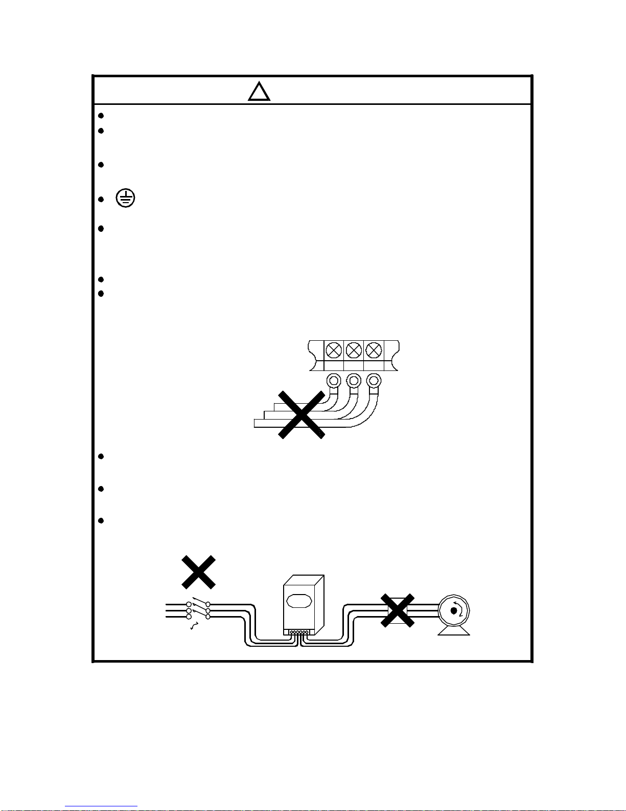
Caution
Please confirm power source voltage to driver input rated voltage.
Please make sure the wiring is correct when driver adds a braking
resister.
Do not put the advance phase capacitor between the driver and motor.
is grounding symbols. Be sure ground both the driver and motor.
Check the power connecter is locked on the terminal of driver.
( Do not looseness, otherwise, connecter will be oxidized and over
heat.)
Check that the input power source voltage is correct.
Be sure to connect the power source to L1,L2(input terminals) and the
motor to U.V.W.(output terminals). (Wrong connection will damage the
driver.)
Do not make any replacement for electronic parts when troubles are
occurred.
Do not perform a withstand voltage test of the driver. It may cause
semiconductor parts or power switches to be damage.
Do not install relay between power source and driver for operating
start and stop.
Phase advancing
capacitor
ON - OFF
Motor
power
source
Motor
BL
!
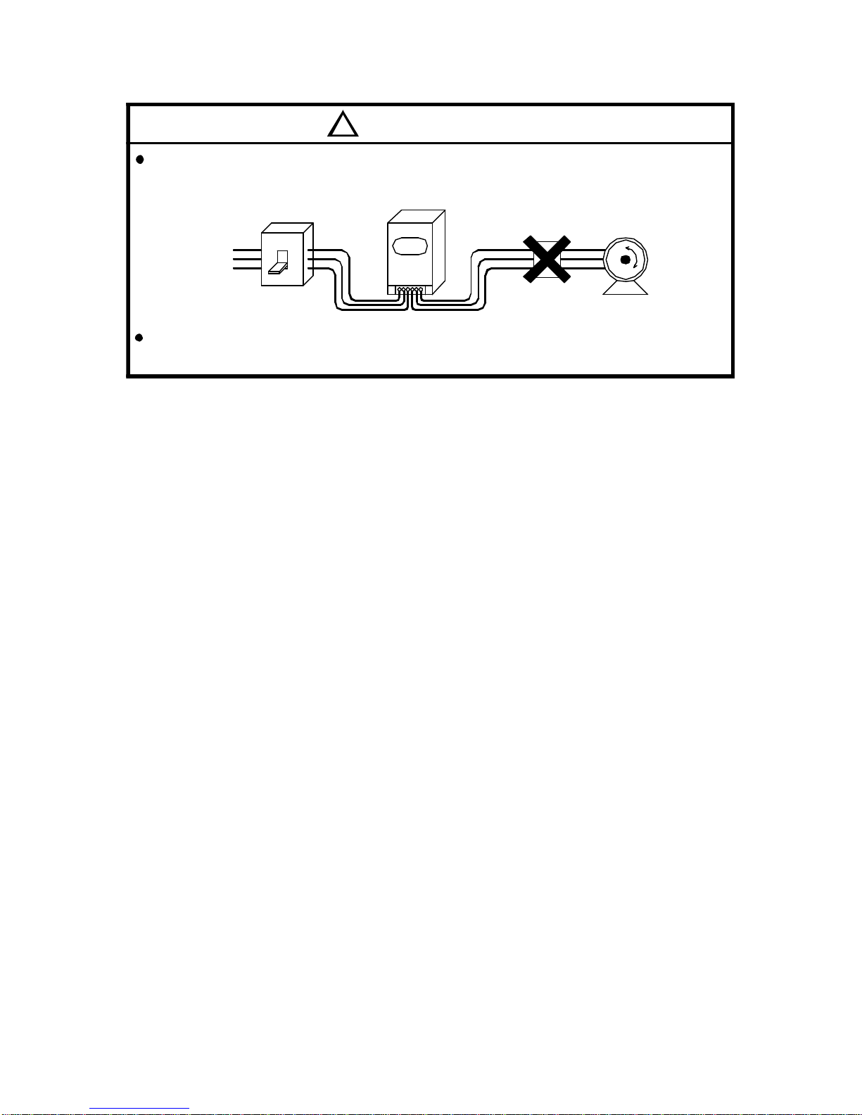
Caution
For operating motor "start" and "stop" should use keypad or terminal
to control these functions.
Do not install phase advancing capacitor between driver and motor
for operating motor.
3
ON - OFF
(NFB)
power
Motor
source
BL

4
Motor Drive
AM - XXX L (B) BL X - X XX X
: Rated power : example 370 represent 370W
: Rated speed : L : 2000RPM M : 3000RPM
H : 6000RPM HX : 9999RPM
: With B : with magnet brake
: Rated voltage : 2 : 220V 4 : 440V
: 1 : single phase input 3 : three phase input
: 01 : 0.1KW 02 : 0.2KW 04 : 0.4KW
07 : 0.75KW 15 : 1.5KW 22 : 2.2KW
Note : 60~370W motors and drives are with CSA approval.
j k l m n
j
k
l
m
o
n
o
2. Receiving
2-1 Acceptance Inspection and Precautions
During product manufacturing, packaging, and shipment
have been standardised. If any problem is discovered,
please contact your dealer or producer immediately.
Any damage with each product after shipping.
The instruction manual is contained in the package.
The product as same as an order (check the nameplate,
voltage and frequency).
All of terminals are locked and unusual substance.
The keyboard of remote control must be corrected.
Check the additional accessories.
2-2 Nameplate
Motor
Drive
k
MATCHSERVO MOTOR
ADLEE POWERTRONIC CO., LTD.
ADLEEPOWER
AMP.S
AMB.
R.P.M
MODEL
VOLTS
R
1.7A
3000
AM-370M
AC220V 370W
B
40
0~200Hz40 /104°C °F
DATE
IP
INS.
OUTPUT
Ambinent Temp
Rated current
Input voltage
Model No.
Rated rpm
Rated power
Implied protection
Insulation grade
Frequence grange
AC-INPUT
1 Rated 3.6A
200~230V 50/60Hz
ADLEE POWERTRONIC CO., LTD.
MATCHSERVO MTR DRIVES
ψ
AC-OUTPUT
370W Rated 1.70A
0~230V 3
BL2 - 104M
ψ
R
Output voltage & phase
Rated output power &
Input voltage & frequency
Model No.
Input phase & Rated current Rated current

3. Environmental requests
Operation
Storage
Transportation
Note :
a. Bad installation can reduce product service life.
b. Do not put motors and drives into worse environment. Such as
high temperature/humidity/vibration, corrosiveness gas, burst.
c. Keep enough cooling space for motors and drives.
Air temperature -20~60 (-4~140 )℃ ℉
Air pressure 86~106kPa
Humidity Less than 90%, no frosting
Air temperature -20~60 (-4~140 )℃ ℉
Air pressure 86~106kPa
Humidity Less than 90%, no frosting
Vibration Less than 20HZ : maximum 9.86m/s2
20~50HZ : maximum 5.88m/s2
5
Air temperature -10~45 (14~113 )℃ ℉
Air pressure 86~106kPa
Attitude Under 1000 meters
Vibration Less than 20HZ : maximum 9.86m/s2
20~50HZ : maximum 5.88m/s2

10cm 10cm
Motors
Drives
5cm 5cm
6

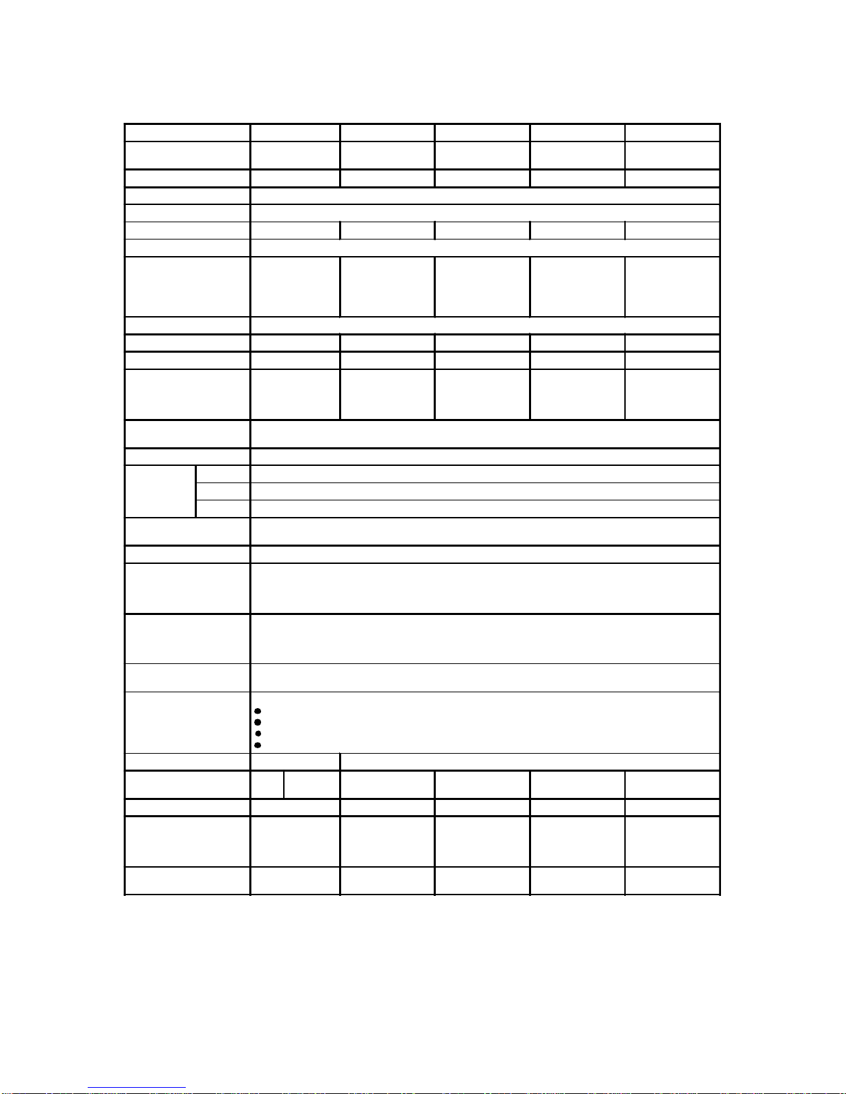
4. Specification
7
The varnished copper wire is F class insulation.
AM-60~370 motor has magnet brake option. The brake torque is 25Kg-cm
(21.6in-lb) and BL driver offers 24VDC to control it directly.
※ ∮
※ ∮
±
Ω
Ω
Rated Power W 60 90 120 180 250 370
Motor No. AM-60
L/M AM-90
L/M/H AM-120
L/M/H AM-180
L/M/H AM-250
L/M/H AM-370
L/M/H
Drive No. BL2-101 BL2-101 BL2-102 BL2-102 BL2-104 BL2-104
Input Voltage 220V 10% 1ψ
Input Frequency HZ 50 / 60
Rated input current 0.7 1.1 1.5 2.1 2.9 3.6
Motor Phase 3ψ
Rated Torque Kg-cm
(in-lb) 2.9/2.0
(2.5/1.7) 4.4/2.9/1.5
(3.8/2.5/1.3) 5.8/3.9/2.0
(5.0/3.4/1.7) 8.8/5.8/2.9
(7.6/5.0/2.5) 12.0/8.1/4.0
(10.4/7.0/3.5) 18.0/12.0/6.0
(15.6/10.4/5.2)
Rated Speed RPM L/M/H : 2000 / 3000 / 6000
Max. Efficiency % > 80 > 80 > 80 > 80 > 80 > 80
Max. Output W 180 220 280 330 450 600
Max. Torque Kg-cm
(in-lb) 12.0/6.0
(10.4/5.2) 15.0/9.0/5.5
(13.0/7.8/4.8)
18.0/12.0/8.0
(15.6/10.4/6.9)
27.0/18.0/10.5
(23.4/15.6/9.1)
36.0/24.0/13.0
(31.2/20.8/11.3)
54.0/36.0/20.0
(46.8/31.2/17.3)
Variable Speed Range
RPM L :150~2000 M :150~3000 H :300~6000
Acc. Dec. Time 0.1 ~ 600.0 Sec
Speed
regulation
Load ±1% Below (0~Rated Torque at rated speed)
Voltage ±1% Below (Source voltage±10% at rated speed No Load)
Temperature ±1%Below(-10~45 /14~113 atrated speed NoLoad)
℃ ℉
Motor Insulation/
Max. Working TEMP. BClass (130 /266 )/Max.100 /212
※ ℃ ℉ ℃ ℉
Type of control Rectangular wave PWM
Speed command
1. Built-in potentiometer
2.ExternalPotentiometer2k
≧
3. 0~5VDC, 0~10VDC, 4~20mA control
4.RS485
Operation
1. Pannel : CW、CCW、Key
2. Terminal : Type of input:Photocoupler, input impedance 2.2 k /
CW 、CCW、Common (4.5 ~ 5VDC)
3. Communication : RS485
Output signal Open collect output, External use condition DC48V、10mA below
SPEED OUT、Fault relay A/B
Protection
Any phenomenons as below will come to stop output alarm signal will be output and the
motor.
Over load:Motor over temperature protection.
Over heat:Power modular over heat shut down itself.
Lost phase:Motor signals are abnormal, due to motor cables was broken or
discounector.
Phase to phase short circuit.
Motor enclosure type IP40
Motor figure No. 1 1 2 3 4 5 4(M/H)
BL Driver figure No. 10 10 10 10 10 10
Motor Weight Kg
(lb) 2.1/2.1
(1.8/1.8) 2.4/2.4/2.4
(2.1/2.1/2.1) 2.6/2.5/2.5
(2.3/2.2/2.2) 2.9/2.7/2.7
(2.5/2.3/2.3) 4.0/3.8/3.7
(3.5/3.3/3.2) 4.5/4.0/4.0
(3.9/3.5/3.5)
BL Driver Weight Kg
(lb) 1.1
(1.0) 1.1
(1.0) 1.1
(1.0) 1.1
(1.0) 1.1
(1.0) 1.1
(1.0)

±
Ω
Ω
8
Rated Power W 750 1000 1500 2200
Motor No. AM-750M/H
CM-750L/M/HX AM-1000M/H AM-1500M/H
CM-1500L/M/HX AM-2200M/H
CM-2200L/M/HX
Drive No. BL2-107 BL2-115 BL2-115 BL2-122
Input Voltage 220V 10% 1ψ
Input Frequency HZ 50 / 60
Rated input current 7.55 10 13.4 18.6
Motor Phase 3ψ
Rated Torque Kg-cm
(in-lb)
AM:24.4/12.2
(21.1/10.6)
CM:36.6/24.4/9.1
(31.7/21.1/7.9)
AM:32.5/16.2
(28.2/14.0)
AM:48.8/24.4
(42.3/21.1)
CM:73.2/48.8/18.3
(63.4/42.3/15.9)
AM:73.2/36.6
(63.4/31.7)
CM:109.8/73.2/26.8
(95.1/63.4/23.2)
Rated Speed RPM L/M/H/HX:2000/3000/6000/9999
Max. Efficiency % > 85 > 85 > 85 > 85
Max. Output W 1600 2300 3000 4000
Max. Torque Kg-cm
(in-lb)
AM:48.8/24.4
(42.3/21.1)
CM:73.2/48.8/18.2
(63.4/42.3/15.8)
AM:65/32.4
(56.3/28.1)
AM:97.6/48.8
(84.6/42.3)
CM:146.4/97.6/36.6
(126.9/84.6/31.7)
AM:146.4/73.2
(126.9/63.4)
CM:210/146.4/53.6
(182/126.9/46.4)
Variable Speed Range
RPM L:150~2000 M:150~3000 H:300~6000 HX:300~9999
Acc. Dec. Time 0.1 ~ 600.0 Sec
Speed
regulation
Load ±1% Below (0~Rated Torque at rated speed)
Voltage ±1% Below (Source voltage±10% at rated speed No Load)
Temperature ±1%Below(-10~45 /14~113 atrated speed NoLoad)
℃ ℉
Motor Insulation/
Max. Working TEMP. BClass (130 /266 )/Max.100 /212
※ ℃ ℉ ℃ ℉
Type of control Rectangular wave PWM
Speed command
1. Built-in potentiometer
2.ExternalPotentiometer2k
≧
3. 0~5VDC, 0~10VDC, 4~20mA control
4. RS485
Operation
1. Pannel : CW、CCW、Key
2. Terminal : Type of input:Photocoupler, input impedance 2.2 k /
CW、CCW、Common (4.5 ~ 5VDC)
3. Communication : RS485
Output signal Open collect output, External use condition DC48V、10mA below
SPEED OUT、Fault relay A/B
Protection
Any phenomenons as below will come to stop output alarm signal will be output and
the motor.
Over load:Motor over temperature protection.
Over heat:Power modular over heat shut down itself.
Lost phase:Motor signals are abnormal, due to motor cables was broken or
discounector.
Phase to phase short circuit.
Motor enclosure type L:IP54 M/ H/HX:IP40
Motor figure No. AM:6
CM:A/A/D AM:7 AM:8
CM:B/B/E AM:9
CM:C/C/F
BL Driver figure No 10 11 11 11
Motor Weight Kg
(lb)
AM:8.0/7.8
(6.9/6.8)
CM:11.0/11.0/14.2
(9.5/9.5/12.3)
AM:9.4/8.7
(8.1/7.5)
AM:11.0/9.7
(9.5/8.4)
CM:14.0/14.0/15.3
(12.0/12.0/13.2)
AM:13.2/16.5
(11.4/14.3)
CM:15.6/15.6/16.5
(13.5/13.5/14.3)
BL Driver Weight Kg
(lb) 1.1
(1.0) 1.3
(1.1) 1.3
(1.1) 13
(1.1)
9
Ω
Ω
±
Rated Power W 370 750 1000 1500 2200
Motor No. AM-370L/M/H AM-750M/H
CM-750L/M/HX AM-1000M/H AM-1500M/H
CM-1500L/M/HX AM-2200M/H
CM-2200L/M/HX
Drive No. BL4-304 BL4-307 BL4-315 BL4-315 BL4-322
Input Voltage 380/440V 10% 3ψ
Input Frequency HZ 50 / 60
Rated input current 1.4 2.2 3.0 3.5 5.0
Motor Phase 3ψ
Rated Torque Kg-cm
(in-lb)
AM:18.0/12.0/6.0
(15.6/10.4/5.2)
AM:24.4/12.2
(21.1/10.6)
CM:36.6/24.4/9.1
(31.7/21.1/7.9)
AM:32.5/16.2
(28.2/14.0)
AM:48.8/24.4
(42.3/21.1)
CM:73.2/48.8/18.3
(63.4/42.3/15.9)
AM:73.2/36.5
(63.4/31.6)
CM:109.8/73.2/26.8
(95.2/63.4/23.2)
Rated Speed RPM L/M/H/HX:2000/3000/6000/9999
Max. Efficiency % > 85 > 85 > 85 > 85 > 85
Max. Output W 600 1600 2300 3000 4000
Max. Torque Kg-cm
(in-lb) AM:54/36/20
(46.8/31.2/17.3)
AM:48.8/24.4
(42.3/21.1)
CM:73.2/48.8/18.2
(63.4/42.3/15.8)
AM:65/32.4
(56.3/28.1)
AM:97.6/48.8
(84.6/42.3)
CM:146.4/97.6/36.6
(126.9/84.6/31.7)
AM:146.4/73.2
(126.9/63.4)
CM:210/146.4/53.6
(182/126.9/46.4)
Variable Speed Range
RPM L:150~2000 M:150~3000 H:300~6000 HX:300~9999
Acc. Dec. Time 0.1 ~ 600.0 Sec
Speed
regulation
Load ±1% Below (0~Rated Torque at rated speed)
Voltage ±1% Below (Source voltage±10% at rated speed No Load)
Temperature ±1%Below(-10~45 /14~113 atrated speed NoLoad)
℃ ℉
Motor Insulation/
Max. Working TEMP. BClass (130 /266 )/Max.100 /212
※ ℃ ℉ ℃ ℉
Type of control Rectangular wave PWM
Speed command
1. Built-in potentiometer
2.ExternalPotentiometer2k
≧
3. 0~5VDC, 0~10VDC, 4~20mA control
4. RS485
Operation
1. Pannel : CW
、
CCW
、
Key
2. Terminal : Type of input
:
Photocoupler, input impedance 2.2 k /
CW
、
CCW
、
Common (4.5 ~ 5VDC)
3. Communication : RS485
Output signal Open collect output, External use condition DC48V
、
10mA below
SPEED OUT
、
Fault relay A/B
Protection
Any phenomenons as below will come to stop output alarm signal will be output and the motor.
Over load
:
Motor over temperature protection.
Over heat
:
Power modular over heat shut down itself.
Lost phase
:
Motor signals are abnormal, due to motor cables was broken or discounector.
Phase to phase short circuit.
Motor enclosure type L/M/H:IP40 L:IP54 M/H/HX:IP40
Motor figure No. 5 4(M/H) AM:6
CM:A/A/D AM:7 AM:8
CM:B/B/E AM:9
CM:C/C/F
BL Driver figure No 10 11 11 11 11
Motor Weight Kg
(lb) AM:4.5/4.5/4.0
(3.9/3.9/3.5)
AM:8.0/7.8
(6.9/6.8)
M:11/11/14.2
(9.5/9.5/12.3)
AM:9.4/8.7
(8.1/7.5)
AM:11/9.7
(9.5/8.4)
CM:14/14/15.3
(12.1/12.1/13.3)
AM:13.2/16.5
(11.4/14.3)
CM:15.6/15.6/16.5
(13.5/13.5/14.3)
BL Driver Weight Kg
(lb) 1.1
(1.0) 1.3
(1.1) 1.3
(1.1) 1.3
(1.1) 1.3
(1.1)

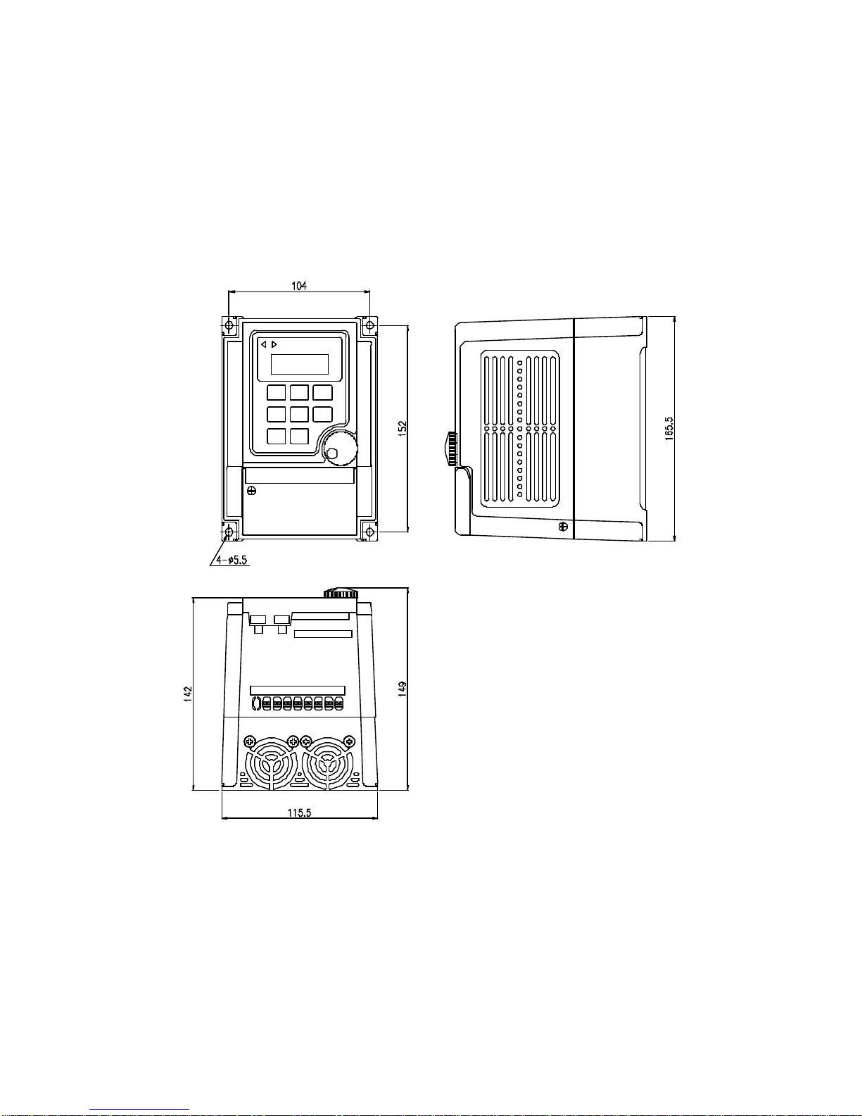
5. Dimensions
5-1 Drive dimensions
BL2-101~107,BL4-304 Unit : mm
10
BL2-115~BL2-122,BL4-307~BL4-322 Unit : mm
11
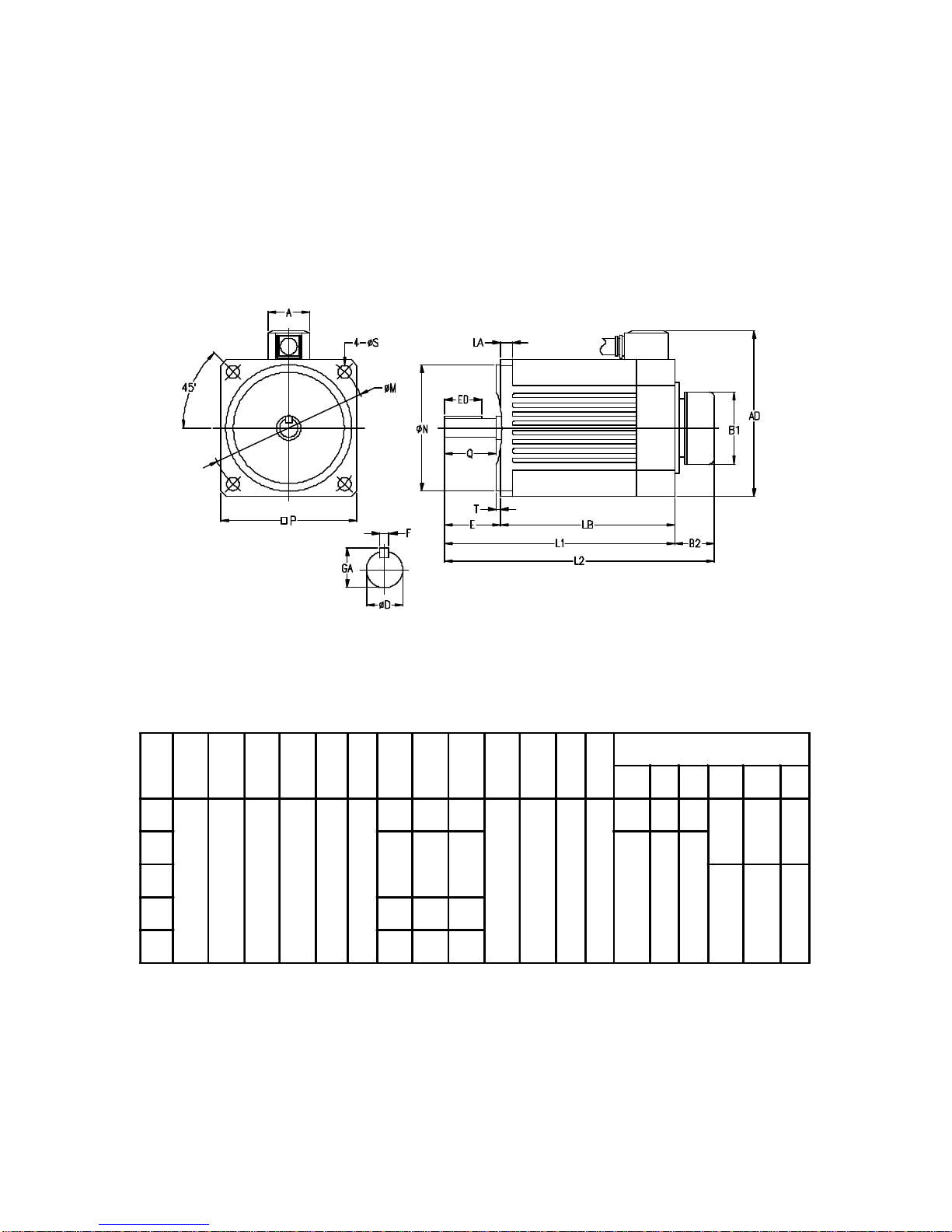
5-2 Motor dimensions
AM-60~370 Unit : mm
12
Wires colors : U(red), V(white), W(black).
No. P M∮S∮N∮TLA LB L1 L2 AD AB1 B2 OUTPUT SHAFT END
ED QED∮GA F
1
90 104 8.5 83 2.5 8
100 128 161
109 27 61 33
20 25 28 12 13.5 4
2115 147 180
25 29 32
3
14 16 54 170 202 235
5 185 217 250
□
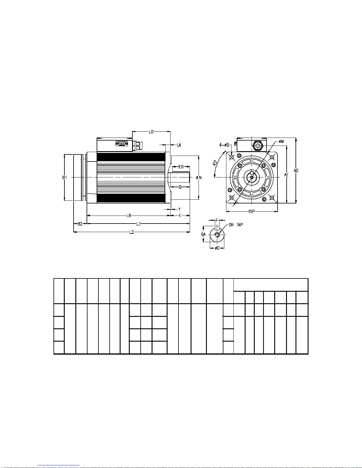
AM-750~AM-2200 Unit : mm
13
No. P M∮S∮N∮TLA LB L1 L2 B1 B2 AD AE LD OUTPUT SHAFT END
ED QED∮GA FDH
6
130 145 9 110 3.5 12
178 218 252.3
117 34.3 165.5 146
63 35 40 40 19 21.5 6M6
7 195 245 279.3 80
45 50 50 24 27 8 M88 212 262 296.3 97
9 232 282 316.3 117
□

CM-750~CM-2200 Unit : mm
14
No. P M∮S∮N∮TLA LB LAC AD AE LD OUTPUT SHAFT END
ED QED∮GA FDH
A
175 165 12 130 3.5 13
205 245
142
186 166
67 35 40 40 19 21.5 6M6
B239 289 101 45 50 50 24 27 8 M8
C259 309 121
D287 327
144 67 35 40 40 19 21.5 6M6
E337 45 50 50 24 27 8 M8
F296 346 76
□

5-2 F306 dimensions
Unit : mm
15
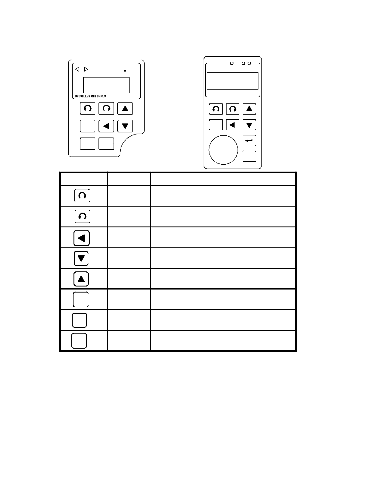
6. Digital operation panel
REV FWD
FUNC
STOPPROG
BL2 IPM
FUNC
STOP
F306 FWD
CHARGE
REV
REMOTE CONTROL
PROG
FUNC
STOP
16
Keypad Function Description
Forward
run Commands forward run
Reverse
run Commands reverse run
Cursor
movement Select the digit
Down Decrease the parameter value 9~0
Up Increase the parameter value 0~9
Memory
storage Saves the setting parameter value
Function Press once to select function code and
press again to change its content
Stop Stop operation / Escape to standby mode
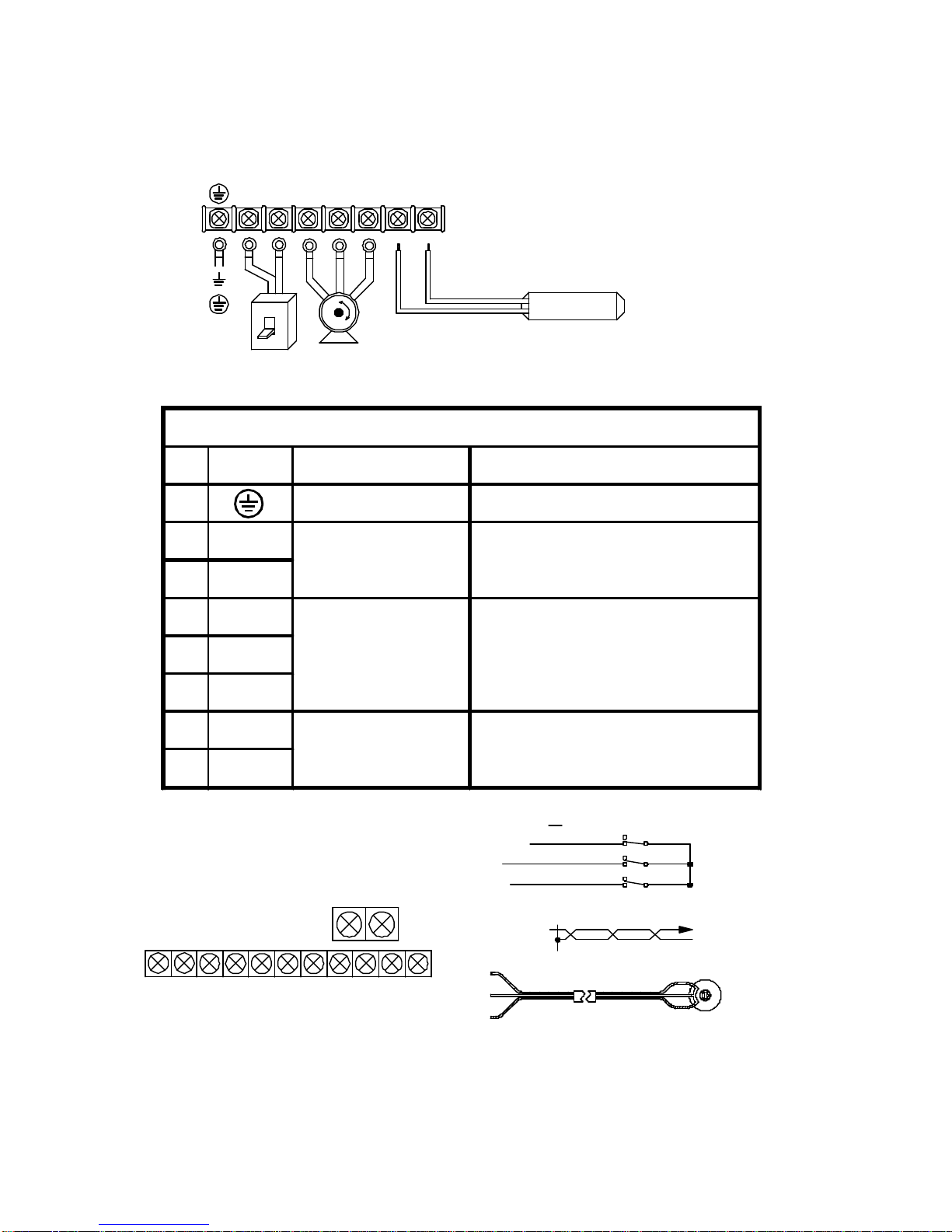
7. Terminals and wiring
7-1 Main power circuit terminals
7-2 Control terminals
17
L1 L2 UVWPRP
Motor
Power
Ground External braking resistor
Refer to the appendix
Source
OUT
SPEED
HMA/BLCCW
CF CCW EXG24V
MB+
MB-
+24 EXTERNAL POWER INPUT
SPEED SELECTION
CW. Input
CCW. Input
SPEED OUTPUT
OFF
ON
ON
OFF
OFF
ON
11 INPUT COM
6 CF
7 CW
8 CCW
4 A/B
9 SPEED OUT
5 C
1 H
2 M
3 L
EXG
3
2
1 3
21
SPEED KNOB(OPTIONS)
EXG
EXG
Main circuit terminal
No. Symbol Terminal name Description
1Ground Ground (Earth) Terminal
2 L1 Connect power
supply (L1, L2) Single Phase
3 L2
4U
Driver output
Terminal connecting to motor
U(red), V(white), W(black)
wrong UVW connection can
damage motor driver
5V
6W
7PDynamic brake
resistor See appendix for braking
resistor selection
8PR
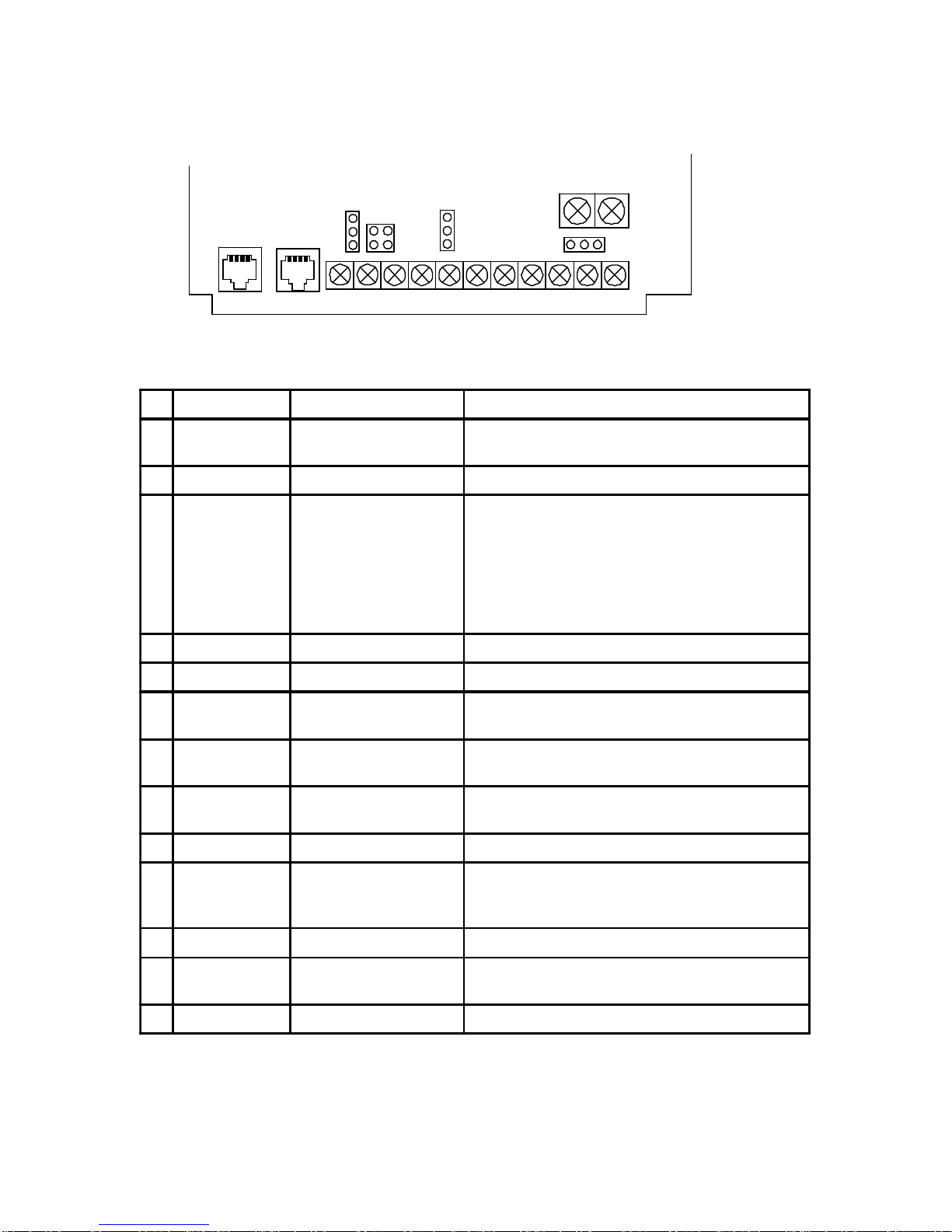
7-3 Control terminals descriptions
All terminal can connect to switch, relay, TTL or Transistor. Refer
to 8-3 for detail.
18
SPEED
A/BLCCW CCW OUT
HMCF EXG 24V
J4
J5
S161
J6
MB+
MB-
HallRS485 sensor
No Symbol Terminal name Description
1A/B Alarm output Fault alarm contact. Set J4 jumper for A
(normal open) or B (normal close).
2CAlarm output common Fault alarm contact C.
3CF Analog and digital
speed input selection
CF/EXG open : Analog speed input is from
panel VR or F306 VR. Digital speed input is
CD28 or CD34 setting. Set J5 jumper for panel
VR or F306 VR selection.
CF/EXG short : Analog speed input is from
external VR by H M L terminals. Digital speed
input is CD29 or CD35 setting.
4CW Forward operation Forward operation / stop terminal.
5CCW Reverse operation Reverse operation / stop terminal.
6SPEED OUT Speed signal output L, M model : 12 pulses/turn
H, HX model : 6 pulses/turn
7EXG Common terminal Common for terminal 3~6 or for external
24VDC(20mA)
824V External 24VDC input +24VDC external power input. Set S161
jumper to select internal or external power.
9H+10 VDC External VR reference voltage.
10 MAnalog command input External analog speed command input. Set J6
jumper for voltage 0~5VDC, 0~10VDC or
4~20mA.
11 LH and M common
MB- Motor brake - 24VDC, 15W, connect to magnet brake for
60~370W motor only
MB+ Motor brake +
This manual suits for next models
45
Table of contents
Other Adleepower DC Drive manuals

Popular DC Drive manuals by other brands


Aumuller
Aumuller KS2 Twin Assembly and commissioning instructions

Rowan Elettronica
Rowan Elettronica 390S.B instruction manual

SEW-Eurodrive
SEW-Eurodrive MGF-DSM Series Addendum to the operating instructions

Rockwell Automation
Rockwell Automation Allen-Bradley 1336 PLUS II instructions

Lenze
Lenze L-force 8400 Series Mounting instructions

Siemens
Siemens SINAMICS G120 installation manual