Adleepower AM-60L User manual
ADLEEPOWER
INSTRUCTION MANUAL
THANK YOU VERY MUCH FOR YOUR PURCHASE
OF ADLEE PRODUCTS.
PLEASE READ THIS INSTRUCTION MANUAL
BEFORE INSTALLATION.
R
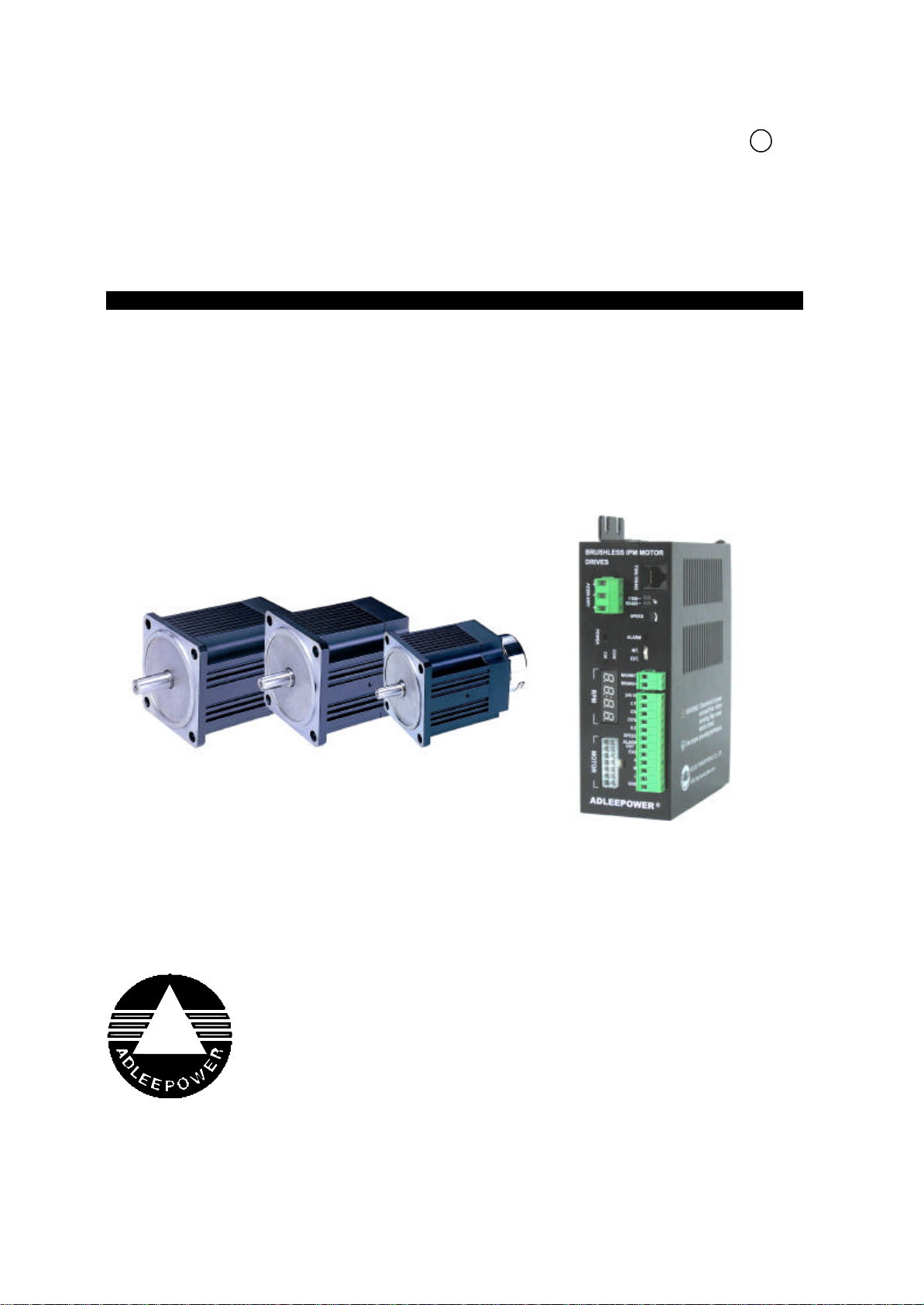
BRUSHLESS IPM
MOTOR & DRIVES

CONTENTS
1. PREFACE
2. NAMEPLATE
3. SPECIFICATION
4. DIMENSIONS
5. ENVIRONMENTAL REQUESTS
6. FUNCTION DESCRIPTION .
7. OPERATION AND CONNECTION
8. Motor T-N curve
9. APPLICATION
10. TROUBLE SHOOTING
11. REPAIRING AND MAINTENANCE
Appendix
1
5
6
8
11
13
21
63
64
65
67
70
1. Preface
This D305 drive and brushless servomotor made by ADLEE
Powertronic., Ltd.
Read this instruction manual throughly before operation.
This manual will be helpful in the installation, parameter setting
and troubleshooting of the BLDC motors and drives. To guarantee
safe operation of the equipment, read the following safety guide-
lines before connecting power to the drives. Keep this operating
manual handy and distribute to all users for reference.
Safety Precaution - Read These First
Indicates a potentially hazardous situation which, if against, may
result in personal injury, fire or damage to equipment.
DANGER
Do not install or operate motor or drive that are
damaged or has missing parts.
CAUTIION
Before installation, check specifications are
matched the equipment. Ex. voltage, power,
torque, RPM...
!
Receiving
!
!
Dangerous Electrical Shock
Danger and Caution
1

℃
2
Installation
!
!
!
℉
CAUTION
Impacts and shocks applied to the shaft end will
damage the rotary sensor and ball bearings. Pay
more attention when drive elements such as
pulleys, clutch disks, toothed wheels etc.
DANGER
Be sure to install the unit on flame-resistant material
such as a steel plate. Otherwise, there is the
danger of fire.
DANGER
Install units into a flowing air environment. See
inside manual requests. When mounting units in an
enclosure, install a cooling device to keep the
intake air temperature below 45 (115 ).
DANGEROUS ELECTRICAL VOLTAGE
Due to the permanent magnet excitatiion, the power
connector carries a hazardous high voltage if the
rotor is rotating and the motor is not electrically
connected. The unit must be completely
de-energized and halted before commencing any
connection or installation work.
CAUTION
Wiring should be performed only by qualified
personnal.
DANGER
For equipment protection, install a ground leakage
type breaker with a fast response circuit capable of
handling large currents.
Wiring
!
!
CAUTION
Hazardous terminals for any interconnection (motor,
contact breaker, filter, etc.) must be inaccessible in
the final installation.
DANGEROUS ELECTRICAL SHOCK
Be sure that the input voltage is matched the drive
specifications.
DANGEROUS ELECTRICAL SHOCK
Be sure not to connect an AC power supply to the
output terminals.
DANGEROUS ELECTRICAL SHOCK
Be sure to connect the grounding terminal to earth
ground. Ground resistance is less than 100 .
DANGEROUS ELECTRICAL SHOCK
Never remove connectors by pulling on its wire
leads. Otherwise, there is a danger of fire or injury
due to wire breakage.
CAUTION
Do not stop operation by switching of
electromagnetic contactors on the primary.
CAUTION
Tighten terminal screws.
CAUTION
When using D305 drives should match to
ADLEEPOWER®AM series motors. If using other
brand motors can cause the driver or motor dam-
age.
!
3
Ω
!
!
!
CAUTION
Danger of getting burnt! The surfaces of motors can
reach temperatures of up to approx. 100 (212 ).
A touch guard is to be provided where necessary.
DANGER
Danger of injury from shaft keys being slung out.
Motor may only be operated as installed.
CAUTION
Since it is easy to change operation direction or
speed from low to high speed. Verify the safe
working range of the equipment.
DANGEROUS ELECTRICAL SHOCK
To wait at least five minutes after turning off the
input power supply before performing maintenance
or an inspection. Otherwise, there is the danger of
electric shock.
DANGEROUS ELECTRICAL SHOCK
Never test the withstand voltage(HIPOT) on the
drive. It may cause components to be damaged.
DANGEROUS ELECTRICAL SHOCK
Never modify the unit. Otherwise, ther is danger of
electric shock and/ or injury.
℃
℉
Operation
Maintenance and Inspection
4
!
!
!

2. Nameplate
Motor
Drive
D305 ( B ) - 1
: With B : with magnet brake
: 1 : 110Vac : input source voltage 110Vac, output 220Vac
2 : 220Vac : input source voltage 220Vac, output 220Vac
j k
j
k
AM - XXX L (B)
: Rated power : example 370 represent 370W
: Rated speed : L : 2000RPM M : 3000RPM H : 6000RPM
: With B : with magnet brake
j k l
j
k
l
5
200~230V 50/60Hz
SINGLE PHASE 3.8A
AC-INPUT
Model:D305
ADLEE POWERTRONIC CO., LTD.
BLDC DRIVE
ADLEEPOWER
AC-OUTPUT
0~230V 3PHASE
180W 2.2A
DATE:
RManufacturing date
Rated Output power &
Output Voltage & PhaseInput Voltage & Frequency
Input phase & Max. Input
Model No.
Current Max. Current
ADLEEPOWER
Brushless DC Motor
ADLEE POWERTRONIC CO., LTD.
Model
Volts
AMP.S
AMB
Max. rpm
IP
Output
INS.
DRIVE
DATE
AM-180L
AC220V
0.55
45°C/113°F
2000
180W
40
B
R
Manufacturing date
Drive model
Implied protection
Rated powerModel No.
Input voltage
Rated current
Ambinent Temp
Max. rpm
Insulation grade
D305

3. Specification
6
Model No. AM-60
L/M AM-90
L/M/H AM-120
L/M/H AM-180
L/M/H AM-250
L/M/H AM-370
L/M/H
Input Voltage 100~130VAC / 1ψ OR 200~230VAC / 1ψ (TN system)
Input Frequency HZ 50 / 60
Input Rated Current A 0.7 1.1 1.5 2.1 2.9 3.6
Max. Input Current A
(For 220V input) 2.8 3.4 4.2 56.5 8.5
Max. Input Current A
(For 110V input) 5.6 6.2 7.3 10 11.6 15
Output Rated Current A 0.4 0.6 0.8 1.1 1.6 2.2
Max. Output Current A 1.8 22.4 3.2 4.1 4.9
Overload Current
Protection (A) 2.0/2.4 2.4/2.4/2 2.6/3.2/3.0 3.6/4.4/3.5 5.0/5.6/5.0 6.4/6.6/6.4
Motor Rated Current A 0.32/0.34 0.45/0.45/0.43 0.61/0.64/0.52 0.94/0.94/0.78 1.45/1.15/1 1.92/1.7/1.4
Motor Phase 3ψ
Rated Output W 60 90 120 180 250 370
Rated Torque Kg-cm
(in-lb) 2.9/2.0
(2.5/1.7) 4.4/2.9/1.5
(3.8/2.5/1.3) 5.8/3.9/2.0
(5.0/3.4/1.7) 8.8/5.8/2.9
(7.6/5.0/2.5) 12.0/8.1/4.0
(10.4/7.0/3.5) 18.0/12.0/6.0
(15.6/10.4/5.2)
Rated Speed RPM L:2000 / M:3000 / H:6000
Max. Efficiency % > 80 > 80 > 80 > 80 > 80 > 80
Max. Output W 180 220 280 330 450 600
Max. Torque Kg-cm
(in-lb) 12/6
(10.4/5.2) 15/9/5.5
(13.0/7.8/4.8) 18/12/8
(15.6/10.4/6.9) 27/18/10.5
(23.4/15.6/9.1) 36/24/13
(31.2/20.8/11.3) 54/36/20
(46.8/31.2/17.3)
Variable Speed Range RPM L:150~2000 / M:150~3000 / H:300~6000 / HX1:130~5000 / HX2:300~9999
Acc. Dec. Time Around 0.2 ~ 600 Sec / Max. 45dB (L Model)
The magnet brake torque is 25Kg-cm (21.65 in-lb).
The varnished copper wire is F class insulation.
110V/1 Max. input current is approximately double in above table.
※ ∮
※ ∮
※ ∮
ψ

7
Model No. AM-60
L/M AM-90
L/M/H AM-120
L/M/H AM-180
L/M/H AM-250
L/M/H AM-370
L/M/H
Speed
regulation
Load ±1% Below (0~Rated Torque at rated speed)
Voltage ±1% Below (Source voltage±10% at rated speed No Load)
Temperature ±1% Below (0~40℃ / 32~104℉ at rated speed No Load)
Motor Insulation/
Max. Working TEMP. ※ B Class ( 130℃/266℉ ) / Max. 100℃/212℉
Type of control Rectangular wave PWM
Speed command Built-in potentiometer / External Potentiometer ≧ 2 kΩ / RS-485
Operation
1. Remove control pannel : CW, CCW, STOP Key
2. Terminal : Type of input : Photocoupler, input impedance 2.2kΩ / CF, CW, CCW, SLOW DOWN
Common
3. Communication : RS-485
Output signal Open collect output, External use condition 5VDC、10mA below
SPEED OUT、ALARM OUT
Protection
Any phenomenons as below, motor will stop and output alarm signal.
●Over load:Motor working temperature is not over 120℃(248℉).
●Over heat:Power D305 model over heat 120℃(248℉) shut down itself. ※110℃(230℉) Reset.
●Lost phase:Motor signals are abnormal, due to motor cables was broken or discounector.
●Phase to phase short circuit.
Environmental Enclosure
Rating IP20
Protective Class I
Figure No. 1 1 2(L/M) 1 3(L/M) 2 45 4(M/H)
Motor Weight Kg
(lb) 2.1/2.1
(4.62/4.62) 2.4/2.4/2.4
(5.28/5.28/5.28) 2.6/2.5/2.5
(5.72/5.50/5.50) 2.9/2.7/2.7
(6.38/5.94/5.94) 4.0/3.8/3.7
(8.8/8.36/8.14) 4.5/4.5/4.0
(9.90/9.90/8.80)
D305 Driver Weight Kg
(lb) 0.75
(1.65) 0.75
(1.65) 0.75
(1.65) 0.75
(1.65) 0.8
(1.77) 0.8
(1.77)

4. Dimensions
4-1 Motor dimensions
Unit : mm
Lead cable length : 1M (3.28ft)
8
No. PM∮S∮N∮TLA LB L1 L2 AD AB1 B2 Output Shaft End
ED QED∮GA F
1
90 104 8.5 83 2.5 8
99.5 127.5 160.5
109.8 28.5 61 33
20 25 28 12 13.5 4
2114.5 146.5 179.5
25 29 32
3
14 16 54 169.5 201.5 234.5
5184.5 216.5 249.5
□
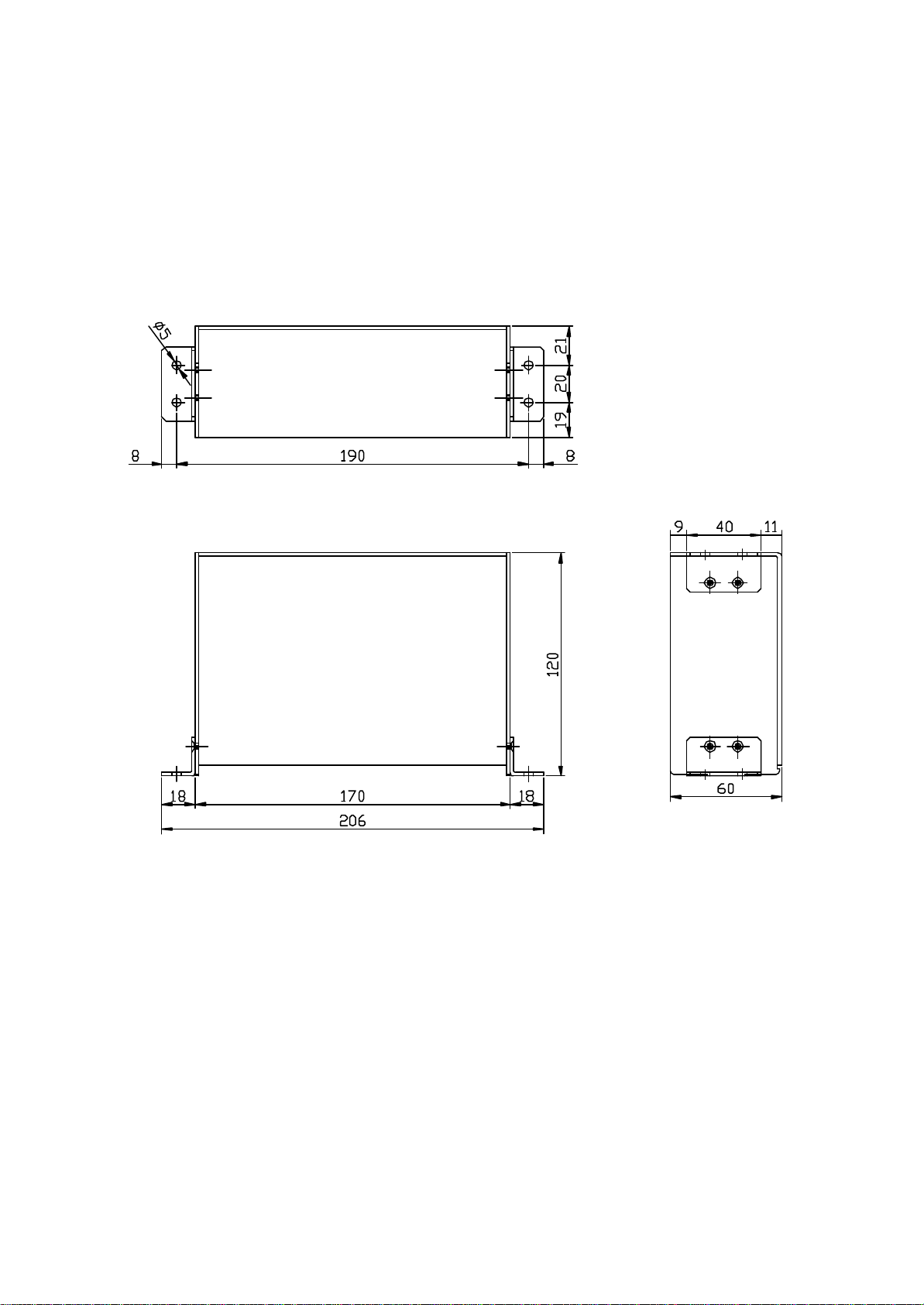
4-2 Drive dimensions
Unit : mm
9
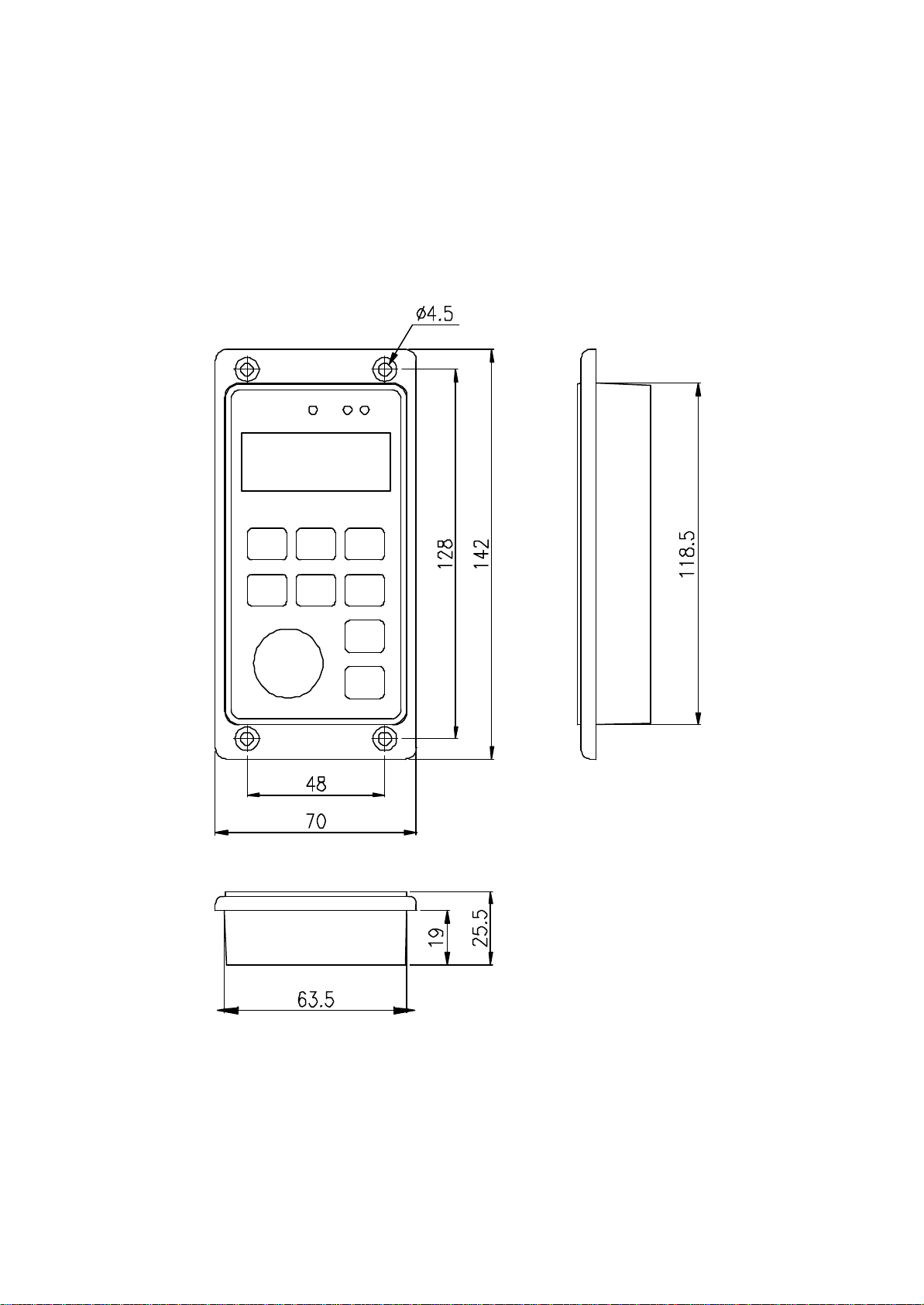
4-3 F306 dimensions
Unit : mm
10

5. Environmental requests
Operation
Storage
Transportation
Note :
a. Bad installation can reduce product service life.
b. Do not put motors and drives into worse environment. Such as
high temperature/humidity/vibration, corrosiveness gas, burst.
c. Keep enough cooling space for motors and drives.
Air temperature -20~60 (-4~140 )℃ ℉
Air pressure 86~106kPa
Humidity Less than 90%, no frosting
Air temperature -20~60 (-4~140 )℃ ℉
Air pressure 86~106kPa
Humidity Less than 90%, no frosting
Vibration Less than 20HZ : maximum 9.86m/s2
20~50HZ : maximum 5.88m/s2
11
Air temperature -10~45 (14~113 )℃ ℉
Air pressure 86~106kPa
Attitude Under 1000 meters
Vibration Less than 20HZ : maximum 9.86m/s2
20~50HZ : maximum 5.88m/s2

10cm 10cm
Motors
Drives
5cm 5cm
12

6. Function Description
6-1 Digital operation panel
FUNC
STOP
F306 FWD
CHARGE
REV
REMOTE CONTROL
FUNC
STOP
13
Keypad Function Description
Forward
run Commands forward run
Reverse
run Commands reverse run
Cursor
movement Select the digit
Down Decrease the parameter value 9~0
Up Increase the parameter value 0~9
Memory
storage Saves the setting parameter value
Function Press once to select function code and
press again to change its content
Stop Stop operation / Escape to standby mode

6-2 Terminals
14
BRUSHLESS IPM MOTOR
DRIVES
ADLEEPOWER R
Ground
Power input
Case ground
Power LED
Direction LED
Motor
Speed/error display
Fault LED
Internal speed setting
Magnet brake power
7
10
9
8
6
5
3
4
1
2
11
12
Relays, etc.
When using switches.
INT.
(Default value)
When using PLC etc.
EXT.
Command selection(Terminal, F306, RS485)
Communication port
Twist line
11 L
7 ALARM OUT
6 SPEED OUT
3
9 H
10 M 1
2
1 INPUT COM
5 SLOW DOWN
3 CW
4 CCW
2 CF
3
21
Slow down input
+24V external power input
12 GND Shielding line Speed knob (options)
C.C.W. input
C.W. input
Speed selector
ON
OFF
ON
OFF
ON
OFF
ON
OFF
EXG
EXG
EXG
Alarm output
Speed output
EXG
EXG

6-3 Main circuit terminals
15
Wire Wire type Torque
Input(L1,L2, ) 14AWG~16AWG
(2.0mm2~1.3mm2)Standard copper only
(300V/80 )℃8Kg-cm
(6.95lb-in)
External control
signal terminals 24AWG
(0.2mm2)Standard copper only
(300V/80 )℃5Kg-cm
(4.34lb-in)
FG screw (M4) 14AWG~16AWG
(2.0mm2~1.3mm2)Standard copper only
(300V/80 )℃8Kg-cm
(6.95lb-in)

6-4 Terminal description
Input source power line added 20A line fuse (or equivalent) is
recommanded for safety. Do not try to modify the wire between
motors and drives. The extension cable is available from factory.
Do not connect the shielding wires to any other component.
Make sure all plugs are tight enough with socket. Otherwise, it
may damaged the motors and drives.
: Case ground.
L, N : 100~130VAC or 200~230VAC, 50/60HZ, power input.
Power : Green LED light on when AC power input.
CW, CCW : Motors operation direction.
RPM : Static display for motor real speed (motor running).
Flash display for motor setting speed (motor stop).
Error codes, check the trouble shooting.
In “open loop control mode”, the RPM display is showing
“Duty”, not motor speed. The unit is 0.1%. Ex. 1000 is
100.0%, 999 is 99.9%.
Motor : Wires connect to motors.
There are extension cable for option as below
1M(3.28ft), 3M(9.84ft), 5M(16.4ft), 9M(29.52ft).
Motor cable should be no more than 10M(32.8ft) in
length.
Ground terminal : Wires by AWG18 (0.75mm2).
F306/RS-485 : F306 or RS-485 communication port.
JP : Control mode
F306 : Jumper on F306.
RS485 : Jumper on RS485.
Terminal : Jumper on both F306 and RS485.
Note : It needs to reset driver to effect the new JP setting.
!
█
█
█
█
█
█
█
█
█
16

Speed :
1. Close loop control mode (Default)
Motor stops operation if speed command is lower than minimum
speed.
L series : 150~2000 RPM
M series : 150~3000 RPM
H series : 300~6000 RPM
HX1 series : 130~5000RPM
HX2 series : 300~9999RPM
Default value : 0RPM
2. Open loop control mode
Motor speed is controlled by PWM duty. The duty is set by
analog signal.(0~100%) Motor speed is changed with loading.
3. Open / close loop control mode is set at CD02.
Alarm : Fault LED.
Red LED lighted when protect function effected. Please
check the error on display refer to trouble shooting.
EXT-INT : EXT : Using external control power 24VDC ±10%.
INT : Using internal control power.
Magnet brake : Connect to motors external brake, 24VDC Max.
15W.
External signal terminals :
The following terminals can be connected to a switch, relay,
TTL or Transistor for control purpose.
1. 24V in :
24VDC external control power input when using the circuit
control. The EXT-INT switch is set on EXT.
The EXT-INT switch is set at INT when using relays or
switch control.
█
█
█
█
█
●
17
●

2. CF :
Analog command mode (CD19=0)
OFF : Panel VR
ON : Terminal control (HML)
Digital command mode (CD19=1)
Close loop control
OFF : CD28 speed setting
ON : CD29 speed setting
Open loop control
OFF : CD34 speed setting
ON : CD35 speed setting
(Note : F306 does not relate to CF setting.)
3. CW : Forward operation (ON), stop(OFF).
4. CCW : Reserve operation (ON), stop(OFF).
5. S.D. : Set “ON”when using S.D. function (Dec. time)
Set “OFF”for immediately stop (without Dec.time)
6.Speed : Output motor speed
L, M, HX1 series : 12 pulse / per turn
H, HX2 series : 6 pulse / per turn
7. Alarm out : Output fault signal.
Drives output fault signal when protect function
take effect such as over load, over voltage,
overheat and so on.
Motors stop by free run.
Check detail information at trouble shooting.
8. EXG : Common terminal for external signal 2~7.
9. H : 5VDC output.
10. M : Speed voltage signal input.
11. L : Common terminal for H, M terminal.
12. GND : Connect to the shielding line for external speed
command signal.
18
█
●
█
█
█
█
█
█
█
█
●
█
█
Model Slow down signal
Start by Acc. time & stop by Dec. time ON
Start by Acc. time & stop by CD03 content OFF
This manual suits for next models
16
Table of contents
Other Adleepower DC Drive manuals

Popular DC Drive manuals by other brands

Toshiba
Toshiba G3 Plus Pack Operation manual addendum

SEW-Eurodrive
SEW-Eurodrive MAXO-RG-BMS operating manual

ABB
ABB DCS880 series Hardware manual

ABB
ABB PSTX30 Service instruction

ABB
ABB ACS880-14 Hardware manual

Cerus Industrial
Cerus Industrial Titan GS Series Installation, operation & maintenance manual


