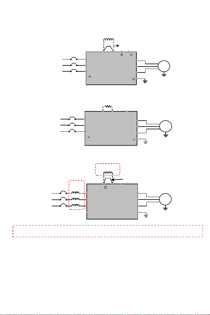
Rhymebus RM6 Series User manual

1
http://www.rhymebus.com.tw
2020.02.06 Edition
Thank you for using RHYMEBUS RM6 series drive.
For proper operations and safety purposes, please read manual carefully .
Only the qualified personnel may proceed with the installation.
Visit RHYMEBUS website: http://www.rhymebus.com.tw for complete operation manual.
Please pay attention to the safety precautions marked with “DANGER” or “CAUTION” in
complete manual before installation.
DANGER
User may cause the casualty or serious damages if user does not abide
by the instructions of the manual to execute the tasks.
CAUTION
User may cause injuries to the people or damage the equipment if user
does not abide by the instructions of the manual to execute the tasks.
Power Source
R,S
(L,N)
AC power source
input terminals
Single-phase; sinusoidal power source input terminals.
R,S,T
(L1,L2,L3)
Three-phase; sinusoidal power source input terminals.
○
+, N○
-
DC power source
input terminals
External DC power source terminal.
※Only 2007 ~ 2015, 4007 ~ 4020 models have the terminal.
Motor
U,V,W
(T1,T2,T3)
Drive outputs to
motor terminals
Output three-phase variable frequency and voltage to
motor.
Power
and Braking
P(+), N○
-
Dynamic brake unit
terminal
The terminals can connect to dynamic braking
unit(option).
P○
+, N○
-
P, N
P, PR
External
brakingresistor
terminal
The terminals can connect to external brake resistor
(option).
P(+), PR
P○
+, PR
P(+), P1
External reactor
terminal
The terminal can connect to DC reactor (DCL) for
improving power factor. The default setting is
connected by a jumper.
P○
+, P1
Grounding
PE(or G)
Grounding terminal
Ground the drive in compliance with the NEC standard
or local electrical code.
RM6 Series
Simple Version
Operation Manual
Terminals of Main Circuit

2
RM6 IM
R/L1
S/L2
W/T3
V/T2
G
U/T1
PRP N Induction Motor
T/L3
※2: Braking Resistor(option)
R/L1
S/L2
G
T/L3
Model:RM6-1001/2-1PH~RM6-1002-1PH ; RM6-2001/2-1PH~RM6-2002-1PH
Model:RM6-2001/2~RM6-2005 ; RM6-4001~RM6-4005
※Single-Phase connect to
R/L1,S/L2 terminal.
※Three-Phase connect to
R/L1,S/L2 ,T/L3 terminal.
RM6 IM
R/L1
S/L2
W/T3
V/T2
U/T1 Induction Motor
T/L3
R/L1
S/L2
T/L3
N
※2:Braking Resistor
(option) Jumper
P(+)PR P1
※1:DC Reactor(DCL; option)
RM6 IM
R/L1
S/L2
W/T3
V/T2
U/T1 Induction Motor
T/L3
R/L1
S/L2
T/L3
N
Jumper
P(+) P1
※1:DC Reactor(DCL; option)
Model:RM6-2007 ~ RM6-2015;
Model:RM6-4007 ~ RM6-4025;
Model:RM6-2020 ~ RM6-2040;
Model:RM6-4030 ~ RM6-4060
RM6 IM
R/L1
S/L2
W/T3
V/T2
U/T1 Induction Motor
T/L3
R/L1
S/L2
T/L3
N
Jumper
P(+) P1
※1: DC Reactor(DCL; option)
Three-Phase
50/60Hz AC Power Input
※2:Braking Resistor(option)
PR
Three-Phase,
50/60Hz AC Power Input
Three-Phase,
50/60Hz AC Power Input
Model(B Type):RM6-2020B ~ RM6-2040B;
Model(B Type):RM6-4030B ~ RM6-4060B
Decription of terminal and wiring diagram

3
RM6 IM
R/L1
S/L2
W/T3
V/T2
U/T1
Induction Motor
T/L3
R/L1
S/L2
T/L3
N
P
Three-Phase,
50/60Hz AC Power Input
※2:Braking Resistor(option)
Model(B Type): RM6-2050B ~ RM6-2075B;
Model(B Type): RM6-4075B ~ RM6-4175B
PR
RM6 IM
R/L1
S/L2
W/T3
V/T2
PE
U/T1
PP1 NӨ
Three-Phase,
50/60Hz AC Power Input
Induction Motor
T/L3
PE
R/L1
S/L2
T/L3
DCL
※1
ACL
Jumper
+
Model: RM6-2100~RM6-2250;
Model: RM6-4100~RM6-4600
RM6 IM
R/L1
S/L2
W/T3
V/T2
U/T1
Induction Motor
T/L3
R/L1
S/L2
T/L3
Three-Phase,
50/60Hz AC Power Input
Model: RM6-2050 ~ RM6-2075;
Model: RM6-4075
※1
N
Jumper
P(+) P1
※1:DC reactor(DCL; option)
※1.RM6-100HP above drives: AC reactor (ACL) is the standard accessory;
RM6-175HP above drives: DC reactor (DCL) is the standard accessory.
Please remove the jumper between P1 and P terminal, when connecting the external DC
reactor (DCL). Do Not remove the jumper, when DC reactor (DCL) does not be connected.
※
2.PR terminal is suitable for braking resistor and B Type Series of RM6 is optional
(Example: RM6-2020B, include braking resistor)

4
Control Termianl
Type
Symbol
Function
Description
Control circuit terminal
Control
power
P24
Power terminal;
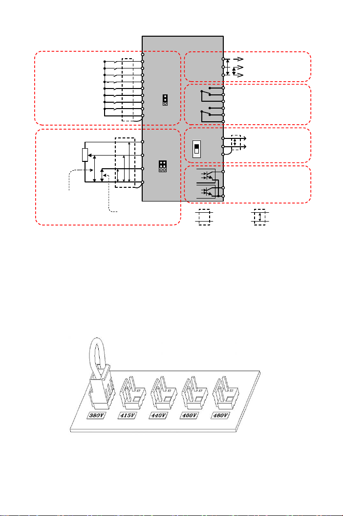
Control device usage
Output DC+24V; Maximum supplied current is 50mA.
P12/12V
Output DC+12V; Maximum supplied current is 20mA.
GND
(COM)
Common of analog input
control terminals
Common terminal for control power (P12/12V,P24) and
analog input terminal (Vin, Iin).
Input terminals
FWD
Forward command
terminal
Connect the FWD and COM terminals for forward
operation. (F_001=0,1,2)
REV
Reverse command
terminal
Connect the REV and COM terminals for reverse operation.
(F_001=0,1,2)
X1
Multi-function input
terminal 1
․The function is set by F_052.
․Default setting: Multi-speed level 1 command
X2
Multi-function input
terminal 2
․The function is set by F_053.
․Default setting: Multi-speed level 2 command
X3
Multi-function input
terminal 3
․The function is set by F_054.
․Default setting: Jog command
X4
Multi-function input
terminal 4
․The function is set by F_055.
․Default setting: Secondary accel/decel time command
X5
Multi-function input
terminal 5
․The function is set by F_056.
․Default setting: External fault command (thr)
X6
Multi-function input
terminal 6
․The function is set by F_057.
․Default setting: Reset command
COM
(GND)
Common of digital input
control terminals
Common of digital input control signal terminals. (FWD,
REV and X1 ~ X6)
Vin
Analog input terminal
Input range: DC 0~10V。
Iin
Analog input terminal
․Input signal selection
JP4: I position (current signal)
JP4: V position (voltage signal)
․Input range: DC 4~20mA (2~10V) or
DC 0~20mA (0~10V)
․The function is set by F_126.
Output terminals
FM+
AM+
Analog output terminals
․Voltage meter with 10V full scale spec.
(meter impedance: 10kΩ above)
․Maximum output current: 1mA
M-
(GND)
Common of
analog output terminals
Common of analog output terminals.
Ta1
Multi-function
output terminals
(relay type)
․N.O (contact a); The function is set by F_060 .
․Default setting: Error detection
․Capacity: AC250V, 0.5A Max, cosθ=0.3
Tb1
․N.C (contact b); The function is set by F_060
․Capacity: AC250V, 0.5A Max, cosθ=0.3
Tc1
Common terminal for Ta1, Tb1.
Ta2
․N.O (contact a); The function is set by F_131
․Default setting: Operation detection
․Capacity: AC250V, 0.5A Max, cosθ=0.3
Tb2
․N.C (contact b); The function is set by F_131
․Capacity: AC250V, 0.5A Max, cosθ=0.3
Tc2
Common terminal for Ta2.
Y1
Multi-function output
terminals
(open collector type)
․The function is set by F_058, F_059.
․Capacity: DC48V, 50mAMax
Y2
CME
Common terminal of Y1, Y2.
External
Communication
Terminal
DX+
Signal transmission
terminal(+)
․Connect the RM6 series drive by transmission cable,
when the drive is controlled by RS-485 communication
interface.
․Communication protocol: Modbus
DX-
Signal transmission
terminal(-)
GND
Grounding terminal of
signal transmission
Grounding terminal of shielding wire.

5
※1.JP5: SINK / SOURCE selection;
The signal input selection of multi-function input terminal(X1~X6), FWD/REV
terminals.
※2.JP4: I / V selection;
I position: Iin-GND terminal is inputted with the current signal.(default)
V position: Iin-GND terminal is inputted with the voltage signal.
※
3.DSW3: The terminal resistor selection for communication; The internal resistance is 100Ω.
When external device control multiple drives, switch the DSW3 to “ON”position at
the first and last drive.
※4.The analog input selection is set by F_126 (default: DC 2~10V(4~20mA))
Voltage Selection Board of Cooling Fan
Description of Terminal and Wiring Diagram
SINK
SOURCE
I
V
FWD
REV
X1
X4
X5
X6
P12
Vin
Iin
GND
(COM)
CME
Y2
Y1
Tc1
Tb1
Ta1
Tc2
Ta2
FM+
AM+
Shielded
Wire Twisted-Pair
Shielded Wire
P
P P P
VR 1KΩ,1/4W
Forward
Reverse
Multi-function Input Terminal 1 (-)
(+)
(+)
Multi-function Output Terminal
(Relay Type)
(AC 250V/0.5A COSθ=0.3)
Multi-function Output Terminal
(Open collector)
(DC 48V/50mA)
※2
M-
(GND)
Analog Output Terminal
(DC 0~10V)
※1
COM
(GND)
Analog input signal
(default: DC 4~20mA)
Analog input control
(default: DC 0~10V)
JP4
Communication Control
Terminal
P
DX+
DX-
GND
P24
JP5
ON
1
DSW3
Multi-function Input Terminal 2
Multi-function Input Terminal 3
Multi-function Input Terminal 4
※3
RM6
X2
X3 Tb2
Multi-function Input Terminal 5
Multi-function Input Terminal 6
※RM6-4075 above models have the voltage selection board shown in above figure when
removing the main circuit terminal cover of the drive. Please carefully select the jumper
position according to the power source(actual power voltage level) to avoid the burnout
of the fan or the overheating of the drive.(EX: When the power source is 460V, selecting
the position from 380V to 460V)

6
Digital Type Keypad (KP-603) for RM6
Operation of Keypad
Display panel
Blinking: Under acceleration
or deceleration
ON: Constant speed
OFF: Stop
Drive start key
Up/down key of changing
functions and parameters
1. Drive stops(cut off output
frequency of drive)
2. Fault reset
1. Enter parameter setting mode
2. Back to function setting mode
3. Switch monitor mode
1. Enter function setting mode
2. Back to monitor mode
Unit indicator
Pot knob
1. ON: Primary frequency
command is set by
keypad or UP/DOWN
terminal
2. OFF: Primary frequency
command is set by
multi-function input
terminals
The operation of the digital keypad includes fault messages and three modes. The switching
methods are shown as below figure:
Monitor mode Function setting mode Parameter setting mode
Fault message
FUN
DATA
PROG FUN
DATA
STOP
RESET
PROG
PROG
KEYPAD
Hz V A
KEYPAD
Hz V A
KEYPAD
Hz V A
KEYPAD
Hz V A *When the keypad is idle for three minutes at“function setting
mode”or“parameter setting mode”, drive will switch back to
the“main display”.
The operation steps are shown as below table (by default setting)
Operation Steps
Display
1.Start the drive and enter the monitor mode.
KEYPAD
Hz V A
2.Press
PROG
key and enter the function setting mode.
KEYPAD
Hz V A
3.Press
FUN
DATA
key and enter the parameter setting mode.
KEYPAD
Hz V A
4.Press
FUN
DATA
key and return to the function setting mode.
KEYPAD
Hz V A
5.Press
PROG
key and return to the monitor mode.
KEYPAD
Hz V A

7
Parameter List
Description of Monitor Mode
There are eight displays can be selected in the monitor mode. Press
FUN
DATA
to switch the
display in accordance with below sequence under monitor mode. User can determine one of
eight displays as the main display from function F_006 (Selection of Main Display). Please
refer to the following illustrations:
Display 1
(Output Frequency) Display 2
(Frequency Command) Display 3
(Output Voltage)
Display 5
(Output Current)
Display 6
(Motor Speed(RPM))
Monitor
Mode
Display 4
(DC Bus Voltage)
FUN
DATA
FUN
DATA
KEYPAD
Hz V A
KEYPAD
Hz V A
KEYPAD
Hz V A
KEYPAD
Hz V A
KEYPAD
Hz V A
FUN
DATA
FUN
DATA
KEYPAD
Hz V A
FUN
DATA
FUN
DATA
KEYPAD
Hz V A
KEYPAD
Hz V A
Display 7
(Machine Speed(MPM))
Display 8
(Terminal Status and
Heat Sink Temperature)
FUN
DATA
FUN
DATA
Func.
Name
Description
Range of
Setting
Unit
Default
F_000
Drive Information
0: Software version
1: Drive model number
2: Drive running hours
3: Drive supply power time
4: Software checksum code
5: Reserved
─
─
─
F_001
Start Command
Selection
Start command
Rotation direction
command
0~11
─
3
0:
FWD or REV terminal
FWD or REV terminal
1:
FWD terminal
REV terminal
2:
Keypad “RUN” key
FWD, REV terminal
3:
Forward direction
4:
Reverse direction
5~7:
Reserved
Reserved
8:
Communication
interface
Communication
interface
9:
Communication
interface
REV terminal
10:
FWD terminal
Communication
interface
11:
Keypad “RUN” key
Communication
interface
a. Select one of eight displays as the main display from function F_006 (Selection of Main
Display).
b. Determine one of eight displays as the main display according to the application. When
the parameter of function is completed without pressing key, the drive will automatically
switch back to the main display after 3 minute.

8
Func.
Name
Description
Range of
Setting
Unit
Default
F_002
Primary
Frequency
Command
Selection
0: Frequency command by analog signal via terminal.
1: Frequency command by keypad.
2: Motor speed (RPM) command by keypad.
3: Machine speed (MPM) command by keypad.
4: Frequency command by UP/DOWN terminal.
5: Frequency command by communication interface.
6: Frequency command by keypad pot.(Vin and Iin
are disable)
0~6
─
1
F_003
Selection of “STOP”
Key Validity
0: Start command by terminal, “STOP” key disabled.
1: Start command by terminal, “STOP” key enabled.
0,1
─
1
F_004
Frequency
Command Selection
0: In the monitor mode, frequency command cannot
be changed.
1: In the monitor mode, frequency command is
changeable.
0,1
─
1
F_005
Selection of
Frequency
Command
Auto-Storing
0: In the monitor mode, frequency command
auto-storing disable.
1: In the monitor mode, frequency command
auto-storing after 3 minutes.
0,1
─
1
F_006
Selection of
Main Display
When F_153=0, select 1 of 8 “monitor modes” as the
main display.
1~8
─
1
F_007
Machine Speed
Ratio
Set the ratio of machine speed. This function
determines MPM display value.
0.00~
500.00
0.01
20.00
F_008
Digits of Decimal
Value (Machine
Speed)
Select the digits of decimal values displaying the
machine speed.
0~3
─
0
F_009
Primary Speed
Multi-speed
level 4
command
Multi-speed
level 3
command
Multi-speed
level 2
command
Multi-speed
level 1
command
0.00~
400.00
0.01
Hz
50.00
(Note1)
OFF
OFF
OFF
OFF
60.00
(Note2)
F_010
Preset Speed 1
OFF
OFF
OFF
ON
10.00
F_011
Preset Speed 2
OFF
OFF
ON
OFF
20.00
F_012
Preset Speed 3
OFF
OFF
ON
ON
30.00
F_013
Preset Speed 4
OFF
ON
OFF
OFF
0.00
F_014
Preset Speed 5
OFF
ON
OFF
ON
0.00
F_015
Preset Speed 6
OFF
ON
ON
OFF
0.00
F_016
Preset Speed 7
OFF
ON
ON
ON
0.00
F_196
Preset Speed 8
ON
OFF
OFF
OFF
0.00
F_197
Preset Speed 9
ON
OFF
OFF
ON
0.00
F_198
Preset Speed 10
ON
OFF
ON
OFF
0.00
F_199
Preset Speed 11
ON
OFF
ON
ON
0.00
F_200
Preset Speed 12
ON
ON
OFF
OFF
0.00
F_201
Preset Speed 13
ON
ON
OFF
ON
0.00
F_202
Preset Speed 14
ON
ON
ON
OFF
0.00
F_203
Preset Speed 15
ON
ON
ON
ON
0.00
F_017
Jog Speed
Frequency setting by manual
6.00
F_018
Reference
Frequency of
Accel/Decel Time
The frequency corresponding to accel/decel time.
0.01~
400.00
0.01
Hz
50.00
(Note1)
60.00
(Note2)
F_019
Primary
Acceleration Time
The acceleration time of primary speed, preset speed
4~15, and jog speed.
0.0~
3200.0
0.1sec
15.0
(Note5)
F_020
Primary
Deceleration Time
The deceleration time of primary speed, preset speed
4~15, and jog speed.
F_021
Acceleration Time
of Preset Speed 1
Acceleration time of preset speed 1.
F_022
Deceleration Time
of Preset Speed 1
Deceleration time of preset speed 1.
F_023
Acceleration Time
of Preset Speed 2
Acceleration time of preset speed 2.
F_024
Deceleration Time
of Preset Speed 2
Deceleration time of preset speed 2.
F_025
Acceleration Time
of Preset Speed 3
Acceleration time of preset speed 3.

9
Func.
Name
Description
Range of
Setting
Unit
Default
F_026
Deceleration Time
of Preset Speed 3
Deceleration time of preset speed 3.
0.0~
3200.0
0.1
sec
15.0
(Note5)
F_027
Secondary
Acceleration Time
Switch to secondary acceleration time by
multi-function input terminal.
F_028
Secondary
Deceleration Time
Switch to secondary deceleration time by
multi-function input terminal.
F_029
Set S-curve for
Accel/Decel Time
Set S-curve to slow the acceleration and deceleration
time at start and stop.
0.0~5.0
0.1sec
0.0
F_030
Limitation of Output
Voltage
0: Output voltage of V/F pattern is not limited,
decrease the swithching frequency.
1: Output voltage of V/F pattern is limited, decrease
the swithching frequency.
2: The output voltage of V/F pattern is not limited.
3: The output voltage of V/F pattern is limited .
0~3
─
0
F_031
Maximum Output
Frequency
Maximum output frequency of drive.
0.1~400.0
0.1Hz
50.0
(Note1)
60.0
(Note2)
F_032
Starting Frequency
Starting frequency of drive’s output.
0.1~10.0
0.1Hz
0.5
F_033
Starting Voltage
The voltage corresponds to the output starting
frequency.
0.1~50.0
0.1V
8.0
(Note3)
0.1~100.0
12.0
(Note4)
F_034
Base Frequency
The frequency corresponds to the base voltage in V/F
pattern.
0.1~400.0
0.1Hz
50.0
(Note1)
60.0
(Note2)
F_035
Base Voltage
The voltage corresponds to the base frequency in V/F
pattern.
0.1~255.0
0.1V
220.0
(Note3)
0.1~510.0
380.0
(Note4)
F_036
V/F Frequency 1
Frequency at the first point of V/F pattern.
0.0~399.9
0.1Hz
0.0
F_037
V/F Voltage 1
Voltage at the first point of V/F pattern.
0.0~255.0
0.1V
0.0
0.0~510.0
F_038
V/F Frequency 2
Frequency at the second point of V/F pattern.
0.0~399.9
0.1Hz
0.0
F_039
V/F Voltage 2
Voltage at the second point of V/F pattern.
0.0~255.0
0.1V
0.0
0.0~510.0
F_040
Vin Gain
Analog input “Vin” gain ratio adjustment.
0.00~2.00
0.01
1.00
F_041
Vin Bias
Analog input “Vin” bias ratio adjustment.
-1.00~
1.00
0.01
0.00
F_042
Frequency Upper
Limit
The upper limit of output frequency=
F_031(Maximum Output Frequency )*F_042
0.00~1.00
0.01
1.00
F_043
Frequency Lower
Limit
The lower limit of output frequency=
F_031(Maximum Output Frequency )*F_043
0.00~1.00
0.01
0.00
F_044
Analog Output
Signal Selection
(FM+)
0:Output frequency
1:Frequency command
2:Output current
3:“Vin” analog input signal
4:“Iin” analog input signal
5:DC bus voltage
6.Output voltage
7:Hear sink temperature
0~7
─
0
F_045
Gain(FM+)
Analog output gain ratioadjustment.
0.00~2.00
0.01
1.00
F_046
Motor Overload
Protection (OL)
0: Disable
1: Overload protection for dependent cooling fan type
motor:Enabled(OL)
2: Overload protection for independent cooling fan
type motor: Enabled(OL)
0~2
─
1
F_047
Filter Setting of
Analog Input Signal
Filter the analog input signal when the frequency
command is controlled by analog input terminal.
(F_002=0).
0~255
─
20
F_048
Motor Rated Current
Set the value according to the motor rated current.
10%~150%
of drive
rated
current
0.1A
According
to the
rated
current of
motor
F_049
Motor No-Load
Current
Set the value according to the motor’s no-load
condition.
0~motor
rated
current
0.1A
1/3 motor
rated
current

10
Func.
Name
Description
Range of
Setting
Unit
Default
F_050
Motor Slip
Compensation
According to the load condition, set the compensation
for motor running at constant speed. (0.0: off)
-9.9~10.0
0.1Hz
0.0
F_051
Number of Motor
Poles
Determinate the RPM display value of monitor mode.
2~10
2P
4P
F_052
Multi-function
Input Terminal
(X1)
=0:
UP/DOWN frequency
command enter key
±1: Jog command
±2: Secondary accel/decel
time command
±3: Multi-speed level 1
command
±4: Multi-speed level 2
command
±5: Multi-speed level 3
command
±6: Reset command
±7: External fault
command(thr)
±8: Interruption of output
command(bb)
±9: Coast to stop
command(Fr)
±10: Speed tracing from the
maximum frequency
±11: Speed tracing from the
setting frequency
±12: Holding command
±13: UP command
±14: DOWN command
±15: Clear UP/DOWN
frequency command
±16: Analog input source
selection
±17: Stop command with
3-wire start/stop circuit
±18: Under close-loop
control condition
(F_153≠0), open-loop
selection.
±19: Reset the integrator at
close-loop control
condition (F_153≠0)
±20: Stop command
±21:
Multi-speed level 4
command
-21~ +21
(Note 7)
─
3
F_053
Multi-function
Input Terminal
(X2)
=0:
DC braking enable
(at stop)
4
F_054
Multi-function
Input Terminal
(X3)
=0:
Current limit enable
1
F_055
Multi-function
Input Terminal
(X4)
=0:
Selection of primary or
secondary frequency
command
(ON: secondary
frequency command)
2
F_056
Multi-function
Input Terminal
(X5)
=0:
Stop command with
3-wire start/stop circuit
(N.O; contact a)
7
F_057
Multi-function
Input Terminal
(X6)
=0:
Stop command with
3-wire start/stop circuit
(N.C; contact b)
6
F_058
Multi-function
Output Terminal
(Y1)
0: Disable
±1: Operation command detection
±2: Constant speed detection
±3: Zero speed detection
±4: Frequency detection
±5: Overload detection(OLO)
±6: Stall prevention detection
±7: Low voltage detection(LE)
±8: Braking detection
±9: Restart after instantaneous power failure
detection
±10: Restart after error condition detection
±11: Error detection
±12: Overheating detection
±13: Upper limit of feedback detection
±14: On-Off dead band detection
±15: On-Off range detection
±16: Fan detection during operation
-16 ~+16
(Note 7)
─
3
F_059
Multi-function
Output Terminal
(Y2)
2
F_060
Multi-function
Output Terminal
(Ta1,Tb1)
11
F_061
Constant Speed
Detection Range
Set the bandwidth of constant speed detection range.
0.0~10.0
0.1Hz
2.0
F_062
Frequency
Detection Range
Set the bandwidth of frequency detection range.
0.0~10.0
0.1Hz
2.0
F_063
Frequency
Detection Level
Set the frequency detection level of multi-function
output terminal.
0.0~400.0
0.1Hz
0.0
F_064
Automatic Torque
Compensation
Range
According to the load condition, adjust the output
voltage of the V/F pattern. (0.0: off)
0.0~25.5
0.1
1.0

11
Func.
Name
Description
Range of
Setting
Unit
Default
F_065
System Overload
Detection (OLO)
0: Disable
1: Enable
0,1
─
0
F_066
System Overload
Detecting Selection
0: Detection during constant speedonly
1: Detection during operation only
0,1
─
0
F_067
Output Setting after
System Overload
0: Drive keeps operation when “OLO” is detected
1: Drive trips to protection when “OLO” is detected
0,1
─
0
F_068
System Overload
Detection Level
When the output current of drive is higher than the
level (F_068 * drive’s rated current) with the duration
of F_069, the drive will trip to protection.
30%~200%
of drive
rated
current
1%
160
F_069
System Overload
Detection Time
0.1~25.0
0.1sec
2.0
F_070
Stall Prevention
Level at
Acceleration
If stall is occurred during acceleration, the motor
keeps running at constant speed. (200%: off)
30%~200%
of drive
rated
current
1%
170
F_071
Stall Prevention
Level at Constant
Speed
If the stall is occurred during constant speed, the
motor decreases the speed.(200%: off)
30%~200%
of drive
rated
current
1%
160
F_072
Acceleration Time
Setting after Stall
Prevention under
Constant Speed
Set the acceleration time after stall prevention under
the constant speed.
0.1~
3200.0
0.1sec
15.0
(Note5)
F_073
Deceleration Time
Setting for Stall
Prevention under
Constant Speed
Set the deceleration time at the stallprevention under
the constant speed.
0.1~
3200.0
0.1sec
15.0
(Note5)
F_074
Stall Prevention
Setting at
Deceleration
0: Disable
1: Enable
0, 1
─
1
F_075
DC Braking Level
Set the current level of DC braking.
0~150%
of drive
rated
current
1%
50
F_076
Time of DC Braking
after Stop
Set the time for DC braking after drive stopped.
0.0~20.0
0.1sec
0.5
F_077
Time of DC Braking
before Start
Set the time for DC braking before drive started.
0.0~20.0
0.1sec
0.0
F_078
Operation Selection
at Instantaneous
Power Failure
0: Drive cannot be restarted
1: Drive can be restarted
2: Ramp to stop
3: Drive will restart again, when the power is restored
during ramp to stop interval.
4: Drive will restart again from 0 Hz, when the power
is restored.
0~4
─
0
F_079
Voltage Level of
Ramp to Stop by
Power Failure
Set the voltage of power source for ramp to stop.
150.0~
192.0
0.1V
175.0
(Note3)
300.0~
384.0
320.0
(Note4)
F_080
Auto-restart Times
Setting of Error Trip
When the auto-restart times of error conditions
(OC,OE,GF only) reach the setting value, the drive
must be restarted manually. (0: disable)
0~16
1
0
F_081
Switching
Frequency
The setting value is higher and the motor noise is
lower.
0~6
─
1
(Note6)
F_082
Stop Mode
0: Ramp to stop
1: Coast to stop
2: Coast to stop+ DC braking
0~2
─
0
F_083
Reverse Prohibition
0: Reverse rotation allowed.
1: Reverse rotation NOT allowed.
0, 1
─
0
F_084
Jump Frequency 1
Avoid mechanical resonance point 1.
0.0~400.0
0.1Hz
0.0
F_085
Jump Frequency 2
Avoid mechanical resonance point 2.
0.0~400.0
0.1Hz
0.0
F_086
Jump Frequency 3
Avoid mechanical resonance point 3.
0.0~400.0
0.1Hz
0.0
F_087
Jump Frequency
Range
Set the range of the jump frequency 1, 2, 3.
0.0~25.5
0.1Hz
0.0
F_088
The Current Level of
Speed Tracing
When the current is higher than the “speed
tracingcurrent level”, the output frequency will trace
downward.
0~200%
of drive
rated
current
1%
150

12
Func.
Name
Description
Range of
Setting
Unit
Default
F_089
Delay Time before
Speed Tracing
Set the delay time before the speed tracing and
coast stop+ DC braking.
0.1~5.0
0.1sec
0.5
F_090
The V/F Pattern of
Speed Tracing
Set the percentage of V/F output voltage at the speed
tracing.
0~100%
1%
100
F_091
Error Record
Display the latest 5 error records.
─
─
─
F_092
Parameter Setting
Lock
0: Parameters are changeable. Maximum frequency
cannot exceed 120.0Hz.
1: Parameters are locked. Maximum frequency
cannot exceed 120.0Hz.
2: Parameters are changeable. Maximum frequency
can exceed 120.0Hz.
3: Parameters are locked. Maximum frequency can
exceed 120.0Hz.
0~3
─
0
F_093
Automatic Voltage
Regulation (AVR)
0: Disable
1: Enable
0,1
─
1
F_094
Drive Overload
(OL1)
0: Disable
1: Thermal protection
2: Current limit overload protection
3: Both 1 and 2 enable
0~3
─
3
F_095
Power Source
Set the value according to the actual power source.
190.0~
240.0
0.1V
220.0
(Note3)
340.0~
480.0
380.0
(Note4)
F_096
Holding Frequency
The drive accelerates to the holding frequency and
running at constant speed.
0.0~400.0
0.1Hz
0.5
F_097
Holding Time
Interval
The drive runs at holding frequency by constant
speed and running the time interval.
0.0~25.5
0.1sec
0.0
F_098
Grounding Fault
Protection (GF)
0: Disable
1: Enable(GF)
0, 1
─
1
F_099
External Indicator 1
Select the monitor mode of external indicator 1
0: Disable
0~10
─
1
F_100
External Indicator 2
Select the monitor mode of external indicator 2
0: Disable
0~10
─
5
F_101
External Indicator 3
Select the monitor mode of external indicator 3
0: Disable
0~10
─
2
F_102
V/F Pattern
Selection
0:Linear.
1: Energy-saving mode (auto-adjust V/F pattern
according to the load condition).
2: Square curve.
3: 1.7th power curve.
4: 1.5th power curve.
0~4
─
0
F_103
Subtracted
Frequency of
Ramp to Stop by
Power Failure
When the power failure, drive will substract the
setting value from the current frequency before ramp
to stop.
(F_078=2 or 3)
0.0~20.0
0.1Hz
3.0
F_104
Deceleration Time 1
of Ramp to Stop by
Power Failure
When the power failure, the deceleration time before
the output frequency decelerates to the turning
frequency set in F_106.
0.0~
3200.0
0.1sec
15.0
(Note5)
F_105
Deceleration Time 2
of Ramp to Stop by
Power Failure
When the power failure, the deceleration time after
the output frequency decelerares to the turning
frequency set in F_106.
0.0~
3200.0
0.1sec
15.0
(Note5)
F_106
Turning Frequency
of Ramp to Stop by
Power Failure
Set the turning frequency level of ramp to stop when
the deceleration time is switched from F_104 setting
value to F_105 setting value.
0.0~400.0
0.1Hz
0.0
F_107
Analog Frequency
Dead Band
When the noise of analog input signal is large,
appropriately increase the dead band to stabilize the
frequency command. But adjusting this function will
reduce the tuning linearity of input signal.
0.00~2.55
0.01
Hz
0.00
F_108
Digital Input
Response Time
When the pulse width of digital signal is lower than
setting time, the signal disabled.
5~16
1ms
10
F_109
Communication
Interface Selection
0: RJ-45
1: DX+ / DX-
0,1
─
1
F_110
Communication
Address
The followers use the address to send and receive
messages. (0: disable)
0~254
─
0
F_111
Communication
Baud Rate
0: 4800bps 1: 9600bps
2: 19200bps 3: 38400bps
0~3
─
1

13
Func.
Name
Description
Range of
Setting
Unit
Default
F_112
Communication
Protocol
0: 8,N,2 1: 8,E,1
2: 8,O,1 3: 8,N,1
0~3
─
1
F_113
Communication
Overtime (Cot)
When the message transmission is interrupted or
delays during communication transmission, drive
displays “Cot” message. (0.0: disable)
0.0~
100.0
0.1
sec
0.0
F_114
Communication
Overtime Disposal
0: Warning (Cot);Continue operation
1: Warning (Cot);Ramp to stop
2: Warning (Cot);Coast to stop
0~2
─
0
F_115
Control Selection of
Multi-Function
Input Terminals
0: Multi-function input terminals (X1~X6) selves
1: Multi-function input terminals (X1~X6) command
by communication interface
0,1
─
0
F_116
Fault Reset
Selection
0: Auto-restart immediately (OC,OE,GF only).
1: Auto reset from 0Hz after the setting time (F_117).
2: Auto reset from 0Hz after the setting time (F_117)
without executing error detection. (If the drive runs
over 24hrs without any error, the drive will reset
the counting number)
0~2
─
0
F_117
Error Tripping Time
Interval before
Auto-Restart
Set the error tripping time interval before drive auto
restarts when the drive trips to stop.
(F_116=2 or 3)
1~200
10sec
6
F_118
UP/DOWN
Memory Selection
0: Clear the UP/DOWN frequency command when
power failure.
1: Save the UP/DOWN frequency command at F_121
when power failure.
0, 1
─
0
F_119
UP/DOWN
Frequency
Resolution
0: 0.01Hz 1~8: x0.05Hz
9: 0.5Hz 10~250: x0.1Hz
0~250
─
0
F_120
UP/DOWN
Trigger Mode
1~5: Continuous accel./decel. when the terminal is
activated with the duration (1 ~ 5 sec).
6: Edge trigger
1~6
─
1
F_121
UP/DOWN
Frequency
Adjustment
Adjust UP/DOWN frequency by KP-603 keypad.
0.00~
400.00
0.01
Hz
0.00
F_122
Secondary
Frequency
Command Selection
0: Frequency command by analog signal via terminal.
1: Frequency command by keypad.
2: Frequency command by UP/DOWN terminal.
3: Frequency command by communication.
0~3
─
0
F_123
Analog Input
Selection
0: Vin+Iin
1: Vin-Iin
2: Iin-Vin
3: Vin or Iin(switch by multi-function input terminal).
0~3
─
0
F_124
Analog Input
Selection
(Vin)
0: Analog input gain
1: Frequency command
2: Current limit level
3: Adjust output voltage of V/F pattern
4: Feedback signal
0~4
─
1
F_125
Analog Input
Selection
(Iin)
0: Analog input gain
1: Frequency command
2: Current limit level
3: Adjust output voltage of V/F pattern
4: Feedback sugnal
0~4
─
1
F_126
Iin Range Selection
0: 4~20mA (2~10V) 1: 0~20mA (0~10V)
0,1
─
0
F_127
Gain(Iin)
The gain ratio of analog input terminal Iin.
0.00~2.00
0.01
1.00
F_128
Bias(Iin)
The bias ratio of analog input terminal Iin.
-1.00~
1.00
0.01
0.00
F_129
Analog Output
Signal Selection
(AM+)
0:Output frequency
2:Output current
4:Iin frequency command
6:Output voltage
1:Frequency command.
3:Vin frequency command
5:DC bus voltage
7:Heat sink temperature
0~7
─
2
F_130
Gain (AM+)
AM+ analog output adjustment ratio.
0.00~2.00
0.01
1.00
F_131
Multi-function
Output Terminal
(Ta2/Tc2)
The way of settings are same as multi-function output
terminals setting.(F_058 ~ F_060)
-16~+16
(Note 7)
─
1
F_132
DC Braking
Frequencyat Stop
Active frequency level of DC braking at stop.
0.1~60.0
0.1Hz
0.5
F_135
200% Current limit
0: Disable 1: Enable
0,1
─
0

14
Func.
Name
Description
Range of
Setting
Unit
Default
F_136
PID Error Gain
Set the gain for the error of PID.
0.1~8.0
─
1.0
F_137
Delay Time before
Stop
If “stop command” is activation at multi-funtion input
terminal, drive will delay the setting time before stop.
0~1200
1 sec
0
F_138
Overheating Level
Adjustment
Overheating level(OH)=setting level+85℃
0.0~25.0
0.1℃
0.0
F_139
Operation Condition
Memory
Record the last status of drive before power off.
0: Enable (F_001=2,3,4) 1: Disable
0,1
─
1
F_140
NTC Thermistor
0: Disable. 1: Enable.
0,1
─
1
F_141
Drive Overheating
Warning Selection
0: Disable
1: Warning (Ht): Continue operation.
2: Warning (Ht): Drive de-rates the switching
frequency automatically per 5 minutes.
3: Warning (Ht): Stop operation.
0~3
─
0
F_142
Drive Overheating
Warning Level
Set the warning level to prevent drive overheating.
45~85
1℃
70
F_143
Drive Overheating
Dead Band
Set the temperature dead band of F_142 and F_145.
2.0~10.0
0.1℃
3.0
F_144
Fan Control
Selection
0: Forced air: Start the fan at power ON.
1: Operation air: Start the fan at running.
2: Temperature level setting: Start the fan according
to the setting of F_145.
0~2
─
1
F_145
Temperature Level
of Fan Activation
Set the temperature level of fan activation.
25~60
1℃
50
F_146
Minimum Operation
Time of Fan
Set the minimum operation time of fan when the fan
stops.
0.1~25.0
0.1min
0.5
F_147
“SV” Value
Set the “SV” value
F_152~
F_151
0.1unit
2.0
F_148
PID Control Display
0: PV value
2: Deviation value
4: PID feedback value
1: Integration value
3: PID command value
0~4
─
0
F_149
“SV-PV” Value
Display
Main display selection(under PID control and
command by “SV” condition)
0: “PV” value 1: “SV-PV” value
0,1
─
1
F_150
PID Control
Command
0: By F_002
1: Analong frequency command controls “SV”
2: Keypad conrols “SV”
3: Communication interface controls “SV”
0~3
─
2
F_151
Upper Limit of
Transmitter
Set the value in accordance with the maximum
specification of transmitter.
-800.0~
800.0
0.1unit
10.0
F_152
Lower Limit of
Transmitter
Set the value in accordance with the minimum
specification of transmitter.
-800.0~
800.0
0.1unit
0.0
F_153
PID Control Mode
Selection
0: Open-loop operation
1: Forward control; D postposition
2: Forward control; D preposition
3: Reverse control; D postposition
4: Reverse control; D preposition
0~4
─
0
F_154
P Selection
0: P postposition 1: P preposition
0,1
─
1
F_155
Proportional Gain(P)
Set the gain for deviation adjustment.(0.0: disabled)
0.0~25.0
0.1
1.0
F_156
Integration Time(I)
Set the integration time for deviation adjustment.
(0.0: disabled)
0.0~100.0
0.1sec
2.0
F_157
Derivative Time(D)
Set the derivative time for deviation adjustment.
(0.00: disabled)
0.00~2.50
0.01
sec
0.00
F_158
Derivative Time of
Feedback
Set the derivative time for feedback signal.
0.00~2.50
0.01
sec
0.00
F_159
Integration Upper
Limitation
Set the upper limitation value of the integration.
(1.00= maximum output frequency)
0.00~1.00
0.01
1.00
F_160
Integration Lower
Limitation
Set the lower limitation value of the integration.
(1.00= maximum output frequency)
-1.00~
1.00
0.01
0.00
F_161
Integrator Initialized
Value
Set the initial value of the integration before PID
starts. (1.00= maximum output frequency)
-1.00~
1.00
0.01
0.00
F_162
PID Buffer Space
Set the buffer space of PID output value.
0~255
─
2
F_163
Feedback Signal
Filter
Filter the feedback signal.
0~255
─
10
F_164
Feedback Signal
Trip Detection
0: Disable
1: Enable (at F_126=0)
0,1
─
1

15
Func.
Name
Description
Range of
Setting
Unit
Default
F_165
Feedback Signal
Selection
0: Direct proportion signal.
1: Inverse proportion signal.
0,1
─
0
F_166
(2nd PI Control)
Active Range
2nd PI control starts when the deviation value is
within the setting range(SV±F_166) (0.0: Disable)
0.0~25.0
0.1
0.0
F_167
(2nd PI Control)
Active Time
2nd control work with the time duration and then
switching back the primary PI control. (0.0: Disable)
0.0~300.0
0.1
0.0
F_168
Proportional
Gain(P2)
Set the gain for deviation adjustment.(0.0: disabled)
0.0~25.0
0.1
1.0
F_169
Integration Time(I2)
Set the integration time for deviation adjustment.
(0.0: disabled)
0.0~25.0
0.1
2.0
F_170
Display Setting by
Open-Loop
Command
Main display selection when the drive command by
PID and executing open-loop command.
0: PV display 1: According to the value of F_006
0,1
─
0
F_171
Setting Selection by
Open-Loop
Command
Primary speed selection when the drive command by
PID and executing open-loop command.
0~3
─
1
0: Analog input terminals
2: UP/DOWN command
1: Keypad
3: Communication
F_172
Keypad Selection by
Open-Loop
Command
Command can be adjusted by keypad when the drive
control by PID and executing open-loop command.
0: Primary speed 1: “SV” value
0,1
─
0
F_174
(On-Off)
Control Selection
0: Forward control
1: Reverse control
0,1
─
0
F_175
On-Off mode
0: Disable 1: Enable
0,1
─
0
F_176
(On) Range Setting
Drive starts when the “PV” exceeds the “On” range.
-12.8~
12.7
0.1
1.0
F_177
(Off) Range Setting
Drive stops when the “PV” exceeds the “Off” range.
0.0~10.0
0.1
1.0
F_178
(On) Delay Time
After the “PV” exceeds the “On” range and lasts a
duration(F_178), drive starts.
0~250
1sec
0
F_179
(Off) Delay Time
After the “PV” value exceeds the “Off” range and lasts
a duration(F_179), drive stops.
0~250
1sec
0
F_180
(On-Off)
Accel/Decel
Time Selection
0: Primary accel./decel. time
1: Secondary accel./decel. time
0,1
─
1
F_181
(Off) Holding Time
Hold the “Off” condition with the duration.
0~240
1sec
0
F_182
Air conditioning
mode
0: Disable
1: Enable
0,1
─
0
F_183
(Air Conditioning
Mode)
Temperature
Response Time
In the air conditioning mode,the frequency is varied
according to the setting value of temperature
response time.
PV > (SV+F186) , Variation of acceleration:
(Hz/sec) = (F_184/ F183)
PV > (SV+F187),Variation of deceleration:
(Hz/sec) = (F_184/ F183)*4.
0.0~25.0
0.1sec
5.0
F_184
(Air Conditioning
Mode)
Variation Frequency
0.1~25.0
0.1Hz
2.0
F_185
(Air Conditioning
Mode)
Upper Limit Range
of Temperature
Upper limit value = “SV” value + F_185
Lower limit value = “SV” value + F_186
When the temperature is over upper limit value, drive
outputs the setting value of F_042(Frequency Upper
Limit)
When the temperature is under lower limit value,
drive outputs the setting value of F_043(Frequency
Lower Limit)
F_184~
20.0
0.1
3.0
F_186
(Air Conditioning
Mode)
Lower Limit Range
of Temperature
0~F_184
0.1
1.0
F_187
(Air Conditioning
Mode)
Holding Frequency
Level
When the operation frequency of drive is under
(F_031*F_187) and maintaining F_188 duration,
drive runs at full speed by oper-loop condition and
maintaining a duration(F_189) and then recovering
PID control.
(F_188=0: Disable)
0.00~1.00
0.01
0.50
F_188
(Air Conditioning
Mode)
Time of Holding
Frequency
0.0~25.0
0.1hr
0.0
F_189
(Air Conditioning
Mode)
Full Speed Time
0.0~25.0
0.1
min
1.0
F_190
Feedback Limit
Detection
0: Disable
1: Warning detection;Continue operation
2: Warning detection;Stop output
3: Error detection;Error trip
0~3
─
0

16
Func.
Name
Description
Range of
Setting
Unit
Default
F_191
Feedback Limit
Level
Set the physical volume according to the specification
of transmitter(refer to F_151, F_152)
-800.0~
800.0
0.1
8.0
F_192
Feedback Limit
Detection Setting
0: Detection when “PV” > F_191
1: Detection when “PV” < F_191
0,1
─
0
F_193
Feedback Limit
Detection Time
When the feedback signal exceeds the setting value
of F_191 and maintaining a duration, drive is
detection. Drive will close the detection when the
feedback signal is without the range of feedback limit.
0~2550
1 sec
300
F_194
Feedback Limit
Range Setting
0~20.0
0.1
unit
1.0
F_195
(Feedback Limit)
Condition Selection
0: Enable during operation
1: Enable full time
0,1
─
1
F_208
Filter Setting of
Keypad pot knob
Filter the input signal when the frequency command
is controlled by keypad pot knob. (F_002=6).
0~255
─
10
F_209
Keypad pot knob
Bias
Analog input “keypad pot knob” bias ratio adjustment.
0.00~1.00
0.01
0.00
F_211
Drive Duty selection
0: Heavy duty(150% OL1)1: Normal duty(120% OL1)
0,1
─
0
F_212
Parameter Display
Selection of
Parameter Lock
1: Paramerter cannot be changed after F_213 is
ocked, but it can display the setting value.
2: Paramerter cannot be changed after F_213 is
locked, but it cannot display the setting value.
0~1
─
0
F_213
Parameter Lock
Password Setting
Setting the password of parameter lock.
0~9999
1
0
F_214
Parameter Lock
Decoding Setting
Decording the password of parameter lock.
0~9999
1
─
F_215
Current Oscillation
Gain (HPF)
The setting gain of the current oscillation (16=1)
0~255
─
0
F_220
Cut frequency of
Current Oscillation
When the setting value is too high, it will make the
output current to high in light duty.
0~2000
─
400
F_221
Current Oscillation
Gain (LPF)
When the setting value is too high, it will make the
output current to high in light duty.
0~255
─
128
F_222
Upper frequency of
Current Oscillation
prevention
The function of current oscillation enable when the
output frequency is within the range of F_222 and
F_223.
0~255
Hz
25
F_223
lower frequency of
Current Oscillation
prevention
0~255
Hz
14
F_224
Default Setting
0: Disable
─
─
0
CLF: Clear fault records
dEF60: Default value of drive for 60Hz.(heavy duty)
dEF50: Default value of drive for 50Hz.(heavy duty)
SAv: Save the setting value.
rES: Restore the setting value.
rd_EE: Read the parameters from drive to Keypad
Wr_EE: Write the parameters from keypad to drive
dEFC3: Default value of constant pressure PID
control for 50Hz
dEFC4: Default value of constant pressure PID
control for 60Hz
dEFC1~dEFC6: Customize default value
PdEF60: Default value of drive for 60Hz(normal duty)
PdEF50: Default value of drive for 50Hz(normal duty)
The color as means the functions can be set during operation.
Note:
1. Default value of 50Hz.
2. Default value of 60Hz.
3. Specification of 200V series.
4. Specification of 400V series.
5. 0.5 ~ 5HP: 5sec / 7.5 ~ 30HP: 15sec / 40HP above: 30sec
6. Heavy duty: When F_081 exceeds 4, the drive must be de-rating or selecting higher capacity.
Normal duty: When F_081 exceeds 2, the drive must be de-rating or selecting higher capacity.
7.+: Represents a contact (N.O) -: Represents b contact (N.C)

17
Error Trip Messages of Drive
Display
Description
Display
Description
(EEr)
KEYPAD
Hz V A
EEPROM error
(OLO)
KEYPAD
Hz V A
System overload
(AdEr)
KEYPAD
Hz V A
A/D converter error
(thr)
KEYPAD
Hz V A
External fault
(SC)
KEYPAD
Hz V A
Fuse open
(PAdF)
KEYPAD
Hz V A
Keypad interruption
during copy
(LE1)
KEYPAD
Hz V A
Under voltage
during operation
(OH)
KEYPAD
Hz V A
Drive overheating
(OC)
KEYPAD
Hz V A
Drive over current
(OL)
KEYPAD
Hz V A
Motor overload
(GF)
KEYPAD
Hz V A
Grounding fault
(OL1)
KEYPAD
Hz V A
Drive overload
(OE)
KEYPAD
Hz V A
Over voltage
(ntCF)
KEYPAD
Hz V A
NTC thermistor sensor
fault
(no Fb)
KEYPAD
Hz V A
PID feedback
signal error
(OP)
KEYPAD
Hz V A
Over pressure

18
Warning Messages of Drive
Display
Description
Display
Description
(LE)
KEYPAD
Hz V A
Power source
under voltage
(Err_00)
KEYPAD
Hz V A
Err_00: Keypad cable
trip.(before connecting)
(bb)
KEYPAD
Hz V A
Drive output
interruption
(Err_01)
KEYPAD
Hz V A
Err_01: Keypad cable
trip.(connected)
(Fr)
KEYPAD
Hz V A
Coast to stop
(Wr_F)
KEYPAD
Hz V A
Different software
version inter-copy
(db)
KEYPAD
Hz V A
Over voltage at
stop
(PUF1)
KEYPAD
Hz V A
First time you enter
wrong
(LOC)
KEYPAD
Hz V A
Parameter locking
(PUF2)
KEYPAD
Hz V A
Second time you enter
wrong
(ULOC)
KEYPAD
Hz V A
Parameter
Password
Unlock
(PUF3)
KEYPAD
Hz V A
Third time you enter
wrong
(dtF)
KEYPAD
Hz V A
Direction command
error
(Ht)
KEYPAD
Hz V A
Drive overheat
(PrEr)
KEYPAD
Hz V A
Program fault
(OP)
KEYPAD
Hz V A
Over pressure
(Cot)
KEYPAD
Hz V A
Communication
overtime
Other manuals for RM6 Series
1
Table of contents
Other Rhymebus DC Drive manuals
Popular DC Drive manuals by other brands

Danfoss
Danfoss VLT 2800 manual

REXROTH
REXROTH Sytronix DRn 5020 operating instructions

Danfoss
Danfoss VLT AutomationDrive FC 301 Design guide

TR-Electronic
TR-Electronic MP Series user manual

Aumuller
Aumuller KS 2 Assembly and commissioning instructions

Danfoss
Danfoss VLT AutomationDrive FC 300 Programming guide