U.S. Patent No. 8,856,780
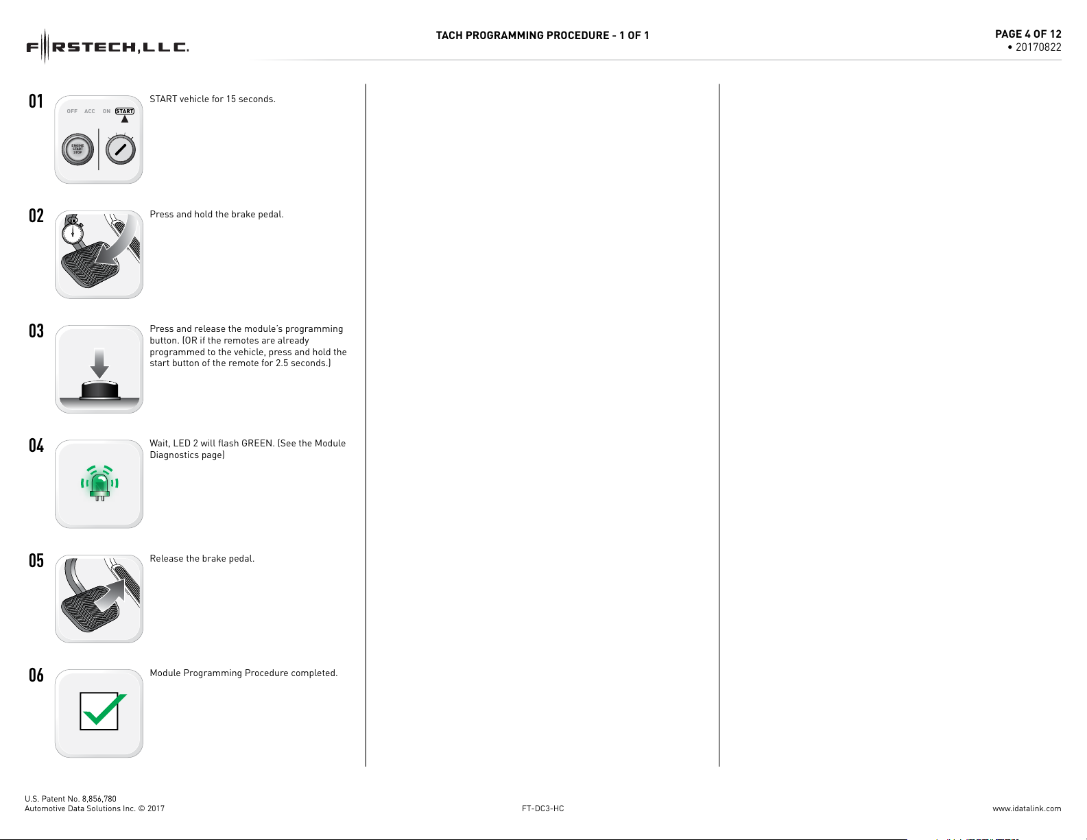
4
5
3
2
1
6
M6
FUNCTIONS DEFINED BY FIRMWARE
AUTOMATIC
TRANSMISSION
CUT LOOP
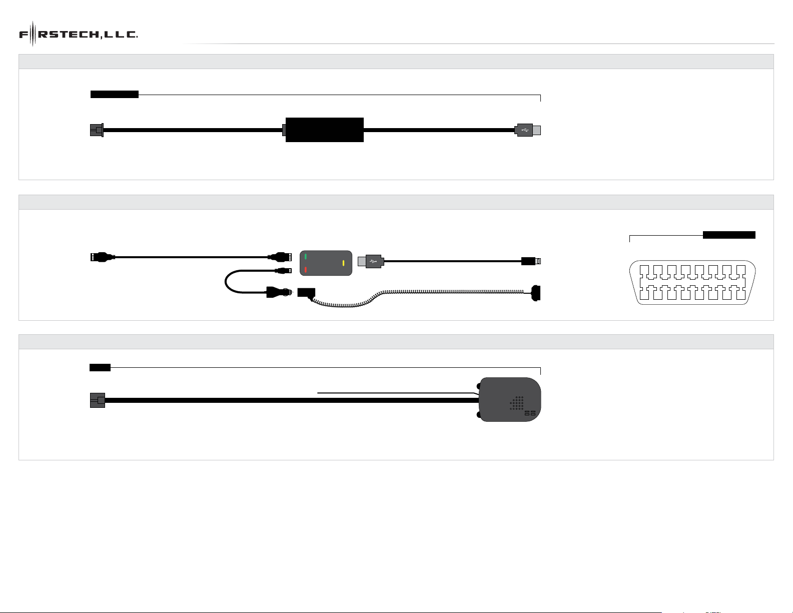
BOX CONTENTS
FT-DAS - 4 PIN RED
BLE - 4 PIN YELLOW
RF PORT - 4 PIN BLUE
DRONE - 4 PIN GRAY
M6 - 6 PIN BLACK
PROGRAMMING BUTTON
M2 - 12 PIN BLACK
M3 - 10 PIN WHITE
LED 1
LED 2
FT-DAS SENSITIVTY ADJUSTMENT DIAL
WEBLINK PORT - 4 PIN BLACK
HOOD SWITCH
STICKERS
MODULE
CM-DC3
7
9
3
10
8
6
4
1
2
5
7
9
3
10
8
11
12
6
4
1
2
5
7
9
3
10
8
11
13
14
12
15
17
18
19
20
16
6
4
1
2
5
4
5
3
2
1
6
M5
M4
01 GREEN•BLACK DOT - LOCK (-) OUTPUT
01 GREEN•BLACK DOT - LOCK (-) OUTPUT
02 BLUE•BLACK DOT - UNLOCK (-) OUTPUT
02 BLUE•BLACK DOT - UNLOCK (-) OUTPUT
03 RED/WHITE•BLACK DOT - TRUNK RELEASE (-) OUTPUT
03 RED/WHITE•BLACK DOT - TRUNK RELEASE (-) OUTPUT
04 GREEN/WHITE•BLACK DOT - ARM (-) OUTPUT
04 GREEN/WHITE•BLACK DOT - ARM (-) OUTPUT
05 GREEN/BLACK•BLACK DOT - DISARM (-) OUTPUT
05 GREEN/BLACK•BLACK DOT - DISARM (-) OUTPUT
06 BLUE/WHITE•BLACK DOT - GWR (-) OUTPUT
06 BLUE/WHITE•BLACK DOT - GWR (-) OUTPUT
07 BROWN•BLACK DOT - SIREN (+) OUTPUT
07 BROWN•BLACK DOT - SIREN (+) OUTPUT
08 WHITE/PURPLE•BLACK DOT - HORN (-) OUTPUT
08 WHITE/PURPLE•BLACK DOT - HORN (-) OUTPUT
09 PURPLE/BLACK•BLACK DOT - RAP SHUTDOWN (-) OUTPUT
09 PURPLE/BLACK•BLACK DOT - RAP SHUTDOWN (-) OUTPUT
10 WHITE/BLACK•BLACK DOT - HORN (-) OUTPUT
10 WHITE/BLACK•BLACK DOT - HORN (-) OUTPUT
11 BROWN/BLACK•BLACK DOT - GROUND WHEN ARMED (-) OUTPUT
11 BROWN/BLACK•BLACK DOT - GROUND WHEN ARMED (-) OUTPUT
12 WHITE•BLACK DOT - PARKING LIGHTS (-) OUTPUT
01 BROWN•SILVER DOT - BRAKE (+) INPUT
02 BLACK/WHITE•SILVER DOT - E-BRAKE (-) INPUT
03 PURPLE•SILVER DOT - DOOR (+) INPUT
04 GREEN•SILVER DOT - DOOR (-) INPUT
05 PURPLE/WHITE•SILVER DOT - TACH (-) INPUT
06 WHITE/BLUE•SILVER DOT - X-TRIGGER (-) INPUT
07 GRAY•SILVER DOT - HOOD (-) INPUT
08 BLUE•SILVER DOT - TRUNK (-) INPUT
09 GRAY/BLACK•SILVER DOT - GLOW PLUG (+) INPUT
10 TAN•SILVER DOT - EXT ALARM SENSOR (-) INPUT
FUNCTIONS DEFINED BY FIRMWARE
FUNCTIONS DEFINED BY FIRMWARE
M3
M2
RPS SENSOR - 4 PIN WHITE
SENSOR 2 - 4 PIN GREEN
ALARM LED - 2 PIN WHITE
TEMP SENSOR - 2 PIN BLUE
BATTERY - 2 PIN WHITE M5 - 6 PIN BLUE
M4 - 20 PIN BLACK
2X
BOX CONTENTS - 1 OF 1
M1
4
2
8
1
3
5
7
6
01 ORANGE - ACCESSORY (+)
01 ORANGE - ACCESSORY (+)
02 RED - POWER (30A)
02 RED - POWER (30A)
03 PURPLE - STARTER (+)
03 PURPLE - STARTER (+)
04 PINK/WHITE - PROG. RELAY #4 - IGNITION 2 (+) (DEFAULT)
04 PINK/WHITE - PROG. RELAY #4 - IGNITION 2 (+) (DEFAULT)
05 PINK - IGNITION (+)
05 PINK - IGNITION (+)
07 RED - POWER (30A)
07 RED - POWER (30A)
08 BLACK - GROUND
08 BLACK - GROUND
M1
06 WHITE - PROG. RELAY #5 (10A) - PARKING LIGHTS (+) (DEFAULT)
06 WHITE - PROG. RELAY #5 (10A) - PARKING LIGHTS (+) (DEFAULT)
M1 - 8 PIN BLACK
www.idatalink.comAutomotive Data Solutions Inc. © 2017 FT-DC3-HC
PAGE 3 OF 12
• 20170822