ADTRAN 239 HR Instruction Manual

61246045L1-5B Section 61246045L1-5, Issue 2 1
Section 61246045L1-5B
Issue 2, April 2000
CLEI Code # T1R6LJPD_ _
239 HRE
High-bit-rate Digital Subscriber Line Range Extender
Installation and Maintenance
Trademarks: Any brand names and product names included in this document are
trademarks, registered trademarks, or trade names of their respective holders.
1. GENERAL
This practice provides installation and maintenance
(I/M) instructions for the ADTRAN 239 T HDSL
Range Extender (HRE) (ADTRAN part number
246045L ). Figure 1 is an illustration of the HRE.
HRE equipment features include:
• Up to 12 kft of 24-gauge wire range in each
direction
• 2B1Q line coding
• Lightning protection
• In-band loopback control
• Designed for use in standard DDS or ISDN
repeater apparatus case
• Remote provisioning and pass-thru
performance monitoring
The ADTRAN 239 HRE can effectively double the
deployment range of standard HDSL and provide
Carrier Service Area (CSA)-compliant loops on
both sides of the HRE. The unit extends the digital
subscriber loop serving range up to 36 kft over
24-AWG twisted wire.
The HRE is used in conjunction with any span
powering T HDSL transceiver unit for the central
office (HTU-C) and any Low Voltage HDSL
transceiver unit for the remote end (HTU-R ).
Compatible ADTRAN HDSL transceiver units are
as follows:
Figure 1. ADTRAN 239 HRE
1246045L1
239HRE
LP1
LP2
LP1
LP2
LL
(Y)
N
E
T
C
U
S
T
RL
(G)
CONTENTS
. GENERAL ..........................................................
2. INSTALLATION ................................................ 2
3. FACEPLATE FEATURES ................................. 3
4. DEPLOYMENT GUIDELINES ......................... 3
5. MAINTENANCE ................................................ 3
6. SPECIFICATIONS ............................................. 6
7. WARRANTY AND CUSTOMER SERVICE.... 7
Appendix A. HDSL Loopbacks ......................... A-
FIGURES
Figure . ADTRAN 239 HRE ................................
Figure 2. CSA Deployment Guidelines ................. 6
Figure A- . HDSL Loopback Points .................. A-
Figure A-2. HDSL Element State Diagram ....... A-2
TABLES
Table . Telecommunications Codes ..................... 2
Table 2. Card Edge Pin Assignment ...................... 3
Table 3. 239 HRE Capacity Guidelines ................. 4
Table 4. LED Indicators ......................................... 5
Table 5. LED Operation During Standard/
Enhanced Loopbacks ............................... 6
Table 6. Loop Insertion Loss Data ......................... 6
Table 7. ADTRAN 239 HRE Specifications ......... 7
Table A- . HDSL Standard Loopback Control
Codes ................................................ A-3
Table A-2. HDSL Loopback Control Codes ...... A-4
Table A-3. Inband Addressable Loopback
Codes ................................................ A-7

2 Section 61246045L1-5, Issue 2 61246045L1-5B
Table 1. Telecommunications Codes
Part Number Unit Name
1242002LX ..... 220/E220 HTU-C
1242016LX ..... 3192 HTU-C
1242023LX ..... DDM Plus HTU-C
1244001LX ..... 4th Generation 220/E220
HTU-C
1244021LX ..... 4th Generation T400 HTU-R
CP
1244022LX ..... 4th Generation T400 HTU-R
SA
1245001LX ..... 5th Generation 220/E220
HTU-C
1245021LX ..... 5th Generation T200 HTU-R
CP
1245022LX ..... 5th Generation T200 HTU-R
SA
1245003LX ..... 5th Generation DDM and
HTU-C
1245004LX ..... 5th Generation 3192 HTU-C
1245026LX ..... 5th Generation T200 HTU-R
1245002LX ..... Litespan AHT1U
1245024LX ..... T400 HTU-R
1246001LX......6th Generation 220/E220 HTU-C
1246003LX......6th Generation DDM+ HTU-C
1246004LX......6th Generation 3192 HTU-C
1246026LX......6th Generation T200 HTU-R
There are no manual option settings on the HRE.
HRE operating power is derived from an HTU-C,
independent of line impedance or wire gauge. The
operating power from the HTU-C is also used to
span power the Low Voltage HTU-R.
The HRE operates at line losses up to 35 dB at 96
kHz, in both directions from the extender and
regenerates the 2B Q signals to meet the
transmitted power spectrum of Bellcore
TA-NWT-000 2 0.
Revision History
This revision is provided to correct Table 4. LED
Indicators.
2. INSTALLATION
Remove the ADTRAN 239 HRE from the carton
and visually ensure that damage has not occurred
during shipping or handling. If damage has
occurred, file a claim with the carrier, then contact
ADTRAN. See Warranty and Customer Service
(subsection 7 of this practice).
The ADTRAN 239 HRE is shipped in a separate
carton and must be installed in an environmental
apparatus case.
Electrical Code Compliance
Table 1 shows the Telecommunications Codes for
the 239 HRE. The 239 HRE complies with the
requirements covered under UL 950 third edition
and is intended to be installed in an enclosure with
an Installation Code (IC) of “B” or “E.”
NOTE:
This product is intended for installation in
Restricted Access Locations only.
C A U T I O N
C A U T I O N
!
SUBJECT TO ELECTROSTATIC DAMAGE
OR DECREASE IN RELIABILITY.
HANDLING PRECAUTIONS REQUIRED.
Code Input Output
IC A -
TC X X
PC C C
When installing the ADTRAN 239 HRE, refer to
the ADTRAN Installation/Maintenance practice for
the housing being used.
All connections are made through card edge
connectors. Table 2 gives the card edge pin
assingments.
NOTE:
Ensure that the chassis groungd is securly
connected to apparatus case. Ground pin
designations are defined in Table 2.
The ADTRAN 239 HRE is designed for installation
in a prewired apparatus case, and the capacity
guidlines for deployment are defined in Table 3.

61246045L1-5B Section 61246045L1-5, Issue 2 3
niPnoitangiseDnoitpircseD
1DNGdnuorG
2CNtcennoCoN
31TpiT1pooLremotsuC
41RgniR1pooLremotsuC
51TpiT1pooLkrowteN
61RgniR1pooLkrowteN
7CNtcennoCoN
8T piT2pooLkrowteN
9R gniR2pooLkrowteN
01DNGdnuorG
11T piT2pooLremotsuC
21R gniR2pooLremotsuC
Table 2. Card Edge Pin Assignment
NOTE:
These capacity guidelines were generated
through extensive testing per Bellcore
guidelines GR-487-CORE, requiring units
to operate normally at ambient
temperatures up to 47°C, with solar
loading.When installing the ADTRAN 239
HRE, refer to the ADTRAN Installation/
Maintenance practice for the housing being
used.
CAUTION:
For use in other housings, the HRE
dissipates a maximum of 3.5 watts.
The ADTRAN 239 HRE is designed for deployment
using any 239-type repeater case. A retainer patch
is available for use with the 239 HRE for securing
into the ADTRAN apparatus cases.
3. FACEPLATE FEATURES
The ADTRAN Low Voltage HRE faceplate has five
LEDs indicating diffrent states of the HDSL circuit.
Table 4 and 5 explains the meaning of the diffrent
LED indicators.
4. DEPLOYMENT GUIDELINES
The ADTRAN HDSL system is designed to provide
DS based services over loops designed to comply
with Carrier Service Area (CSA) guidelines. CSA
deployment guidelines are given below.
1. All loops are non-loaded only.
2. For loops with 26-AWG cable, the maximum
loop length including bridged tap lengths is 9
kft.
3. For loops with 24-AWG cable, the maximum
loop length including bridged tap lengths is
12 kft.
4. Any single bridged tap is limited to 2 kft.
5. Total bridged tap length is limited to 2.5 kft.
6. The total length of multi-gauge cable
containing 26-AWG cable must not exceed:
12 - {(3*L26)/(9-LBTAP)} (in kft)
L26 = Total length of 26-AWG cable
excluding bridged taps (in kft)
LBTAP= Total length of all bridged taps
(in kft)
This deployment criteria is summarized in the chart
shown in Figure 2.
Recommended maximum local loop loss
information for PIC cable at 70°F, 35Ω, resistive
termination is provided in Table 6.
An approximation for the maximum amount of
wideband noise on a DSL local loop as measured by
a 50 kbps filter is ≤ 3 dBrn.
An approximation for the maximum level of
impulse noise as measured using a 50 kbps filter on
an DSL loop is ≤ 50 dBrn.
These approximations are to be used as guidelines
only and may vary slightly on different loops.
Adhering to the guidelines should produce
performance in excess of 0-7 BER.
5. MAINTENANCE
The ADTRAN 239 HRE requires no routine
maintenance. In case of equipment malfunction,
perform an in-band loopback from the central office
(CO), as defined in Appendix A. If a malfunction
is confirmed, replace the unit.
The ADTRAN 239 HRE has looping capability
through the channel allowing digital loopback in
fault isolation. The looping is accomplished
remotely as defined in Appendix A of this practice.

4 Section 61246045L1-5, Issue 2 61246045L1-5B
Table 3. 239 HRE Capacity Guidelines
Service Capacity (Units)
Description Part Number CLEI Code Slots Material Stub Mechanics Above Ground Below Ground
ADTRAN 1150027L1 DDMOABA1MA Stainless Air-core
239/439 1150027L2 DDMOBBA1MA 4 Steel Dome Gel-filled 239/439 4 4
ADTRAN 1152010L4 DDMOBAO1MC Valox Air-core
239/439 1152010L3 DDMOBAO1MC 2 Plastic Gel-filled 239/439 2 2
ADTRAN 4-slot 1150057L1 DDMODAO1RA Stainless Air-core 4
Universal 1150057L2 DDMOCAO1RA 4 Steel Gel-filled 239/439/819 Vertical stub down only 4
ADTRAN 8-slot 1150058L1 DDMOEEO1RA Stainless Air-core 6
Universal 1150058L2 DDMOFEO1RA 8 Steel Gel-filled 239/439/819 Vertical stub down only 8
ADTRAN 1190816L1 Stainless Air-core 239/439
16-slot 1190816L2 TBD 16 Steel Gel-filled (no 819A) TBD 16
AT&T, Keptel &
ABACON 25-slot 819 25 Polymer 239/819A 12 16*
SPC 7130-0656P-TA†DDMOKJOARA Stainless Air-core 239/439 5
6-slot 7130-0656P-TB2# DDMOLJOARA 6 Steel Gel-filled (no 819A) Vertical stub down only 6
SPC 7130-V856P-TQA†DDMOKKOARA Stainless Air-core 239/439 7
8-slot 7130-V856P-TQB2# DDMOLKOARA 8 Steel Gel-filled (no 819A) Vertical stub down only 8
Keptel 8
8-slot 820 8 Polymer 239 Vertical stub down only 8
AT&T/Keptel
12-slot 809 12 Polymer 239 6 N/A
Lucent Cabinet
100-slot 841C 100 239 42 N/A
Note:
* 16 units can be loaded inside the 819 housing for all below-ground mounting orientations. If the 819 housing is mounted specifically in the virtical, stub down direction, 18 units can be loaded in slots 1, 3, 5, 7, 8, 10, 12, 13, 14, 15, 17, 18, 19, 20, 21, 22, 24, 25.
1234
57
8
12 4
578
1
3
5
7
9
11
14
6
2
3
1, 4,
7, 8,
11, 14,
15, 17,
19, 20,
23, 25
1, 3, 5, 7, 8, 10,
12, 14, 15, 16, 18,
19, 20, 22, 24, 25
1, 3,
5, 7,
9, 11
Shelf 1: 1, 3, 5, 7, 9, 11
Shelf 2: 1, 3, 5, 7, 9, 11, 14,
16, 18, 20, 23, 24,
Shelf 3: 1, 3, 5, 7, 9, 11, 14,
16, 18, 20, 22, 24
Shelf 4: 1, 3, 5, 7, 9, 11, 14,
16, 18, 20, 22, 24

61246045L1-5B Section 61246045L1-5, Issue 2 5
Table 4. LED Indicators
Five tricolored faceplate LEDs indicate these HRE states.
LED Des riptions and Indi ations
NET LP .................. This LED indicates the HDSL signal quality and errors on NET loop . The NET LP LED will flash
once when an errored second is detected on NET loop . If the NET LP LED flashes yellow rapidly
(six times per second), sealing current is present and the HRE is attempting to synchronize with the
other HDSL circuit elements.
Off .......... No synchronization with the HTU-C.
Green ...... Synchronized with good signal quality on NET loop (> 2 dB margin).
Yellow .... Synchronized with marginal signal quality on NET loop ( to 2 dB margin).
Red ......... Synchronized with poor signal quality on NET loop (0 dB margin).
NET LP2 .................. This LED indicates the HDSL signal quality and errors on NET loop 2. NET LP2 LED will flash once
when an errored second is detected on NET loop 2.
Off .......... No synchronization with the HTU-C.
Green ...... Synchronized with good signal quality on NET loop 2 (> 2 dB margin).
Yellow .... Synchronized with marginal signal quality on NET loop 2 ( to 2 dB margin).
Red ......... Synchronized with poor signal quality on NET loop 2 (0 dB margin).
CUST LP ................ This LED indicates HDSL signal quality, loopback status, and errors on CUST loop . It will flash
once when an errored second is detected on CUST loop .
Off .......... No synchronization with the HTU-R.
Green ...... Synchronized with good signal quality on CUST loop (> 2 dB margin).
Yellow .... Synchronized with marginal signal quality on CUST loop ( to 2 dB margin).
Red ......... Synchronized with poor signal quality on CUST loop (0 dB margin).
CUST LP2 ................ This LED indicates HDSL signal quality and errors on CUST loop 2. It will flash once when an
errored second is detected on CUST loop 2.
Off .......... No synchronization with the HTU-R.
Green ...... Synchronized with good signal quality on CUST loop 2 (> 2 dB margin).
Yellow .... Synchronized with marginal signal quality on CUST loop 2 ( to 2 dB margin).
Red ......... Synchronized with poor signal quality on CUST loop 2 (0 dB margin).
LL ...................................... Local Loopback. Indicates loopback from the HRE toward the network is active.
RL ...................................... Remote Loopback. Indicates loopback from the HRE toward the customer is active.
Loopback control codes are governed by the HTU-C (and HRE(s) if deployed). Standard or Enhanced loopback codes are
used dependent on the type of HTU-C deployed. See Appendix A for a more detailed description of Standard and Enhanced
loopback coding.
Note: If the signal quality is good and the pulse attenuation is bad, the LED will blink green. If the signal
quality is marginal and the pulse attenuation is good, the LED will be solid Yellow.
1246045L1
239 HRE
LP1
LP2
LP1
LP2
LL
(Y)
N
E
T
C
U
S
T
RL
(G)

6 Section 61246045L1-5, Issue 2 61246045L1-5B
Table 5. LED Operation During Standard/Enhanced Loopbacks
LED Des riptions and Indi ations
Standard Operation:
NET LP and LP2 .... Both of these LEDs will remain solid when an HRE network loopback is active.
CUST LP and LP2 . Both of these LEDs will go Off when an HRE network loopback is enabled, and will come
back On after the unit has synchronized with the HTU-C.
LL/RL ....................... This LED will be yellow when an HRE network (local) loopback is active. HRE customer
(remote) loopback is not available when using Standard Loopback code.
Enhan ed Operation:
NET LP and LP2 .... Both of these LEDs will remain solid when an HRE network or customer loopback is active.
CUST LP and LP2 . Both of these LEDs will remain solid when an HRE network or customer loopback is active.
LL/RL ....................... This LED will be yellow when an HRE network (local) loopback is active. The LED will be
green when an HRE customer (remote) loopback is active.
Figure 2. CSA Deployment Guidelines
0
12
11
10
9
8
7
6
5
4
3
2
1
0
1234
WORKING LENGTH OF 26 GAUGE CABLE (KFT)
WORKING LENGTH OF 24 GAUGE (OR COARSER) CABLE (KFT)
56789
2.5 2.0 1.5 1.0 0.5 0.0
TOTAL
BRIDGED
TAP
LENGTH
(KFT)
VALID CSA CABLE LENGTHS
INVALID CSA CABLE LENGTHS
Performance monitoring, diagnostics, and loopbacks
are also available from the craft interface at the
HTU-C and HTU-R.
When testing indicates a faulty circuit pack, refer to
the housing installation/maintenance practice for the
entry and pressurization control, then replace the
faulty circuit pack.
An in-band loopback test can be performed from the
central office (see Appendix A of this practice).
ADTRAN does not recommend field repair of this
unit. Repair services may be obtained by returning
the defective unit to the ADTRAN Customer and
Product Support (CAPS) Department.
6. SPECIFICATIONS
Specifications for the ADTRAN 239 HRE are
detailed in Table 7.
Table 6. Loop Insertion Loss Data
Frequen y (Hz) Maximum Loss (dB)
3000..................................... 2.0
0,000.................................. 5.0
50,000..................................25.5
00,000................................30.0
50,000................................32.75
200,000................................35.25

61246045L1-5B Section 61246045L1-5, Issue 2 7
Table 7. ADTRAN 239 HRE Specifications
Loop Interfa e:
Modulation Type ................ 2B Q
Mode ................................... Full duplex, echo cancelling
Number of Pairs.................. Two
Bit Rate ............................... 784 kbps per pair
Baud Rate ........................... 392K baud per pair
Service Range ..................... Defined by CSA guidelines
Loop Loss ........................... 36 dB maximum @ 200 kHz
Bridged Taps ...................... Single taps < 2 kft, total taps < 2.5 kft
Performance ........................ Compliant with Bellcore TA-NWT-00 2 0
Return Loss......................... 20 dB (40 kHz to 200 kHz)
HDSL Tx Signal Level ....... 3.5 dBm
Input Impedance ................. 35Ω
DS Channelization ............ Channels - 2 on Loop , Channels 3-24 on Loop 2
Power:
Input Power ........................ Span-powered by HTU-C: 3.5 watts, maximum
Tests:
Diagnostics ......................... Loopback initiated with HDSL in-band codes or from HTU-C or HTU-R
craft interface.
Self-test initiated from the HTU-C or HTU-R.
Physi al:
Dimensions ......................... 0.7 9" x 2.625" x 6.5"
Weight ................................ < lb.
Environment:
Temperature ........................ Operating (Standard): -40°C to +70°C; Storage: -40°C to +85°C
Relative Humidity .............. Up to 95%, non-condensing
7. WARRANTY AND CUSTOMER SERVICE
ADTRAN will replace or repair this product within
0 years from the date of shipment if it does not
meet its published specifications or fails while in
service (see ADTRAN Carrier Networks Equipment
Warranty, Repair, and Return Policy and
Procedure, document 60000087- 0A).
Contact Customer and Product Services (CAPS)
prior to returning equipment to ADTRAN.
For service, CAPS requests, or further information,
contact one of the following numbers:
Part Number
246045L
ADTRAN Sales
Pricing/Availability
(800) 827-0807
ADTRAN Technical Support
Presales Applications/Postsale Technical Assistance
(800) 726-8663
Standard hours: Monday-Friday, 7 a.m.-7 p.m. CST
Emergency hours: 7 days/week, 24 hours/day
ADTRAN Repair/CAPS
Return for Repair/Upgrades
(256) 963-8722
Repair and Return Address
ADTRAN, Inc.
CAPS
90 Explorer Boulevard
Huntsville, Alabama 35806-2807

A-1Section 61246045L1-5, Issue 261246045L1-5B
This Appendix describes the use and operation of
loopback control code sequences used in
ADTRAN’s HDSL system.
Loopback control codes are governed by the HTU-C
(and HRE(s) if deployed). Two types of HTU-Cs
exist which enable two different sets of loopback
codes: Standard or Enhanced loopbacks. The
Standard loopbacks are those that have been
contained in ADTRAN’s HDSL product family
beginning with 2nd Generation products. The
Enhanced loopbacks are contained in selected
ADTRAN HTU-C units. The following table
denotes whether the HTU-C (part number) contains
Standard or Enhanced loopback capabilities.
Standard Loopba k
Part Number Description
242002Lx............. 220/E220 HTU-C
2420 6L ............. 3 92 HTU-C
242023L ............. DDM+ HTU-C
24400 L ............. E220/220 Low Voltage
T HTU-C
244002L - L3 ..... Litespan AHDSL
244002L4 - L6 ..... Litespan AHT U
24500 L -L2 ....... E220/220 Low Voltage
5th Gen HTU-C
245003L -L2 ....... DDM+ 5th Gen HTU-C
245004L -L2 ....... 3 92 5th Gen HTU-C
Enhan ed Loopba k
Part Number Description
24500 L4-L8 ....... E220/220 HTU-C
245002L6............. Litespan AHT U
245003L4-L8 ....... DDM+ HTU-C
245004L4-L8 ....... 3 92 HTU-C
24600 L4-L8........E220/220 HTU-C
246003L4-L8........DDM+HTU-C
246004L4-L8........3 92 HTU-C
The HREs and HTU-Rs’ loopback capabilities are
controlled from the central office unit (HTU-C).
NOTE:
If the HTU-C on a circuit contains Standard
loopbacks, then refer to subsection 1 of this
Appendix to determine its capabilities. If
the HTU-C on a circuit contains Enhanced
loopbacks, then refer to subsection 2 of this
Appendix to determine its loopback
capabilities.
A-1. STANDARD LOOPBACKS
This subsection describes operation of the HDSL
system in detection of in-band and ESF facility data
link loopback codes. The operation of the loopback
commands in the ADTRAN HDSL system is
compliant with the recommendation to ANSI
recorded in T E .4/92. The HDSL network
loopback points described below are shown in
Figures A-1 and A-2.
HTU-C loopback is a regenerative loopback of the
DSX- signal toward the network.
HTU-R loopback is a regenerative loopback of the
DS signal toward the network. This loopback is in
addition to a separate Smartjack loopback. Separate
activation sequences are provided for the HTU-R
and the Smartjack loopback initiation. The HDSL
loopbacks are implemented such that the
downstream HDSL elements (toward the customer)
remain synchronized.
Figure A-1. HDSL Loopback Points
HTU-C HTU-R NIU
HRE #1
DSX-1
Interface
HDSL
Loops
HDSL
Loops
DS1
Interface
HRE #2
Appendix A
HDSL Loopbacks

A-2 Section 61246045L1-5, Issue 2 61246045L1-5B
Upon deactivation of a loopback, the HDSL system
will synchronize automatically. It should be noted
that the synchronization process of the HDSL system
upon deactivation of the HRE loopback, could take up
to 5 seconds to ensure all system elements are
synchronized.
Loopback Process
In general, the loopback process for the HDSL system
elements is modeled on the corresponding DS system
process. Specifically, the HTU-C loopback is similar
to an intelligent office repeater loopback and the
HTU-R loopbacks are similar to an inline T repeater
loopback.
Each HDSL system element is independently
described by the state diagram shown in Figure A-2.
The four states are disarmed, loop-up, armed, and
loop-up/timeout-disable.
State transitions result from in-band, ESF data link
sequences, and timeout operations. The sequences
and timeouts are as follows:
Figure A-2. HDSL Element State Diagram
ACTIVATION LOOP-UP
TIMEOUT
ARMING
TIMEOUT
DEACTIVATION DISARM
LOOP-UP
TIMEOUT
DISABLE*
*The Loop-up Timeout Disable function is currently not supported.
LOOP-UP / TIMEOUT
STATE
ARMED
STATE
LOOP-UP / NO TIMEOUT
STATE
DISARMED
STATE
•Arming (in-band and ESF)
•Activation
•Deactivation
•Disarming (in-band and ESF)
•Loop-up Timeout
•Arming Timeout
A summary of timeout and control sequences is
given in Table A-1 and A-2.
In-band control code sequences are transmitted
over the DS link by either the unframed or
overwrite method. The HDSL elements respond
to either method.
The unframed method produces periodic control
sequences, and the normal DS framing bit is
omitted.
The overwrite method produces periodic control
sequences. However, once per frame, the framing
bit overwrites one of the bits in the control
sequence.

A-3Section 61246045L1-5, Issue 261246045L1-5B
The unit can detect the loopback activation or
deactivation code sequence only if an error rate of
E-03 or better is present.
NOTE:
In all control code sequences presented, the
in-band codes are shown leftmost bit
transmitted first, and the ESF data link
codes with rightmost bit transmitted first.
Disarmed State
The disarmed state is the normal mode of operation.
Each HDSL element is transparent to the data flow.
However, the in-band data flow and the ESF data
link are monitored for the arming sequence.
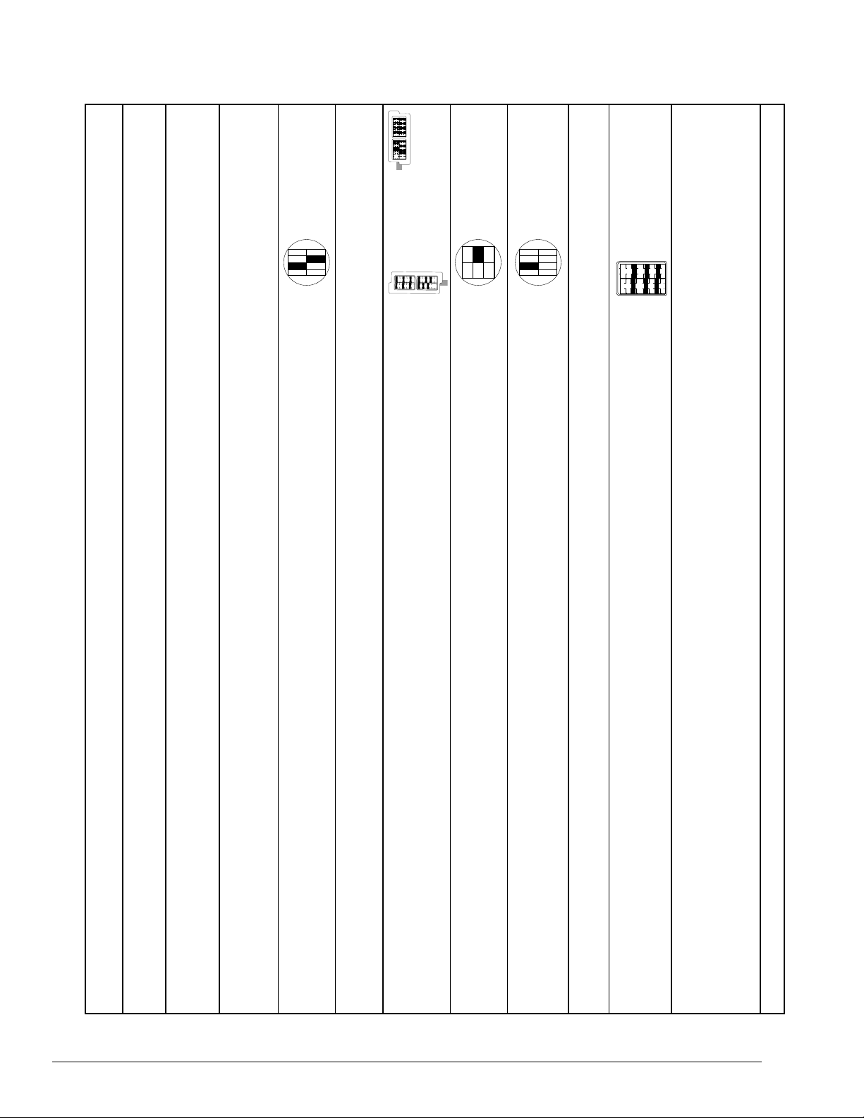
The in-band control code sequence used to
simultaneously arm the loopback capability of all
HDSL elements is the standard 5-bit in-band
sequence used for NIU Smartjack loop-up. Each
HDSL element arms after receiving the following
code for five seconds:
Arm Sequence
11000
The arming process ensures unambiguous race-free
operation of HDSL element arming and Smartjack
loop-up. The HDSL unit can detect the sequence
without interfering with the detection by the
Smartjack. Presently, the Smartjack loop-up
response requires a duration of at least five seconds.
The objective of the HDSL detection scheme is to
arm the HDSL elements without interfering with the
Smartjack loop-up.
The requirement imposed on the arm sequence is
that the Smartjack should loop-up and all HDSL
elements make a transition from the disarmed state
into the armed state. All other control code
sequences are ignored in the disarmed state.
The ESF data link sequence used to simultaneously
arm the loopback capability of all HDSL elements is
the standard 6-bit ESF data link sequence used for
NIU Smartjack loop-up.
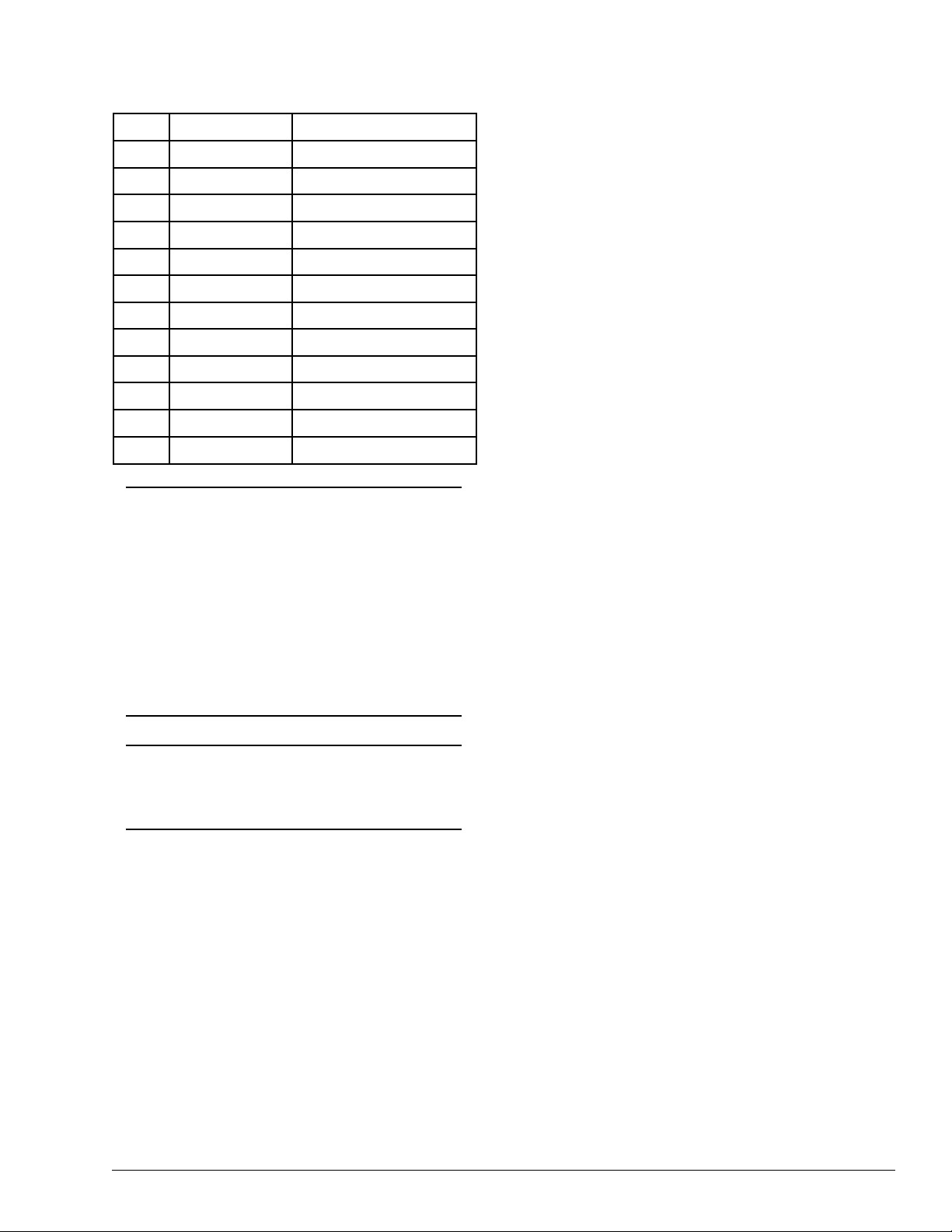
Table A-1. HDSL Standard Loopback Control Codes
Name
Arming (In-band) ...............................
Arming (ESF) .....................................
Activation (HTU-C) ..........................
Activation (HRE # ) ..........................
Activation (HRE #2) ..........................
Activation (HTU-R) ...........................
Deactivation (all HDSL elements) ....
Disarming (In-band) ..........................
Disarming (ESF) ................................
Arming Timeout .................................
Loop-up Timeout ...............................
Dete tion Time
5 Seconds
4 Repetitions
> 4 Seconds
> 4 Seconds
> 4 Seconds
> 4 Seconds
>5 Seconds
5 Seconds
4 Repetitions
2 Hours
Programmable from HTU-C:
None, 20, 60, or 20 minutes
Code
000 ...............................
000 00 0 .....
0 00 0 00 .....
00 0 0 00 000 .....
00 0 0 0 0 00
00 0 0 00 00 0 .....
00 00 00 00 .....
00 ...............................
00 0 0 00 .....
N/A ..................................
Comments
Signal sent in-band or over ESF
data link. HDSL elements in
disarmed state make transition to
armed state. Detection of either
code results in Smartjack loop-up,
if NIU loopback is enabled.
Signal sent in-band. HDSL
elements in armed state make
transition to loop-up state.
Loop-up state timeout is
programmable from the HTU-C.
Signal sent in-band. HDSL
element in loop-up state makes
transition to armed state.
Signal sent in-band or over ESF
data link. HDSL elements in any
state make transition.
HDSL elements in armed state
make transition to disarmed state.
HDSL element in loop-up makes
transition to armed state.

A-4 Section 61246045L1-5, Issue 2 61246045L1-5B
ESF Arm Sequence
0001 0010 1111 1111
for four repetitions
Race-free operations of the HDSL element arming
and Smartjack loop-up is accomplished as described
for the in-band code. For example, the ESF arm
sequence causes the Smartjack to loop-up and all of
the HDSL elements to move from the disarmed state
into the armed state. All other ESF data link control
code sequences are ignored in the disarmed sate.
Armed State
In the armed state, the HDSL system element
continues to be transparent to data flow. However,
the in-band data flow is monitored for the activation
and disarming sequences. The ESF data link is
monitored for the disarming sequence.
All other in-band and ESF data link control code
sequences are ignored in the armed state. An
arming timeout value causes automatic return to the
disarmed state.
Transition from Armed to Loop-up State
An in-band control code sequence is used to
command a specific HDSL element to move from
the armed state into the loop-up state. Each HDSL
element has a unique 6-bit activation control code
sequence as shown in the following example:
HTU-C Activation Sequence
101 0011 1101 0011
HTU-R Activation Sequence
1100 0111 0100 0010
The designated HDSL element will loop up after
receiving the proper activation sequence.
Transition from Armed to Disarmed State
All HDSL elements can be commanded to move
from the armed state into the disarmed state by the
standard 5-bit in-band disarming sequence used for
NIU Smartjack loop-down. Each HDSL element
must disarm after receiving the following code for
five seconds:
Disarm Sequence
11100
The disarming process ensures race-free operation
of HDSL element disarming and Smartjack
loop-down. Duration of the disarm sequence may
Table A-2. HDSL Loopback Control Codes
Notes: The Source column indicates which side of the interface the control codes are sent from. For example, an “(N)”
indicates a network sourced code while a “(C)” indicates a customer sourced code.
All codes are inband unless labeled ESF-DL
All codes listed above must be sent for a minimum of 5 seconds in order for them to be detected and acted upon.
Sour e Code Name
(N) ................ 3in7 ( 0000) ............. Loopback data from network toward network in the HTU-R
(N) ................ 4in7 ( 000) ............. Loopback data from network toward network in the HTU-C
(N) ................ 2in6 ( 0000) ............... Loopback data from network toward network in first HRE
(N) ................ 3in6 ( 000) ............... Loopback data from network toward network in second HRE
(C) ................. 6in7 ( 0) ............. Loopback data from customer toward customer in HTU-C
(C) ................. 5in7 ( 00) ............. Loopback data from customer toward customer in HTU-R
(C) ................. 4in6 ( 00) ............... Loopback data from customer toward customer in first HRE
(C) ................. 5in6 ( 0) ............... Loopback data from customer toward customer in second HRE
(N) ................ FF E ............................. Loopback data from network toward network at HTU-C
(C) ................. 3F E ............................. Loopback data from customer toward customer at HTU-C
(N) ................ FF04 ............................. Loopback data from network toward network at HRE
(N) ................ FF06 ............................. Loopback data from network toward network at HRE 2
(C) ................. 3F04 .............................. Loopback data from customer toward customer at HRE
(C) ................. 3F06 .............................. Loopback data from customer toward customer at HRE 2
(N) ................ FF02 ............................. Loopback data from network toward network at HTU-R
(C) ................. 3F02 .............................. Loopback data from customer toward customer at HTU-R
(N) ................ in6 ( 00000) ............... Loopback data from network toward network at HTU-R
(N) ................ FF48 (ESF-DL) ............ Loopback data from network toward network at HTU-R
(N/C) ............. in3 ( 00) ..................... Loopdown everything
(N/C) ............. FF24 (ESF-DL) ............ Loopdown everything
Type
Abbreviated
Wescom

A-5Section 61246045L1-5, Issue 261246045L1-5B
need to exceed 24 seconds to allow detection and
loop-down of up to three HDSL elements and the
Smartjack.
All HDSL elements can be commanded to move
from the armed state into the disarmed state by the
ESF DATA LINK disarming sequence used for NIU
Smartjack loop-down as follows:
ESF Disarm Sequence
0010 0100 1111 1111
for four repetitions per element in loopback
The disarming process ensures race-free operation
of HDSL element disarming and Smartjack
loop-down. Duration of the disarm sequence may
need to exceed 6 repetitions to allow detections
and loop-down of up to three HDSL elements and
the Smartjack. This sequence will loop-down the
Smartjack and the HDSL element.
All HDSL elements will automatically move from
the armed state into the disarmed state when a
default timeout value of two hours is reached.
Arming Timeout
2 Hours
Loop-up State
In the loop-up state, the selected HDSL element
provides continuous loop-up of the DS signal.
However, the data flow is monitored for the in-band
deactivation sequence, the in-band disarming
sequence, and the ESF data link disarming
sequence. Also, a loop-up timeout value causes
automatic return to the armed state. All other
control code sequences are igneored in the loop-up
state.
Transition from Loop-up to Armed State
Any HDSL element can be commanded to move
from the loop-up state into the armed state by a
single in-band 6-bit deactivate control code
sequence. The same deactivation sequence as
shown is used for all HDSL elements.
Deactivation after Receiving Sequence
for > 5 seconds
Duration of the deactivation sequence may need to
exceed 8 seconds to allow detection and
loop-down of up to three HDSL elements. The
deactivation sequence does not disarm the HDSL
elements. They can still respond to activation
sequence control codes. All HDSL elements
automatically move from the loop-up state into the
armed state when the selected loop-up timeout value
is reached.
Loop-up Timeout
programmable from HTU-C at
None, 20, 60, or 120 minutes
Transition from Loop-up to Disarmed State
All HDSL elements can be simultaneously
commanded to move from the loop-up state into the
disarmed state by either the standard 5-bit in-band
disarming sequence used for NIU Smartjack
loop-down, or by the ESF DATA LINK command,
as previously described.
A-2. ENHANCED LOOPBACKS
HDSL Maintenance Modes
This subsection describes operation of the HDSL
system with regard to detection of in-band and ESF
facility data link loopback codes.
Upon deactivation of a loopback, the HDSL system
will synchronize automatically. Note that the
synchronization process of the HDSL system upon
deactivation of the HRE loopback could take up to
5 seconds, ensuring all system elements are
synchronized.
Loopback Process Description
In general, the loopback process for the HDSL
system elements is modeled on the corresponding
DS system process. Specifically, the HTU-C
loopback is similar to an Intelligent Office Repeater
loopback and the HTU-R loopbacks are similar to
an in-line T Repeater loopback.
In-band control code sequences are transmitted over
the DS link by either the un ramed or overwrite
method. The HDSL elements respond to either
method.
The unframed method produces periodic control
sequences and the normal DS framing bit is
omitted.
The overwrite method produces periodic control
sequences. However, once per frame, the framing
bit overwrites one of the bits in the control
sequence.
The unit can detect the loopback activation or
deactiviation code sequence only if an error rate of
E-03 or better is present.

A-6 Section 61246045L1-5, Issue 2 61246045L1-5B
DDS Latching Loopback Operation
If the unit is optioned for FT mode, then DDS
Latching Loopback operation is supported as
described in Bellcore TA-TSY-000077, Issue 3,
Section 5. .3. The HTU-C and any HRE units
which are in the HDSL circuit are treated as
Identical Tandem Dataports and the HTU-R is
treated as a Different Tandem Dataport.
Loopback Control Codes
A summary of control sequences is given in Table
A-3.
NOTE:
In all control code sequences presented, the
in-band codes are shown with the left-most
bit transmitted first, and the ESF data link
codes with the right-most bit transmitted
first.

A-7Section 61246045L1-5, Issue 261246045L1-5B
Table A-3. Inband Addressable Loopback Codes
Function / Code
Response
Arm/ 11000 (also known as a 2-in-5 pattern)
The HTU-R will loop up towards the network. No AIS or errors will be sent as a result of this loopback. The HTU-C and
HRE will arm. When sent from the customer, this code will arm all units.
Disarm/ 11100 (also known as a 3-in-5 pattern)
All units are removed from the armed state. If any of the units are in loopback when the 00 pattern is received, they will
loop down. The LBK LEDs will turn off on all units.
HTU-C Network Loop-up / D3D3 (1101 0011 1101 0011) 1
If the units have been armed and no units are in loopback*, the HTU-C will loop up towards the network, 2 seconds of AIS
(all s) will be sent, 5 seconds of data will pass, and then 23 bit errors will be injected into the DSX- signal. As long as
the pattern continues to be sent, 23 errors will be injected every 20 seconds. When the pattern is removed, the unit will
remain in loopback. If the pattern is reinstated, the injection of 23 bit errors will resume at 20-second intervals.
HRE1 Network Loop-up / C741 (1100 0111 0100 0001) 1
If an HRE is present, the units have been armed, the HRE will loop up towards the network, 2 seconds of AIS (all s) will be
sent, 5 seconds of data will pass, and then 0 bit errors will be injected into the DSX- signal. As long as the pattern
continues to be sent, 0 errors will be injected every 20 seconds. When the pattern is removed, the unit will remain in
loopback. If the pattern is reinstated, the injection of 0 bit errors will resume at 20-second intervals.
HRE2 Network Loop-up / C754 (1100 0111 0101 0100) 1
If a second HRE is present, the units have been armed, the HRE will loop up towards the network, 2 seconds of AIS (all s)
will be sent, 5 seconds of data will pass, and then 200 bit errors will be injected into the DSX- signal. As long as the
pattern continues to be sent, 200 errors will be injected every 20 seconds. When the pattern is removed, the unit will remain
in loopback. If the pattern is reinstated, the injection of 200 bit errors will resume at 20-second intervals.
HTU-R Loop-up / C742 (1100 0111 0100 0010) 1
ESF facility Datalink: ESF only; when set from the network, an HTU-R network loopback is activated and a 20-bit error
confirmation is sent. When set from the customer, an HTU-R customer loopback is activated with a 20-bit error
confirmation.
Loopdown / 9393 (1001 0011 1001 0011) 2
All units currently in loopback will loop down, but remain in the armed state.
Query Loopback / D5D5 (1101 0101 1101 0101) 1
If the units are armed and the HTU-C, HRE, or HTU-R are in network loopback, errors are injected into the DSX- signal
upon detection of the query loopback pattern. As long as the pattern continues to be sent, errors are injected again every 20
seconds. The number of errors injected each time depends on which unit is in loopback. 23 errors are injected if the HTU-
C is in network loopback, 20 at a time if the HTU-R is in network loopback, 0 at a time if HRE # is in network loopback,
and 200 at a time if HRE #2 is in network loopback.
Loopback Timeout Override / D5D6 (1101 0101 1101 0110) 1,3
If the units are armed and this pattern is sent, the loopback timeout will be disabled. The timeout option will be updated on
the PROVISIONING menu of the HTU (viewable through the RS-232 port) to NONE. As long as the units remain armed,
the timeout will remain disabled. When the units are disarmed, the loopback timeout will return to the value it had before
the D5D6 code was sent.
Span Power Disable / 6767 (0110 0111 0110 0111) 1,3
If the units are armed and this pattern is sent, the HTU-C will deactivate its span power supply, turning off the HTU-R and
HRE (if present). As long as the pattern continues to be sent, the span power supply will remain disabled. When the pattern
is no longer being sent, the HTU-C will reactivate its span power supply, turning the remote unit(s) on. All units will retrain
and return to the disarmed and unlooped state.
Note: All codes listed above must be sent for a minimum of 5 seconds in order for them to be detected and acted upon.
* If NIU is enabled, then the HTU-R can be in network loopback when the HTU-C or HRE loop-up codes are sent.
Units must be armed with 000b before this code will work.
2 In order to behave like a NIU, the HTU-R will not loop down from the network side with 9393h.
3 This code will be detected only if the units are armed AND there are NO loopbacks active.
Table of contents
Other ADTRAN Extender manuals