A-4 61246041L3-5, Issue 1 61246041L3-5A
A other in-band and ESF data ink contro code
sequences are ignored in the armed state. An arming
timeout va ue causes automatic return to the disarmed
state.
Transition from armed to loop-up state: An
in-band contro code sequence is used to command a
specific HDSL e ement to move from the armed state
into the oop-up state. Each HDSL e ement has a
unique 16-bit activation contro code sequence as
shown in the fo owing examp e:
HTU-C ACTIVATION SEQUENCE
101 0011 1101 0011
HTU-R ACTIVATION SEQUENCE
1100 0111 0100 0010
The designated HDSL e ement wi oop-up after
receiving the proper activation sequence.
Transition from armed to disarmed state:
A HDSL e ements can be commanded to move from
the armed state into the disarmed state by the standard
5-bit in-band disarming sequence used for NIU
Smartjack oop-down. Each HDSL e ement must
disarm after receiving the fo owing code for five
seconds:
DISARM SEQUENCE
11100
The disarming process ensures race-free operation of
HDSL e ement disarming and Smartjack oop-down.
Duration of the disarm sequence may need to exceed
24 seconds to a ow detection and oop-down of up to
three HDSL e ements and the Smartjack.
A HDSL e ements can be commanded to move from
the armed state into the disarmed state by the ESF
DATA LINK disarming sequence used for NIU
Smartjack oop-down as fo ows:
ESF DISARM SEQUENCE
0010 0100 1111 1111 for four
repetitions per e ement in
oopback
The disarming process ensures race-free operation of
HDSL e ement disarming and Smartjack oop-down.
Duration of the disarm sequence may need to exceed
16 repetitions to a ow detections and oop-down of up
to three HDSL e ements and the Smartjack. This
sequence wi oop-down the Smartjack and the HDSL
e ement.
A HDSL e ements wi automatica y move from the
armed state into the disarmed state when a defau t
timeout va ue of two hours is reached.
ARMING TIMEOUT
2 Hours
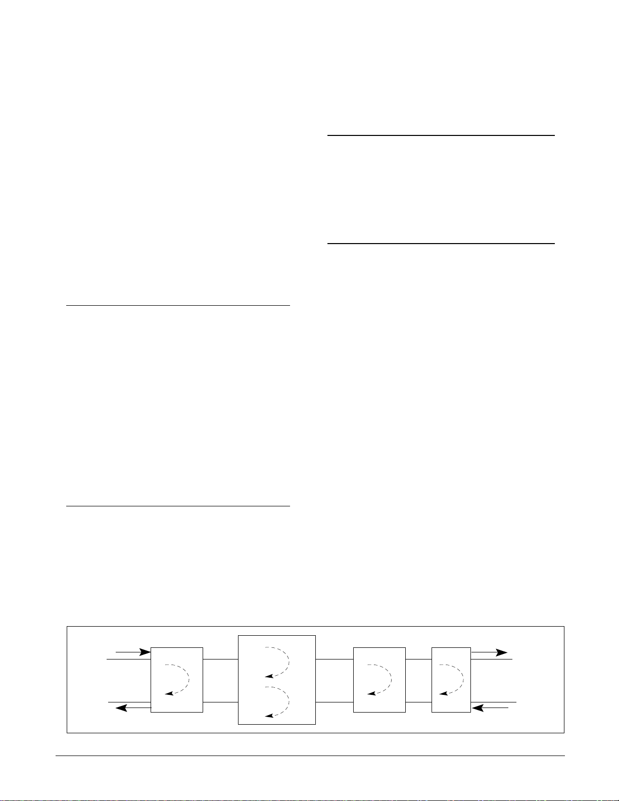
Loop-up State
In the oop-up state, the se ected HDSL e ement
provides continuous oop-up of the DS1 signa .
However, the data f ow is monitored for the in-band
deactivation sequence, the in-band disarming
sequence, and the ESF data ink disarming sequence.
A so, a oop-up timeout va ue causes automatic return
to the armed state. A other contro code sequences
are ignored in the oop-up state.
Transition from loop-up to armed state:
Any HDSL e ement can be commanded to move from
the oop-up state into the armed state by a sing e
in-band 16-bit deactivate contro code sequence. The
same deactivation sequence as shown is used for a
HDSL e ements.
DEACTIVATION
after receiving sequence for >5 seconds
Duration of the deactivation sequence may need to
exceed 18 seconds to a ow detection and oop-down
of up to three HDSL e ements. The deactivation
sequence does not disarm the HDSL e ements. They
can sti respond to activation sequence contro codes.
A HDSL e ements automatica y move from the
oop-up state into the armed state when the se ected
oop-up timeout va ue is reached.
LOOP-UP TIMEOUT
programmab e from HTU-C at
None, 20, 60, or 120 minutes
Transition from loop-up to disarmed state:
A HDSL e ements can be simu taneous y
commanded to move from the oop-up state into the
disarmed state by either the standard 5-bit in-band
disarming sequence used fro NIU Smartjack
oop-down, or by the ESF DATA LINK command, as
previous y described.
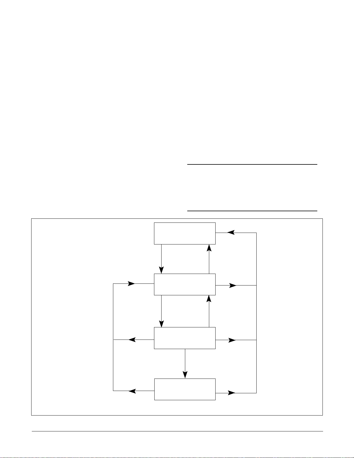
2. ENHANCED LOOPBACKS
HDSL Maintenance Modes
This subsection describes operation of the HDSL
system with regard to detection of in-band and ESF
faci ity data ink oopback codes.