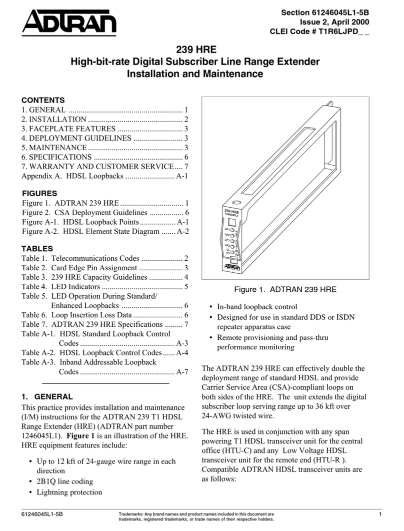
ADTRAN 239 HRE Instruction Manual

HDSL
239 Range Extender
Installation and Maintenance Practice
Document Number: 61247045L1-5A
CLEI: T1IRPAACB_ _
June 2008
®

HDSL 239 Range Extender Installation and Maintenance Practice
ii 61247045L1-5A
Front Matter
Trademarks
Any brand names and product names included in this document are trademarks, registered
trademarks, or trade names of their respective holders.
To the Holder of this Document
The contents of this document are current as of the date of publication. ADTRAN®reserves the
right to change the contents without prior notice.
In no event will ADTRAN be liable for any special, incidental, or consequential damages or
for commercial losses even if ADTRAN has been advised thereof as a result of issue of this
document.
901 Explorer Boulevard
P.O. Box 140000
Huntsville, AL 35814-4000
(256) 963-8000
United States
©2008 ADTRAN, Inc.
All Rights Reserved.
®

61247045L1-5A iii
Revision History
Conventions
The following typographical conventions are used in this document:
This font indicates a cross-reference link.
This font indicates screen menus, fields, and parameters.
THIS FONT indicates keyboard keys (ENTER, ESC, ALT). Keys that are to be pressed simultaneously
are shown with a plus sign (ALT+Xindicates that the ALT key and Xkey should be pressed at the
same time).
This font indicates references to other documentation and is also used for emphasis.
This font indicates on-screen messages and prompts.
This font indicates text to be typed exactly as shown.
This font indicates silk-screen labels or other system label items.
This font is used for strong emphasis.
NOTE
Notes inform the user of additional, but essential, information or
features.
CAUTION
Cautions inform the user of potential damage, malfunction, or
disruption to equipment, software, or environment.
WARNING
Warnings inform the user of potential bodily pain, injury, or death.
Revision Date Description
AJune 2008 Initial release

HDSL 239 Range Extender Installation and Maintenance Practice
iv 61247045L1-5A
Training
ADTRAN offers training courses on our products. These courses include overviews on product
features and functions while covering applications of ADTRAN product lines. ADTRAN
provides a variety of training options, including customized training and courses taught at our
facilities or at customer sites.
For inquiries concerning training, contact ADTRAN:
Training Phone: 800-615-1176, ext. 6996
Training Fax: 256-963-6217

61247045L1-5A v
Contents
General . . . . . . . . . . . . . . . . . . . . . . . . . . . . . . . . . . . . . . . . . . . . . . . . . . . . . . . . . . . . . . . . . . . . . . . . . . . . . . . . . . 1
Description. . . . . . . . . . . . . . . . . . . . . . . . . . . . . . . . . . . . . . . . . . . . . . . . . . . . . . . . . . . . . . . . . . . . . . . . . . . . . 2
Features . . . . . . . . . . . . . . . . . . . . . . . . . . . . . . . . . . . . . . . . . . . . . . . . . . . . . . . . . . . . . . . . . . . . . . . . . . . 2
HDSL Compatibility . . . . . . . . . . . . . . . . . . . . . . . . . . . . . . . . . . . . . . . . . . . . . . . . . . . . . . . . . . . . . . . . . . . 2
Compliance . . . . . . . . . . . . . . . . . . . . . . . . . . . . . . . . . . . . . . . . . . . . . . . . . . . . . . . . . . . . . . . . . . . . . . . . . . . . 3
HDSL Deployment Guidelines . . . . . . . . . . . . . . . . . . . . . . . . . . . . . . . . . . . . . . . . . . . . . . . . . . . . . . . . . . . . . . . 5
Installation . . . . . . . . . . . . . . . . . . . . . . . . . . . . . . . . . . . . . . . . . . . . . . . . . . . . . . . . . . . . . . . . . . . . . . . . . . . . . . . 7
Shipping Contents . . . . . . . . . . . . . . . . . . . . . . . . . . . . . . . . . . . . . . . . . . . . . . . . . . . . . . . . . . . . . . . . . . . . . . . 7
Instructions for Installing the Module . . . . . . . . . . . . . . . . . . . . . . . . . . . . . . . . . . . . . . . . . . . . . . . . . . . . . . . . . 7
Compatible Repeater Housings. . . . . . . . . . . . . . . . . . . . . . . . . . . . . . . . . . . . . . . . . . . . . . . . . . . . . . . . . . . . . 8
Connections. . . . . . . . . . . . . . . . . . . . . . . . . . . . . . . . . . . . . . . . . . . . . . . . . . . . . . . . . . . . . . . . . . . . . . . . . . . 10
Front Panel LEDs . . . . . . . . . . . . . . . . . . . . . . . . . . . . . . . . . . . . . . . . . . . . . . . . . . . . . . . . . . . . . . . . . . . . . . 11
Maintenance . . . . . . . . . . . . . . . . . . . . . . . . . . . . . . . . . . . . . . . . . . . . . . . . . . . . . . . . . . . . . . . . . . . . . . . . . . . . . 11
Specifications. . . . . . . . . . . . . . . . . . . . . . . . . . . . . . . . . . . . . . . . . . . . . . . . . . . . . . . . . . . . . . . . . . . . . . . . . . . . 12
Appendix A
HDSL Loopbacks . . . . . . . . . . . . . . . . . . . . . . . . . . . . . . . . . . . . . . . . . . . . . . . . . . . . . . . . . . . . . . . . A-1
HDSL Maintenance Modes . . . . . . . . . . . . . . . . . . . . . . . . . . . . . . . . . . . . . . . . . . . . . . . . . . . . . . . . . . . . . A-1
HTU-C Loopback . . . . . . . . . . . . . . . . . . . . . . . . . . . . . . . . . . . . . . . . . . . . . . . . . . . . . . . . . . . . . . . . . . A-1
HTU-R Loopback . . . . . . . . . . . . . . . . . . . . . . . . . . . . . . . . . . . . . . . . . . . . . . . . . . . . . . . . . . . . . . . . . . A-1
HRE Loopback . . . . . . . . . . . . . . . . . . . . . . . . . . . . . . . . . . . . . . . . . . . . . . . . . . . . . . . . . . . . . . . . . . . . A-1
Loopback Process Description . . . . . . . . . . . . . . . . . . . . . . . . . . . . . . . . . . . . . . . . . . . . . . . . . . . . . . . . A-2
HDSL Loopback Codes. . . . . . . . . . . . . . . . . . . . . . . . . . . . . . . . . . . . . . . . . . . . . . . . . . . . . . . . . . . . . . A-3
Appendix B
Warranty . . . . . . . . . . . . . . . . . . . . . . . . . . . . . . . . . . . . . . . . . . . . . . . . . . . . . . . . . . . . . . . . . . . . . . . B-1
Warranty and Customer Service . . . . . . . . . . . . . . . . . . . . . . . . . . . . . . . . . . . . . . . . . . . . . . . . . . . . . . . . B-1
ADTRAN Sales . . . . . . . . . . . . . . . . . . . . . . . . . . . . . . . . . . . . . . . . . . . . . . . . . . . . . . . . . . . . . . . . . . . . B-1
ADTRAN Technical Support . . . . . . . . . . . . . . . . . . . . . . . . . . . . . . . . . . . . . . . . . . . . . . . . . . . . . . . . . . B-1
ADTRAN Repair/CAPS . . . . . . . . . . . . . . . . . . . . . . . . . . . . . . . . . . . . . . . . . . . . . . . . . . . . . . . . . . . . . . B-1
Repair and Return Address. . . . . . . . . . . . . . . . . . . . . . . . . . . . . . . . . . . . . . . . . . . . . . . . . . . . . . . . . . . B-1

HDSL 239 Range Extender Installation and Maintenance Practice
vi 61247045L1-5A
Figures
Figure 1. 239 HRE Front Panel . . . . . . . . . . . . . . . . . . . . . . . . . . . . . . . . . . . . . . . . . . . . . . . . . . . . . . . . . . . . 1
Figure 2. HDSL Deployment Guidelines. . . . . . . . . . . . . . . . . . . . . . . . . . . . . . . . . . . . . . . . . . . . . . . . . . . . . . 5
Figure A-1. HDSL Loopback Points . . . . . . . . . . . . . . . . . . . . . . . . . . . . . . . . . . . . . . . . . . . . . . . . . . . . . . . . . .A-1
Figure A-2. HDSL Element State Diagram. . . . . . . . . . . . . . . . . . . . . . . . . . . . . . . . . . . . . . . . . . . . . . . . . . . . .A-2
Tables
Table 1. HDSL Compatibility . . . . . . . . . . . . . . . . . . . . . . . . . . . . . . . . . . . . . . . . . . . . . . . . . . . . . . . . . . . . . . 2
Table 2. 239 HRE Compliance Codes . . . . . . . . . . . . . . . . . . . . . . . . . . . . . . . . . . . . . . . . . . . . . . . . . . . . . . 3
Table 3. HDSL Loss Values . . . . . . . . . . . . . . . . . . . . . . . . . . . . . . . . . . . . . . . . . . . . . . . . . . . . . . . . . . . . . . 6
Table 4. Loop Insertion Loss Data . . . . . . . . . . . . . . . . . . . . . . . . . . . . . . . . . . . . . . . . . . . . . . . . . . . . . . . . . 6
Table 5. Compatible Repeater Housings . . . . . . . . . . . . . . . . . . . . . . . . . . . . . . . . . . . . . . . . . . . . . . . . . . . . 8
Table 6. 239 HRE Edge Connectors Pin. . . . . . . . . . . . . . . . . . . . . . . . . . . . . . . . . . . . . . . . . . . . . . . . . . . . 10
Table 7. Front Panel LEDs . . . . . . . . . . . . . . . . . . . . . . . . . . . . . . . . . . . . . . . . . . . . . . . . . . . . . . . . . . . . . . 11
Table 8. 239 HRE Specifications. . . . . . . . . . . . . . . . . . . . . . . . . . . . . . . . . . . . . . . . . . . . . . . . . . . . . . . . . . 12
Table A-1. HDSL Loopback Control Codes . . . . . . . . . . . . . . . . . . . . . . . . . . . . . . . . . . . . . . . . . . . . . . . . . . .A-3

HDSL 239 Range Extender Installation and Maintenance Practice
261247045L1-5A
Description
The ADTRAN 239 HRE can effectively double the deployment range of standard HDSL and
provide Carrier Service Area (CSA) compliant loops on both sides of the HRE. The unit extends
the digital subscriber loop serving range up to 24 kft over 24-AWG twisted wire.
Features
The 239 HRE includes the following basic features:
• Up to 12 kft of 24-gauge wire range in each direction
• 2B1Q line coding
• Lightning protection
• In-band loopback control
• Designed for use in standard DDS or ISDN repeater apparatus case
• Remote provisioning and pass-thru performance monitoring
HDSL Compatibility
The HRE is used in conjunction with any span powering T1 HDSL transceiver unit for the
central office (HTU-C) and any HDSL transceiver unit for the remote end (HTU-R).
Table 1 lists compatible ADTRAN HDSL transceiver units.
Table 1. HDSL Compatibility
Part Number Description
124600xLx 6th Gen HTU-C
1247002Lx 7th Gen Litespan HTU-C
1247001Lx 7th Gen 220 HTU-C
1247003Lx 7th Gen DDM+ HTU-C
1247004Lx 7th Gen 3192 HTU-C
1247024L1 7th Gen T200 HTU-R, LP/60 mA
1247026Lx 7th Gen T200 HTU-R, SP/60 mA

General
61247045L1-5A 3
Compliance
The 239 HRE is NRTL Listed to the applicable UL standards for continuous use in –40°C to +50°C
environmental conditions. Care should be exercised when handling equipment when tempera-
tures at these extremes exist, as surfaces could be very cold or hot.
The 239 HRE meets or exceeds all the applicable requirements of NEBS, Telcordia GR-63-CORE
and GR-1089-CORE and is evaluated to ensure proper Operational Performance is
maintained if Environmental Conditions ranging from –40°C to +71°C are encountered.
The 239 HRE is intended for deployment in 239 repeater/apparatus cases, EECs, and
locations where the NEC applies (for example, Customer Premises). Install the 239 HRE in the
appropriate chassis, which is intended to be installed only in Restricted Access Locations by
qualified personnel.
The compliance codes for the 239 HRE are listed below in Table 2.
This device complies with Part 15 of the FCC rules. Operation is subject to the following two
conditions:
1. This device may not cause harmful interference
2. This device must accept any interference received, including interference that may cause
undesired operation.
Changes or modifications not expressly approved by ADTRAN could void the user’s authority
to operate this equipment.
WARNING
Voltages up to –200 VDC with respect to ground may be present on
the HDSL telecommunications conductors. Voltages up to 200
VDC may be present between individual HDSL telecommunications
conductors.
CAUTION
Per GR-1089-CORE the HDSL System is designed and intended for
installation as part of a Common Bonding Network (CBN). The
HDSL System is not designed nor intended for installation as part
of an Isolated Bonding Network (IBN).
Table 2. 239 HRE Compliance Codes
Configuration Code Input Output
Power Code (PC) C C
Telecommunication Code (TC) X X
Installation Code A –

HDSL 239 Range Extender Installation and Maintenance Practice
461247045L1-5A
CAUTION
The 239 HRE does not have a local Power Connection. As such
there are no special requirements regarding treatment of the
battery return leads as described in GR-1089-CORE.
NOTE
The HDSL ports are classified as Type 3 and 5, as defined in
Appendix B of GR-1089-CORE Issue 4, and meet the lightning and
power fault criteria of GR-1089-CORE issue 4 with primary
protectors that meet any of the voltage limits of GR-974-CORE or
GR-1361-CORE (for example, carbon blocks, gas tubes, solid
state).
NOTE
Current limiting protectors are not required.

HDSL Deployment Guidelines
61247045L1-5A 5
HDSL DEPLOYMENT GUIDELINES
The ADTRAN HDSL system is designed to provide DS1 based services over loops designed to
comply with carrier service area (CSA) guidelines. CSA deployment guidelines are given below.
• All loops are non-loaded only.
• For loops with 26-AWG cable, the maximum loop length including bridged tap lengths is 9 kft.
• For loops with 24-AWG cable, the maximum loop length including bridged tap lengths is 12 kft.
• Any single bridged tap is limited to 2 kft.
• Total bridged tap length is limited to 2.5 kft.
• The total length of multi-gauge cable containing 26-AWG cable must not exceed the
following:
–12–{(3*L
26)/(9 – LBTAP)} (in kft)
Where:
-L
26= Total length of 26-AWG cable excluding bridged taps (in kft)
-L
BTAP= Total length of all bridged taps (in kft)
This deployment criteria is summarized in the chart shown in Figure 2.
Loop loss per kft for other wire is summarized in Table 3.
Figure 2. HDSL Deployment Guidelines
0
12
11
10
9
8
7
6
5
4
3
2
1
0
1234
WORKING LENGTH OF 26 GAUGE CABLE (KFT)
WORKING LENGTH OF 24 GAUGE (OR COARSER) CABLE (KFT)
56789
2.5 2.0 1.5 1.0 0.5 0.0
TOTAL
BRIDGED
TAP
LENGTH
(KFT)
VALID HDSL CABLE LENGTHS
INVALID HDSL CABLE LENGTHS

HDSL 239 Range Extender Installation and Maintenance Practice
661247045L1-5A
Recommended maximum local loop loss information for PIC cable at 70°F, 135 Ωresistive
termination is provided in Table 4.
An approximation for the maximum amount of wideband noise on an HDSL local loop as
measured by a 50 kb filter is ≤31 dBrn.
An approximation for the maximum level of impulse noise as measured using a 50 kb filter on
an HDSL loop is ≤50 dBrn.
NOTE
These approximations are to be used as guidelines only and may
vary slightly on different loops. Adhering to the guidelines should
produce performance in excess of 10-7 BER.
Table 3. HDSL Loss Values
(200 kHz cable loss in dB/kft at 135 Ω)
Cable Gauge Cable Type Temperature
68° 90° 120°
26 PIC 3.902 4.051 4.253
26 Pulp 4.030 4.179 4.381
24 PIC 2.863 2.957 3.083
24 Pulp 3.159 3.257 3.391
22 PIC 2.198 2.255 2.333
22 Pulp 2.483 2.45 2.629
19 PIC 1.551 1.587 1.634
19 Pulp 1.817 1.856 1.909
Table 4. Loop Insertion Loss Data
Frequency (Hz) Maximum Loss (dB)
3000 12.00
10000 15.00
50000 25.50
100000 30.00
150000 32.75
196000 35.00
200000 32.25
250000 37.50
325000 42.00

Installation
61247045L1-5A 7
INSTALLATION
CAUTION
Electrostatic Discharge (ESD) can damage electronic modules.
When handling modules, wear an antistatic discharge wrist strap
to prevent damage to electronic components. Place modules in
antistatic packing material when transporting or storing. When
working on modules, always place them on an approved antistatic
mat that is electrically grounded.
After unpacking the 239 HRE, inspect it for damage. If damage has occurred, file a claim with
the carrier then contact ADTRAN Customer Service. Refer to “Appendix B, Warranty” for
further information. If possible, keep the original shipping container for returning the 239
HRE for repair or for verification of shipping damage.
Shipping Contents
The contents include the following items:
• 239 Range Extender
•HDSL 239 Range Extender Job Aid (P/N 61247045L1-22)
•HDSL 239 Range Extender Compliance Notice (P/N 61247045L1-17)
Instructions for Installing the Module
The 239 HRE can be installed in any enviromentally controlled 239 and 819 repeater housing.
Refer to the appropriate repeater housing documentation for the procedure to access the
individual repeater slots.
Once the repeater housing is accessable, perform the following steps to install the 239 HRE:
1. Hold the 239 HRE by the front panel
2. Align the pins on each repeater with the connector inside the repeater housing.
3. Insert the module into the required repeater location. Simultaneous thumb pressure at
the top (above the part number) and at the bottom (below the ADTRAN logo) of the module
will ensure that the module is firmly positioned within the repeater housing.
When the 239 HRE first powers up it runs the power up self-tests. Once the power up self-test is
complete, the status LEDs reflect the true state of the hardware. Follow housing documentation
to close and seal the repeater housing.
C A U T I O N !
SUBJECT TO ELECTROSTATIC DAMAGE
OR DECREASE IN RELIABILITY.
HANDLING PRECAUTIONS REQUIRED.

HDSL 239 Range Extender Installation and Maintenance Practice
861247045L1-5A
Compatible Repeater Housings
The 239 HRE can be installed in all standard 239 and 819 Repeater housings. Table 5 lists examples of available housings.
Table 5. Compatible Repeater Housings
Description Part Number CLEI Stub Slots Material Mechanics
HRE Capacity
Above Ground Below Ground
ADTRAN
239/439
1150027L1
1150027L2
DDMOABA1MA
DDMOBBA1MA
Air-core
Gel-filled 4Stainless
Steel 239/439 4 4
ADTRAN
239/439
1152010L4
1152010L3
DDMOAAE1RA
DDMOBAE1RA
Air-core
Gel-filled 2Valox
Plastic 239/439 2 2
ADTRAN
4-slot
Universal
1150057L1
1150057L2
DDMODA01RA
DDMOCA01RA
Air-core
Gel-filled 4Stainless
Steel
239/439/
819 4 (1) 4
ADTRAN
8-Slot
Universal
1150058L1
1150058L2
DDMOEE01RA
DDMOFE01RA
Air-core
Gel-filled 8Stainless
Steel
239/439/
819
6(1)
8
AT&T 819 N/A Air-core 25 Polymer 239/819A
12 16 (2)
AT&T 820 N/A Air-core 8Stainless
Steel 239 8 (1) 8
1, 4, 7, 8,
11, 14,15,
17, 19, 20,
23, 25 1, 3, 5, 7, 8, 10, 12,
14, 15, 16, 18, 19,
20, 22, 24, 25

Installation
61247045L1-5A 9
AT&T 809 N/A Air-core 12 Polymer 239
6
N/A
AT&T 841C N/A Air-core 100 Stainless
Steel 239 42 N/A
SPC 6-slot N/A Air-core
Gel-filled 6Stainless
Steel
239/439
(no 819A)
5 (1)
6
SPC 8-slot N/A Air-core
Gel-filled 8Stainless
Steel
239/439
(no 819A)
7 (1)
8
1. Vertical stub down only
2. Up to 16 units can be loaded inside the 819 housing for all below ground mounting orientations. If the 819 housing is mounted specifically in the
vertical, stub down direction, 18 units can be loaded in slots 1, 3, 5, 7, 8, 10, 12, 13, 14, 15, 17, 18, 19, 20, 21, 22, 24, and 25.
Table 5. Compatible Repeater Housings (Continued)
Description Part Number CLEI Stub Slots Material Mechanics
HRE Capacity
Above Ground Below Ground
1, 3, 5, 7, 9, 11

HDSL 239 Range Extender Installation and Maintenance Practice
10 61247045L1-5A
Connections
All connections of the 239 HRE are made through card edge connectors. Table 6 lists the 239
HRE card edge connector pin.
CAUTION
The 239 HRE dissipates a maximum of 4.5 watts.
NOTE
Ensure that the chassis ground is securely connected to the
apparatus case. Ground pin designations are defined in Table 6.
Table 6. 239 HRE Edge Connectors Pin
Pin Designation Description
1GND Ground
2NC No Connect
3T1 Customer Loop 1 Tip
4R1 Customer Loop 1 Ring
5T1 Network Loop 1 Tip
6R1 Network Loop 1 Ring
7NC No Connect
8 T Network Loop 2 Tip
9 R Network Loop 2 Ring
10 GND Ground
11 TCustomer Loop 2 Tip
12 RCustomer Loop 2 Ring

Maintenance
61247045L1-5A 11
Front Panel LEDs
The 239 HRE provides front panel LEDs to display status information. Table 7 shows the 239
HRE LEDs and status descriptions.
MAINTENANCE
The 239 HRE does not require routine maintenance for normal operation. Do not attempt to
repair the 239 HRE in the field. Repair services are obtained by returning the defective unit to
ADTRAN. Refer to “Appendix B, Warranty” for further information.
Table 7. Front Panel LEDs
Label Status Description
NET LP1/LP2 {
z
z
z
5
Off
Green
Yellow
Red
Flashing
Loss of power to the HRE or no sync with the next upstream device
(HTU-C/HRE#1)
Sync with good signal quality (> 7)
Sync with marginal signal quality (1 to 7)
Sync with poor signal quality (0)
Fast yellow flash for NET LP1 when span powering present, but no
synchronization. If the pulse attenuation (LOSS on Current Sys-
tem Status Screen) is above 30 dB or a CRC error was received at
the NET LP1/LP2 receiver, the NET LP1/LP2 LED flashes green, yel-
low, or red, as determined by the signal quality. If the pulse atten-
uation is above 30 dB and a CRC error was received at the same
time, the LED flashes twice as fast.
CUST LP1/LP2 {
z
z
z
5
Off
Green
Yellow
Red
Flashing
No sync with the next downstream device (HTU-R/HRE#2) on
CUST LP1/LP2
Sync with good signal quality (> 7)
Sync with marginal signal quality (1 to 7)
Sync with poor signal quality (0)
If the pulse attenuation (LOSS on Current System Status Screen)
is above 30 dB or a CRC error was received at the CUST LP1 / LP2
receiver, the CUST LP1/LP2 LED flashes green, yellow, or red, as
determined by the signal quality. If the pulse attenuation is above
30 dB and a CRC error was received at the same time, the LED
flashes twice as fast.
LL/RL z
z
Green
Yellow
Unit is looped toward the HTU-R
Unit is looped toward the HTU-C

HDSL 239 Range Extender Installation and Maintenance Practice
12 61247045L1-5A
SPECIFICATIONS
Table 8 details the specifications for the 239 HRE.
Table 8. 239 HRE Specifications
Specification Description
Loop Interface
Modulation Type:
Mode:
Number of Pairs:
Bit Rate:
Baud Rate:
Service Range:
Loop Loss:
Bridged Taps:
Performance:
Return Loss:
HDSL Tx Signal Level:
Input Impedance:
DS1 Channelization:
2B1Q
Full duplex; echo cancelling
Two
784 kbps per pair
392K baud per pair
Defined by CSA guidelines
35 dB maximum at 196 kHz
Single taps < 2kft; Total Taps < 2.5 kft
Compliant with Bellcore TA-NWT-001210
20 dB (40 kHz to 200 kHZ)
13.5 dBm
135 Ω
Channels 1-12 on Loop 1; Channels 13-24 on
Loop 2
Power
Input Power: Span-powered by HTU-C, 3.5 watts (maximum)
Environmental
Operating Temperature:
Storage Temperature:
Relative Humidity:
–40°C to 71°C
–40°C to 85°C
95 percent maximum @ 50°C, noncondensing
Tests
Diagnostics: Loopback initiated with HDSL in-band codes or
from HTU-C or HTU-R craft interface.
Self-test initiated from the HTU-C or HTU-R.
Physical
Dimensions:
Weight:
Height: 0.719 inches
Width: 2.625 inches
Depth: 6.5 inches
< 1 pound
Part Number
HDSL 239 Range Extender: 1247045L1

61247045L1-5A A-1
Appendix A
HDSL Loopbacks
HDSL MAINTENANCE MODES
This Appendix describes operation of the HDSL system with regard to detection of in-band and
ESF facility data link loopback codes. The operation of the loopback commands in the
ADTRAN HDSL system is compliant with the recommendation to ANSI recorded in T1E1.4/92.
The HDSL network loopback points described below are shown in Figure A-1.
HTU-C Loopback
A regenerative loopback of the DSX-1 signal toward the network.
HTU-R Loopback
A regenerative loopback of the DS1 signal toward the network. This loopback is in addition to
a separate Smartjack loopback. Separate activation sequences are provided for the HTU-R and
the Smartjack loopback initiation.
HRE Loopback
A regenerative loopback of the HDSL signal toward the network.
Upon deactivation of a loopback, the HDSL system synchronizes automatically. Note that the
synchronization process of the HDSL system upon deactivation of the HRE loopback could
take up to 15 seconds, ensuring all system elements are synchronized.
Figure A-1. HDSL Loopback Points
HTU-C
DSX-1
Interface
HRE
HDSL
Loops
HDSL
Loops
HTU-R NIU
DS1
Interface

HDSL 239 Range Extender Installation and Maintenance Practice
A-2 61247045L1-5A
Loopback Process Description
In general, the loopback process for the HDSL system elements is modeled on the corresponding
DS1 system process. Specifically, the HTU-C loopback is similar to an Intelligent Office
Repeater loopback and the HTU-R loopbacks are similar to an inline T1 Repeater loopback.
Each HDSL system element is independently described by the state diagram shown in
Figure A-2. The four states are disarmed, loop-up, armed, and loop-up/time-out disable.
Figure A-2. HDSL Element State Diagram
State transitions result from in-band and ESF Data Link sequences as well as timeout operations.
The sequences and timeout values are as follows:
• Arming Sequence (in-band and ESF)
• Activation Sequence
• Deactivation Sequence
• Disarming Sequence (in-band and ESF)
• Loop-up Timeout
• Arming Timeout
DEACTIVATION
ACTIVATION LOOP-UP
TIMEOUT
DISARM
DISARMED
STATE
ARMED
STATE
LOOP-UP/TIMEOUT
STATE
LOOP-UP/NO TIMEOUT
STATE
LOOP-UP
TIMEOUT
DISABLE*
* The Loop-up Timeout Disable function is currently not supported.
ARMING
TIMEOUT
This manual suits for next models
1
Table of contents
Other ADTRAN Extender manuals
Popular Extender manuals by other brands

StarTech.com
StarTech.com USBthere USB221EXT Specifications

Hall Research Technologies
Hall Research Technologies U3CAT6 Series user manual

SmoothTalker
SmoothTalker Mobile X650 4G LTE user manual

SMART-AVI
SMART-AVI SFX-2P quick start guide

Triplett
Triplett POC-300M user manual

Cables to Go
Cables to Go TruLink 39959 user manual