88
88
8 - FORM NO. 56041549 - Reel Cleaner™
KNOW YOUR MACHINE DESCRIPTIONSKNOW YOUR MACHINE DESCRIPTIONS
KNOW YOUR MACHINE DESCRIPTIONSKNOW YOUR MACHINE DESCRIPTIONS
KNOW YOUR MACHINE DESCRIPTIONS
Operator Handle (1)Operator Handle (1)
Operator Handle (1)Operator Handle (1)
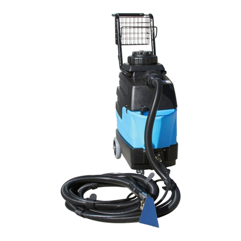
Operator Handle (1) – Operator holds onto this handle to move the machine from one location to another.
Solution Tank Lid (2)Solution Tank Lid (2)
Solution Tank Lid (2)Solution Tank Lid (2)
Solution Tank Lid (2) – Fill Solution Tank Here. DO NOT add chemicals to Solution Tank, only clean, warm water.
Accessories (3)Accessories (3)
Accessories (3)Accessories (3)
Accessories (3) – Various accessories can be stored on the machine.
Recovery Tank Lid (4)Recovery Tank Lid (4)
Recovery Tank Lid (4)Recovery Tank Lid (4)
Recovery Tank Lid (4)–The Recovery Tank can be flushed out by running clean warm water into this opening with the Recovery Tank Drain Hose
open. The Vacuum Float Shut-OFF can also be accessed through this opening for maintenance.
Recovery Hose (5)Recovery Hose (5)
Recovery Hose (5)Recovery Hose (5)
Recovery Hose (5) – Waste water is picked up through this hose.
Spray Hose (6)Spray Hose (6)
Spray Hose (6)Spray Hose (6)
Spray Hose (6) – 300PSI hose for using spray attachments such as the Spray Gun (7)(7)
(7)(7)
(7). Connects to the Quick Disconnect (9)(9)
(9)(9)
(9).
Spray Gun (7)Spray Gun (7)
Spray Gun (7)Spray Gun (7)
Spray Gun (7) – High / Low pressure spraying attachment, connects to Spray Hose (6)(6)
(6)(6)
(6). Pull OUT on nozzle body (7A)(7A)
(7A)(7A)
(7A) for LOW pressure. Push
IN on nozzle body (7A)(7A)
(7A)(7A)
(7A) for high pressure. Turn nozzle body (7A)(7A)
(7A)(7A)
(7A) counter-clockwise for narrow spray pattern. Turn nozzle body (7A)(7A)
(7A)(7A)
(7A) clockwise
for wide spray pattern.
Recovery Tank Drain Hose (8)Recovery Tank Drain Hose (8)
Recovery Tank Drain Hose (8)Recovery Tank Drain Hose (8)
Recovery Tank Drain Hose (8)-Used to emptythe recovery tank. NOTE:NOTE:
NOTE:NOTE:
NOTE:Holdthe end of the hose above the water level in the tank to avoid sudden,
uncontrolled flow of waste water when removing plug.
Quick Disconnect (9)Quick Disconnect (9)
Quick Disconnect (9)Quick Disconnect (9)
Quick Disconnect (9) – Point of attachment for the Spray Hose (6)(6)
(6)(6)
(6).
Front Castor (10)Front Castor (10)
Front Castor (10)Front Castor (10)
Front Castor (10) – Pivoting castors for steering unit while moving from one location to another. Each castor also has a parking brake lever to
prevent unit from rolling.
Blow-Dry Connector (11)Blow-Dry Connector (11)
Blow-Dry Connector (11)Blow-Dry Connector (11)
Blow-Dry Connector (11) –Connect Hose (14)(14)
(14)(14)
(14) to this connector to use the vacuum motor exhaust for blow drying wet floors. Turn ON vac motor
(B)(B)
(B)(B)
(B) after connecting hose.
Solution Filter (12)Solution Filter (12)
Solution Filter (12)Solution Filter (12)
Solution Filter (12) – Inline solution filter prevents contaminants from entering the pump.
Rear Wheel (13)Rear Wheel (13)
Rear Wheel (13)Rear Wheel (13)
Rear Wheel (13) – Rear Wheel of unit.
Blow-Dry Hose (14)Blow-Dry Hose (14)
Blow-Dry Hose (14)Blow-Dry Hose (14)
Blow-Dry Hose (14) – Connect this hose to Connector (11)(11)
(11)(11)
(11) to use the vacuum motor exhaust for blow drying wet floors. Turn ON vac motor (B)(B)
(B)(B)
(B)
after connecting hose.
Recovery Hose Inlet (15)Recovery Hose Inlet (15)
Recovery Hose Inlet (15)Recovery Hose Inlet (15)
Recovery Hose Inlet (15) – Point of attachment for the Recovery Hose (5)(5)
(5)(5)
(5). Waste water enters the Recovery Tank through this opening.
Solution Fill Hose (16)Solution Fill Hose (16)
Solution Fill Hose (16)Solution Fill Hose (16)
Solution Fill Hose (16) – This hose is tethered to the Solution Tank Lid for the purpose of filling the solution tank in the event you do not already
haveahoseatthefaucetyouareusing. Itisastandardgardenhosefemalefitting. Anadaptorisincludedwiththishoseforthepurposeofconnecting
to inside or outside thread faucet aerators.
ChemicalFeed Lines(17)ChemicalFeed Lines(17)
ChemicalFeed Lines(17)ChemicalFeed Lines(17)
ChemicalFeed Lines(17)–Thesetubesareusedtoconnectcleaningchemicalcontainerstothemachine. MeteringTipsforchangingthechemical
to water ratio are installed here.
Switch Plate (18)Switch Plate (18)
Switch Plate (18)Switch Plate (18)
Switch Plate (18) – The machine’s electronic controls are found here.
Power Cord (19)Power Cord (19)
Power Cord (19)Power Cord (19)
Power Cord (19) – This is the machine’s main power cord, it connects at the right lower rear corner of the machine. It can be wrapped around
the Operator Handle (1)(1)
(1)
(1)
(1) when not in use.
Chemical Container Holders (20)Chemical Container Holders (20)
Chemical Container Holders (20)Chemical Container Holders (20)
Chemical Container Holders (20) – Bottle Holders for standard 1 gallon plastic chemical jugs.
Operator Handle Adjustment Knobs (21)Operator Handle Adjustment Knobs (21)
Operator Handle Adjustment Knobs (21)Operator Handle Adjustment Knobs (21)
Operator Handle Adjustment Knobs (21) – The Operator Handle (1)(1)
(1)(1)
(1) can be adjusted up or down by loosening these knobs, moving the handle
into the desired position and then re-tightening.
SWITCH PLASWITCH PLA
SWITCH PLASWITCH PLA
SWITCH PLATE DESCRIPTIONSTE DESCRIPTIONS
TE DESCRIPTIONSTE DESCRIPTIONS
TE DESCRIPTIONS
Solution Switch (A)Solution Switch (A)
Solution Switch (A)Solution Switch (A)
Solution Switch (A) – This switch turns ON the solution pump.
Vacuum Switch (B)Vacuum Switch (B)
Vacuum Switch (B)Vacuum Switch (B)
Vacuum Switch (B) – This switch turns ON the vacuum motor.
Chemical Valve (C)Chemical Valve (C)
Chemical Valve (C)Chemical Valve (C)
Chemical Valve (C) – This valve switches between chemical containers. When the valve is positioned straight up, it is closed. The valve must
be lined up with the ON symbol to draw chemical (see Know Your Machine illustration).
OPERAOPERA
OPERAOPERA
OPERATIONTION
TIONTION
TION
11
11
1 FilltheReel Cleanerwith warmwater (2)(2)
(2)(2)
(2)andinstall containersofchemical (20)(20)
(20)(20)
(20). Ensurethepropermeteringtipsare insertedintheChemical
Feed Lines (17)(17)
(17)(17)
(17).
ColorColor
ColorColor
Color SizeSize
SizeSize
Size Flow Rate (chemical / water)Flow Rate (chemical / water)
Flow Rate (chemical / water)Flow Rate (chemical / water)
Flow Rate (chemical / water)
Red Purple .007 ½ oz / gallon
Light Purple .009 1 oz / gallon
Purple .014 2 oz / gallon
Yellow .020 4 oz / gallon
22
22
2 Push the Reel Cleaner to the area to be cleaned, apply brake (10)(10)
(10)(10)
(10) and plug in the machine.
33
33
3 Prepareareaforcleaningbyemptyingwastereceptacles,clearingdebris,removingpaperproducts,blowingoutventsandsweepingfloors.
44
44
4 Unreel spray hose (6)(6)
(6)(6)
(6), connect to front of machine (9)(9)
(9)(9)
(9), turn on pump switch (A)(A)
(A)(A)
(A) and turn chemical selector (C)(C)
(C)(C)
(C) toward the desired chemical.
55
55
5 Bring hose to the farthest area from the door to be cleaned. With spray gun (7)(7)
(7)(7)
(7) in low-pressure setting, apply chemical from bottom up
to walls and fixtures. Working out of the area, spray floor as finishing.
66
66
6 Allow proper chemical dwell time, according to manufacturer’s directions.
77
77
7 Agitate heavily soiled areas with scrub brush.
88
88
8 Set spray to high pressure and turn chemical selector (C)(C)
(C)(C)
(C) OFF for rinsing area from top to bottom.
99
99
9 Unreel vacuum hose (5)(5)
(5)(5)
(5), attach wand and floor squeegee (3)(3)
(3)(3)
(3), and turn on vacuum switch (B)(B)
(B)(B)
(B).
1010
1010
10 Working way into area, vacuum liquid off the floor.
1111
1111
11 Blow dry (11 & 14)(11 & 14)
(11 & 14)(11 & 14)
(11 & 14) fixtures and squeegee mirrors, if applicable.
1212
1212
12 Drain machine (8)(8)
(8)(8)
(8) into slop sink or commode.
