ADVANCE Easy Moving VACU MATIC FREE Quick setup guide

12
ASSEMBLY, USE AND
MAINTENANCE MANUAL
Fuel extraction system
VACU MATIC FREE


3
• Type: fuel extraction system
• Model: Vacu Matic Free
• Revision 1.0.5
FUEL
EXTRACTION SYSTEM
INSTRUCTION MANUAL
18/07/22 Rev:1.0.5
1 INTRODUCTION 4
1.1 Use of this manual 4
2 WARNINGS 4
3 TECHNICAL DATA, EXPLODED VIEW DRAWINGS AND DIMENSIONS 5
3.1 Identification plate 6
3.2 Safety symbols 6
4 PACKAGING CONTENT 7
5 PROPER USE OF THE PRODUCT 7
5.1 Caratteristiche del magazzino di stoccaggio 8
6 INSTALLATION 8
6.1 Instruction for the installation of systems 8
6.2 Positioning 9
6.3 Connection to the piping network 10
6.4 Electrical connection 11
7 START UP 12
7.1 Switching on and use 12
8 MAINTENANCE AND END-OF-LIFE 13
8.1 Spare parts 13
8.2 End-of-life 13
9 SAFETY REQUIREMENTS FOR FUEL STORAGE TANKS 14
10 WARRANTY 15
11 CERTIFICATION 16
INDEX

Suction case with motorized nozzle
4
18/07/22 Rev:1.0.5
1 INTRODUCTION
Dear customer,
the manufacturer would firstly like to thank you for the choice you made in buying an product, whose
technical features will certainly meet Your needs.
Our products have been designed and manufactured in total compliance with the current regulations, by
choosing the best materials to obtain durability and ease of use of the product.
We ask you, therefore, to read this manual carefully and completely, following strictly the instructions
contained herein.
1.1 Use of this manual
The instruction manual is a document drawn up by the manufacturer and is part of the product: it
integrates the specific rules of application and general rules for people, animals and objects safety. In the
event that the product is resold, handed over, rented or sold to others, it must always be accompanied
by this manual; therefore, it is recommended to use and keep it with care for the entire operative life of
the product.
The main objective of this manual is to make known the proper and safe way to use the equipment.
No part of this manual may be reproduced, copied, or shared in any way, without the written permission
of the manufacturer.
The manufacturer reserves the right to make improvements or modifications to this manual
and to the equipment at any time, without obligation to advise third parties.
2 WARNINGS
• Do not use the machine for any improper use.
• Do not let children near the machine.
• This unit must not be used by people (including children) with reduced physical, sensory or mental
capabilities, or with lack of experience and knowledge, unless they are supervised or instructed in the
use of the unit by a person responsible for their safety.
• Use only original spare parts.
• Do not put parts of the body into contact with the machine before having removed the electrical power.
• Disconnect the power supply when a long period of inactivity is expected.
The manufacturer declines any liability or guarantee, if the buyer or anyone
makes changes or even minor modifications to the purchased product.

5
English
18/07/22 Rev:1.0.5
3 TECHNICAL DATA, EXPLODED VIEW DRAWNGS AND DIMENSIONS
Article
AP3400.00.09
IP ProtecƟon degree IP 40
OperaƟng temperature min/max
°C 0 ÷ 40
Degree of humidity min/max % 30 ÷ 95
Power supply V ac 230
Frequency Hz 50
Motor power W 15
Max absorpƟon A 0,14
Fuse 5x20 T2A
InsulaƟon class 1
RevoluƟons per minute rpm 12
Rated torque Nm 5
Weight
Kg 3,1
Measurement A mm 185
Measurement B mm 108
Measurement C mm 235
Measurement D mm 226
Measurement E mm 261
Measurement F mm 125
Measurement H mm 245
Measurement L mm 80
Measurement R Ømm 6
Measurement S Ømm 50 M
Gearmotor
Frame
Flow regulator
Electronic board
Crankcase
Rod-crank
mechanism
6
5
1
3
2
4
A
B
C
D
E
S
F
H
L
R
F

Suction case with motorized nozzle
6
18/07/22 Rev:1.0.5
....................................
.........................................................................
Model:
P/N: S/N:
Type of equipment Manufacturer identification
CE Mark of
conformity
Technical data of the equipment
Serial number
Item number
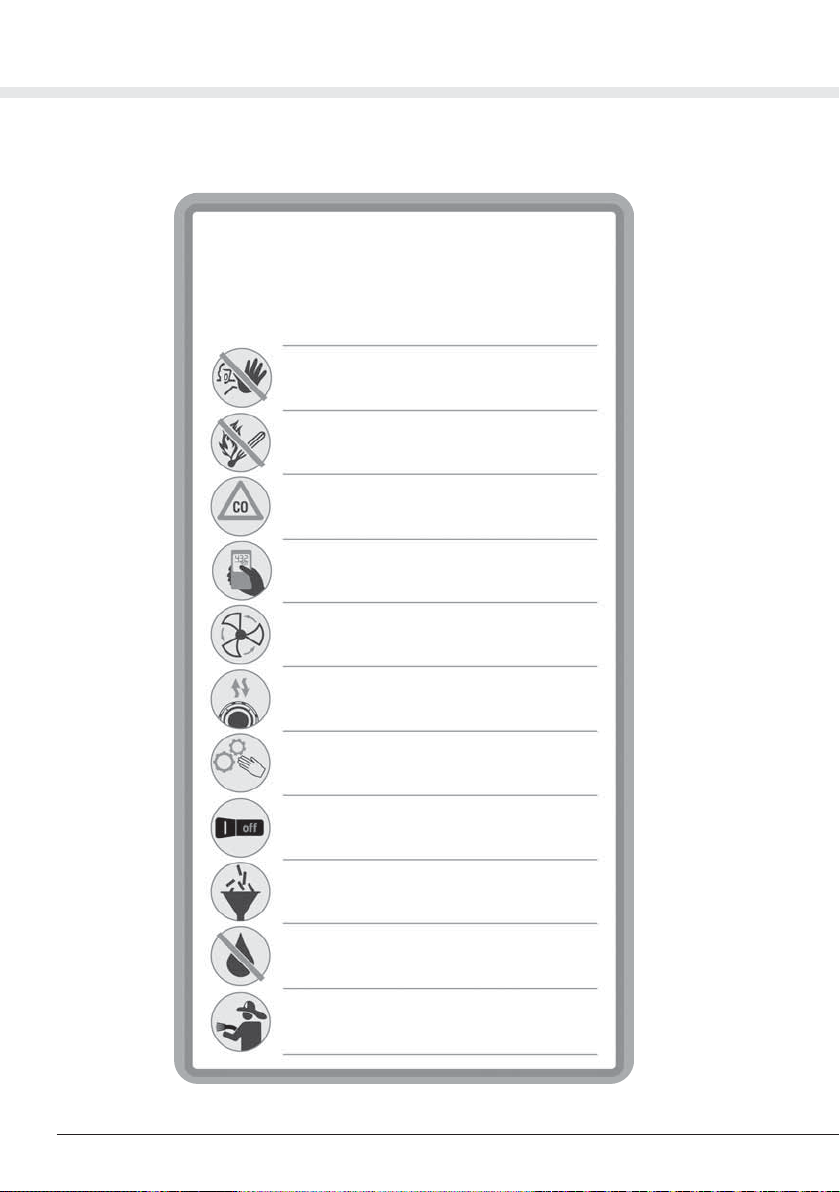
3.1 Identification plate
Do not remove or damage the identification plate.
It is recommended to pay full attention to pictograms and warnings of danger and prohibition in the
present different parts of the equipment: if not respected, hazardous situations may occur.
DANGER OF VOLTAGE OR ELECTRICAL CURRENT
Danger of serious personal injuries.
During maintenance operations, always disconnect the power supply and make sure
that it cannot be restored.
DANGER OF CUTTING
Danger of serious personal injuries.
During maintenance operations, always disconnect the power supply and make sure
that it cannot be restored.
DANGER OF AUTOMATIC STARTING
Danger of serious personal injuries.
During maintenance operations, always disconnect the power supply and make sure
that it cannot be restored.
DANGER FOR THE HAND WHEN THE SCREW CONVEYOR IS IN OPERATION
Danger of serious personal injuries.
During maintenance operations, always disconnect the power supply and make sure
that it cannot be restored.
3.2 Safety symbols

7
English
18/07/22 Rev:1.0.5
Check that the product corresponds to the one ordered and that no transportation damage is
evident.
Should this not be the case, please contact immediately the seller.
5 PROPER USE OF THE PRODUCT
The suction caser has been designed to be installed for the pneumatic transport of pellets or other
biomass fuels with a medium-fine size;
it has the task of extracting the fuel from the bottom of any hopper tank.
This product is suitable for the extraction of biomass fuel such as pellets, olive pomace,
wood chips, crushed shells of dried fruit, corn, but it cannot work with fuels having a very
fine size, or having excessive dimensions and, in any case, having lengths over 40 mm or
diameter greater than 15 mm.
It is recommended to use only ENplus A1 certified pellet.
To provide the job for which it was designed, the suction case must be connected to a control
panelcalledthatcontrolstheoperationoftheentirepneumatictransportsystemortoanintegrated
central vacuum unit called.
Once installed and connected, the suction case extracts the fuel until the tank is completely
empty; by the movement of the rod-crank mechanism positioned in front of the suction inlet, a
possible blockage or clogging of the inlet itself because of slag or irregular dimensions fuel is
avoided.
4 PACKAGING CONTENT
After opening the packaging, verify that the material contained in it conforms to the following list:
1) Extraction system
2) Assembly, use and maintenance manual
3) Flow regulator
4) gum sleeves + 2 hose clamps
5) Warranty form
2
3
4
Manuale Tecnico
1
5

Suction case with motorized nozzle
8
18/07/22 Rev:1.0.5
5.1 Characteristics of the storage tank
The application of the suction case must be made at the lowest point of the hopper part of the tank.
Tanks can be constructed in any form, size, and material.
The hopper walls must be all connected at the point where the case is installed, so the warehouse will
be able to be completely empty.
Please remember that for a good sliding of solid fuels, the hopper walls of the tank must have a tilt of
about 45°.
It is always necessary to place a shutter between the tank and the suction case which, when closed,
separates the fuel in the tank from the suction case in order to facilitate inspections, maintenance and
repairs on internal movements.
The suction case can also be installed in small collection tanks that receive fuel from large tanks
already equipped with automatic emptying screw conveyors: in this case the suction case can work in
conjunction with them.
6 INSTALLATION
It is the installer’s responsibility to verify the presence of any risk of danger in the installation
area and to determine the suitability in accordance with both the applicable laws and the product
characteristics described in this manual.
The installer must also comply with the requirements of this manual as well as inform the user of the
operation and maintenance of the installed products and report any dangers related to their use.
It is necessary to leave a free space of adequate size all around the product, in order to permit any
repair, maintenance or inspection operation.
The product should not be exposed to atmospheric agents and should not be installed in areas subject
to high humidity, possible flooding, high temperatures and dust presence.
6.1 Instructions for the installation of systems
Consider that in pneumatic fuel transport systems there are two different types of pipe features:
A sections of pipes where only air and eventually dust pass through
B- sections of pipes where both air and fuel pass through
Mandatory all sections of piping through which the fuel passes must be made with PU or steel pipe and they
must be connected to be antistatic.
We remind you that the lengths of the various pipe sections described in our manuals and catalogs are purely
indicative: when we speak of “available length” we mean the total development of the various sections.
It is always advisable to make mainly straight and horizontal piping sections and, in any case, with the least
number of changes of direction and vertical paths.
For all the sections where fuel passes, it is recommended to follow these simple rules:
the maximum length allowed for the various sections of piping depends on the components chosen for your
system:
1- the maximum permissible length of the various pipe sections is always bound by the components chosen
for your system, the characteristics and technical data provided for each component must always be evalua-
ted in advance so that the system works at its best and has the required characteristics.
2- in two-pipe systems (fuel suction and air return to the silo) the limits on the lengths are generally much
lower and never exceed 10 meters. With some products pipe lenght cannot be more than 3 meters.
3- in single-pipe systems, the maximum length allowed for the various sections of pipe, despite being limited

9
English
18/07/22 Rev:1.0.5
6.2 Positioning
The suction case should be fastened to the wall of the tank with easily removable screws, through
the holes already available on the frame, taking care to ensure that the protection is positioned above
the rod-crank mechanism.
It is necessary to leave a free space of adequate size all around the machine, in order to permit any
repair, maintenance or inspection operation.
Remember that to remove the protection crankcase it is necessary to remove the suction case from
its seat. Therefore, in order to avoid the outgo of the fuel from the tank, a shutter that can be closed
from the outside of the tank must be installed.
For this purpose our shutter module can be useful.
by the components chosen for your system, is more generous, but even in these cases it is neces-
sary to evaluate in advance the characteristics and technical data provided for each component
installed.
4- paths with many curves or with very close curves should always be avoided.
5- the minimum radius of the curves must be equal to or greater than 0.5 meters.
6- sections of pipes that include both positive and negative siphons must be avoided.
7- the sections of horizontal pipes must be kept perfectly leveled.
8- vertical pipe sections longer than 3.5 meters must always be avoided and at the bases of these
the minimum radius of the bends must be equal to or greater than 1 meter
9- the sections of piping where fuel passes must be well fixed at least every 1.5 meters.
10- the pipe sections may be built-in or installed under flooring, but only for very short linear traces
and only by inserting them into an additional casing pipe of properly larger diameter.
It is recommended to use only pipes, fittings and accessories present in our catalog, as they have
been designed, tested and built specifically for these systems.
Before installation and start-up of the system, it is essential to carefully read the instructions sup-
plied with the various components and in case of doubts it is advisable to contact specialized
personnel.
The realization of the systems and the installation of the components must always meet the
safety standards corresponding to the type of rooms in which they are positioned.

Suction case with motorized nozzle
10
18/07/22 Rev:1.0.5
6.3 Connection to the piping network
CAUTION
To transport fuel, use only antistatic pipes that are correctly connected to a grounding point, in order
to avoid dangerous accumulation of static electricity.
To connect the suction case extraction system to the installation, use always a section of antistatic flexible
hose; do not glue the system pipes directly to the suction case outlet.
Mount the flow regulator (fluidifier) between the vacuum case outlet and the flexible hose of the fuel transport
system (see fig. 1)
Fix the fluidifier on the vacuum case using the joint sleeve 1 and two metal clamps, keeping the ventilation
cuts facing upwards.
On the other side, position the flexible hose of the fuel transport system and fix it with an additional clamp.
Switch on the system and adjust the amount of fuel transported, so that it is not such as to cause blockages
in the system.
To procede with this adjustment, close or open the ventilation cuts by forward or backward the regulation
sleeve (see fig. 2). By closing the cuts the amount of fuel transported will increase; vice versa keeping them
more open the quantity will decrease.
An excessive amount of fuel sucked in a unit of time will reduce transport times, but could lead to blockages
and obstructions in specific points of the system; vice versa, reducing the fuel transported in the unit of time
could bring to an unnecessary prolungation of the time required to transport the fuel.
For example, systems with a long pipes extension or with a high number of elbows, will involve less fuel
transported for the same amount of time.
It may be necessary, after the first start settings, a new adjustment in the case, for example, in which the
temperature, relative humidity or the physical characteristics of the transported fuel (type, specific weight,
dimensions, etc ...) change
Fig. 2
1 - Junction sleeve
3 - System piping
2 - Flow regulator
4 - Hose clamps
Fig. 1

11
English
18/07/22 Rev:1.0.5
3
1
0
OFF
OFF
ON
6.4 Electrical Connection
Before making the electrical connection, check that the supply voltage corresponds to
the one required and that the electrical system to which the product is connected is
done in compliance with current regulations.
Connect the two wires of the activation line called AUX to the correspondingAUX cable of the
integrated vacuum unit (if present) or to the corresponding terminals called AUX located inside
the control panel (if present).
Connect the power cord to a 230 V ac power outlet.
In the event of a protection circuit breaker intervention during the operation of the suction case,
the polarity of the plug must be inverted (invert phase with neutral).
F0030683
ALARM MICRO
OUT AUX
REED
MICRO
IN TIMER VALVE
SENSOR A SENSOR B
- + PNP NPN - + PNP NPN
POT
RELAY
SWITCHING
AC/DC
FUSE
RELAY
RELAY
L
N
F0030683
ALARM MICRO
OUT AUX
REED
MICRO
IN TIMER VALVE
SENSOR A SENSOR B
- + PNP NPN - + PNP NPN
POT
RELAY
SWITCHING
AC/DC
FUSE
RELAY
RELAY
L
N
F0030683
ALARM MICRO
OUT AUX
REED
MICRO
IN
VALV E
SENSOR A SENSOR B
- + PNP NPN - + PNP NPN
L
N
REED
MICRO
IN
SENSOR A SENSOR B
- + PNP NPN - + PNP NPN
L
N
F003068
3
ALAR
M
MICR
O
OU
T
AU
X
VA
LV
E
AUX
AUX
AUX
Connection to the control panel Connection to
integrated vacuum unit
230 V ac
23
0
V
230 V
2
3
0
V
230 V

Suction case with motorized nozzle
12
18/07/22 Rev:1.0.5
7 START UP
The operation of the suction case is managed by the fuel transport control system, which can be found in
the integrated vacuum units or in the control panels; it usually happens with a delay of about 3 seconds
from the start of the system: this to allow the emptying of any remaining fuel traces in the pipes.
Thanks to the rotating system of the rod-crank mechanism, the suction case avoids block formations in
front of the fuel suction inlet, so the fuel can be continuously aspirated.
7.1 Switching on and use
Before putting the suction case into service and filling the storage tank make sure that:
-the tubes are correctly and securely fixed
-electrical connections have been carried out according to law, as well as the electrical system to which it
is connected
-the rod-crank system operates regularly
-there are no foreign bodies in the storage tank.
For the first time, just place a small amount of fuel in the storage tank and test the system.
Place the flexible hose on the flow regulator so that it covers about half of the aeration cuts, during the phas-
es of operation will then be necessary to evaluate and adjust consequently the amount of fuel transported,
changing the position of the flexible hose going to cover more or less the aeration cuts of the flow regulator.
The more uncovered the aeration cuts, the less fuel will be transported and vice versa. The quantity of fuel
transported must be such as to prevent it from accumulating excessively in the transport hose and its fittings.
After reading also the manuals of all the components of the system, you can start using the fuel transport
system by following the adjustment steps described in integrated vacuum units or control panel manual.
Drive Nova 3

13
English
18/07/22 Rev:1.0.5
8 MAINTENANCE AND END-OF-LIFE
Before carrying out any maintenance operation, it is obligatory to disconnect the power
supply cable from the main socket and to aerate the premises in which it is installed for
at least 15 minutes. Complex or long maintenance operations must be done out of fuel
storage and heating unit premises.
Any maintenance and repair operation must be carried out by experienced personnel
and authorized by the manufacturer.
On the front of the crankcase there is the housing of the electrical parts protection fuse: to
replace it, unscrew the cap and remove the old fuse replacing it with a mod. 5x20 T2A
In the absence of a specific maintenance plan, a complete product inspection is recommended
for each filling of the storage tank or at least yearly .
The checks to be carried out at least yearly are:
- Check the antistatic pipe grounding conditions and the electrical system conditions
- Check the electrical wiring condition
- Verify the flow regulator conditions
- check that the rod-crank system is free to rotate and devoid of foreign objects
- open the plastic crankcase and remove any traces of dust inside
It is also advisable to thoroughly clean the fuel storage tank at least annually, in order to avoid
dust accumulation and presence of foreign bodies.
8.1 Spare parts
To guarantee longevity and optimum performance of the product, it is recommended to use only
original spare parts.
8.2 End-of-life
The disposal of packaging, accessories and machine must be executed in accordance with
applicable laws, ensuring the recycling of any of the core components.
Fuse
SPARE PART DESCRIPTION
Gear motor 15 W
Electronic board (plastic frame)
Covering carter
Suction case with motorized nozzle
14
18/07/22 Rev:1.0.5
9 SAFETY REQUIREMENTS FOR FUEL STORAGE TANKS
SAFETY REQUIREMENTS
for pellet storage tanks
with capacity up to 10 t
Keep the doors closed. Access is permitted only
to authorized personnel under the supervision of a
person outside
Do not smoke and approach flames or other sources
of ignition.
Danger of death due to high concentrations of carbon
monoxide (CO) and lack of oxygen.
In the 4 weeks after the fuel filling, enter only with a
CO detector.
Aerate the storage room for at least 15 minutes
before entering and keep the door open during your
permanence.
Ensure an adequate and permanent aeration of the
storage room through vent covers, openings or fans.
Wounding risk for moving systems
Turn off the boiler at least one hour before the pellet
is delivered.
Proceed to the filling according to the requirements of
the boiler manufacturer and the pellet supplier.
Protect pellets from humidity
In case of fire suspect keep the front door and any
other opening of the storage room close and call the
firemen.

15
English
18/07/22 Rev:1.0.5
10 WARRANTY
PRODUCT LIMITED WARRANTY CONDITIONS
The Manufacturer guarantees to the original purchaser the absence of defects in material and
workmanship of the product for the period stated, from the date of purchase. Except as prohibited
by applicable law, this warranty is non transferable and it is limited to the
original purchaser. The present warranty gives the buyer specific legal rights and the possibility
to claim rights which can vary under local laws.
Read all warnings and instructions before using the product purchased.
The entire liability of the manufacturer and your exclusive remedy for any breach of warranty will
be at the discretion of the Manufacturer:
(1) To repair or replace the product, or (2) refund the purchase price, provided that the product
has been returned to the point of purchase, or such other place as may be specified by the
manufacturer, with a copy of the sales receipt or detailed and dated receipt. The shipping and
handling are not free of charge, except in cases where this is prohibited by applicable law.
To repair and replace the product, the manufacturer may, at their own discretion, use new,
refurbished or used parts in good working condition. Any replacement product will be warranted
for the remaining time of the original warranty period, or for any period of time that complies with
the provisions of the current law.
This warranty does not cover problems or damage resulting from (1) accident, abuse,
misapplication, repair, alteration or unauthorized disassembly; (2) maintenance operation, use
which is not in accordance with the product instructions or connection to an improper voltage
supply; or (3) use of consumables and spare parts which are not supplied by the manufacturer
or authorized service center.
Valid warranty claims are generally processed through the point of purchase of the product.
Please agree this detail with the retailer where you purchased the product.
The Warranty claims that cannot be processed through the point of purchase, as well as any
other product related questions, should be addressed directly to the manufacturer. Addresses
and contact information for customer support can be found at the website.
Except as stated by relevant laws in force, any implied warranty or condition of
merchantability or suitability for a particular purpose relating to this product is limited to the
duration of the Limited Warranty period for the specific product purchased.
Some jurisdictions do not allow limitations on the duration of implied warranties or the exclusion
or limitation of incidental or consequential damages, so the above limitation may not apply to you.
This warranty gives you specific legal rights and you may have other rights that vary from state
to state, or from jurisdiction to jurisdiction.
Consumers have legal rights under applicable national legislation governing the sale of
consumer products. Such rights are not affected by the warranties in this Limited Warranty.
No dealer, agent, or employee of the manufacturer is authorized to make any modification,
extension or addition to this warranty.

Suction case with motorized nozzle
16
18/07/22 Rev:1.0.5
11 CERTIFICATION
Declaration of absence of harmful substances
The manufacturer declares that their products and equipment are made with materials compliant
with the current regulations regarding protection of health and the environment and does not
contain substances classified as SVHC (Substance of Very High Concern) in accordance with
Regulation EC 1907/2006 (REACH, or registration, evaluation, authorization and restriction of
chemical substances).
Although in the working cycles of raw materials and our products such substances are not
used, their presence in the size of p.p.m. (parts per million) cannot be excluded due to micro-
pollution of raw materials.
EC declaration of conformity
The Manufacturer declares that its products and equipment comply with the following standards:
EN ISO 12100:2010 (Risk Assessment Calculator)
EN ISO 14121-1 (Safety of machinery)
And following directives:
N° 2006-42-CE
N° 2014/35/UE (LVD)
N° 2014/30/UE (EMC)

17
English
18/07/22 Rev:1.0.5

Suction case with motorized nozzle
18
18/07/22 Rev:1.0.5


Table of contents
Popular Scrubber manuals by other brands


Fimap
Fimap MY50 Use and maintenance manual

Bona
Bona Power Scrubber AM400201100 Original instructions

Viper
Viper AS510B user manual

DiamaPro Systems
DiamaPro Systems AS-1000 owner's manual

PowerPoint
PowerPoint P21350XBSS Use and maintenance

Nilfisk-Advance
Nilfisk-Advance 56303004 Mechanical repair service manual

Imac
Imac NGS 1000 Installation, operation & maintenance instructions

Minuteman
Minuteman 260 Series Operation service parts care

Kärcher
Kärcher BD 70 W Classic Bp Original operating instructions

Dustbane
Dustbane Hurricane 450 XTT Guide rapide

Kruger
Kruger KF50E manual

Numatic
Numatic TRO 650/200T Owner's instructions