Numatic TRO 650/200T User manual

Warning! Read instructions before using the machine
Owner Instructions
TRO 650 / 200T
RIDE-ON
SCRUBBER DRYER
www.numatic.co.uk

RIDE ON SCRUBBER DRYER
Index
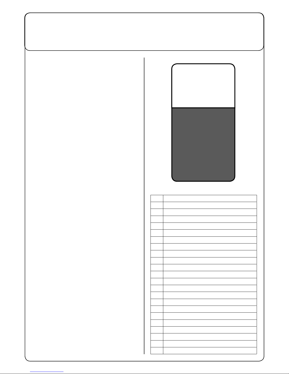
After the removal of
all the packaging,
carefully open and
check the contents
● Owner Manual
● Battery Charging Lead
● Key Switch
● 2 x 40 Amp Fuse
● Maxi Fuse-puller
PLEASE
READ
BEFORE
COMMENCING
OPERATION
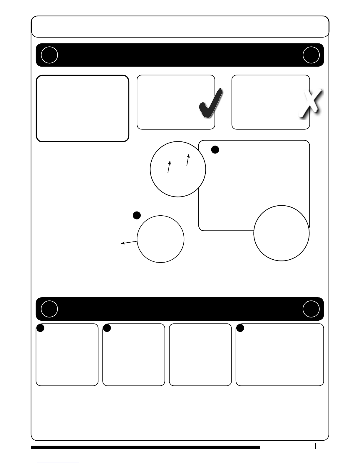
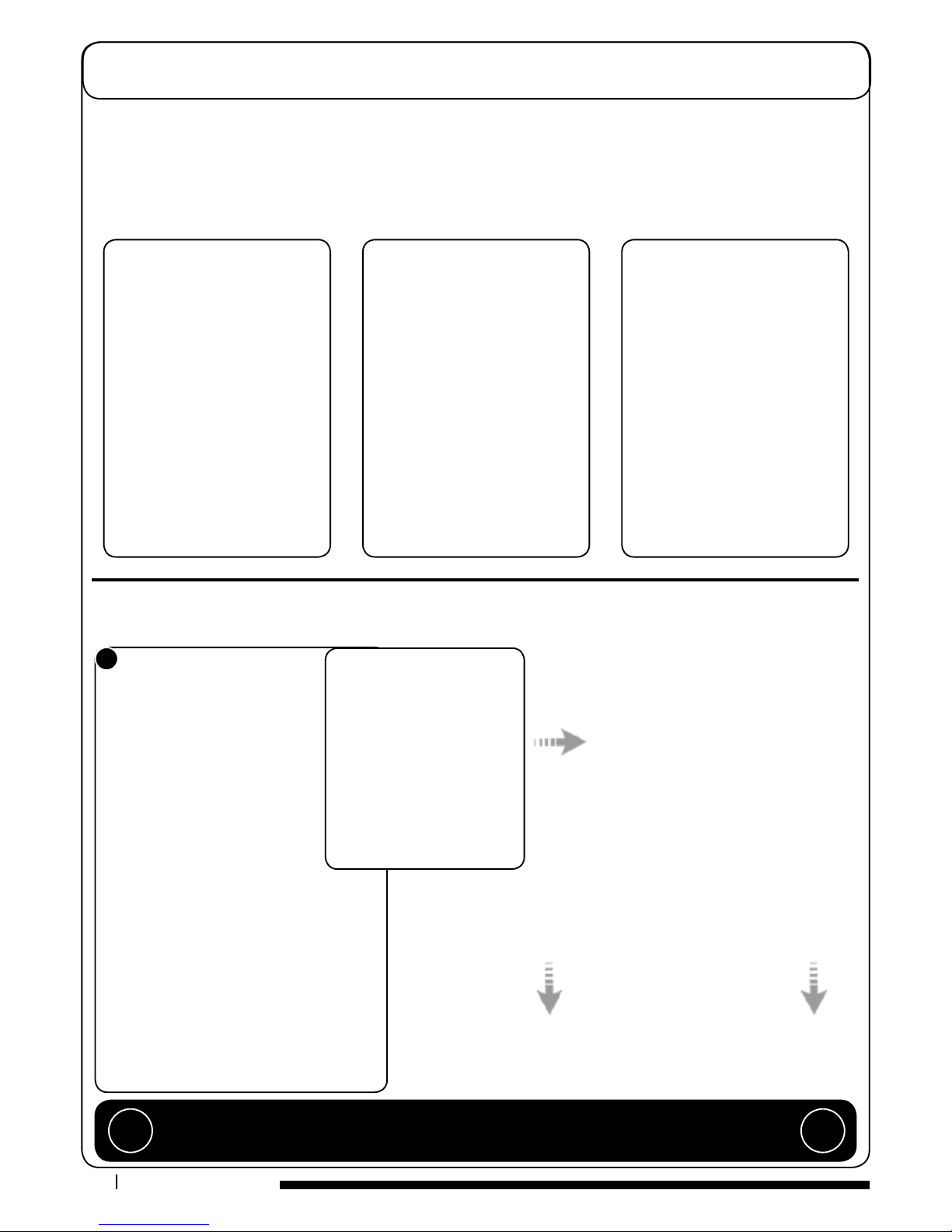
1Operator control panel
2Brush load adjuster knob
3Brush deck release lever
4Brush deck foot pedal
5Clean water tank ll point
6Side pod and skirt
7Brush deck motors x 2
8Side pod release lever
9Floor-tool raise / lower lever
10 Seat adjustment lever
11 Separator release catches
12 40 Amp battery fuses x 2 (4 Battery Machine)
13 Gel batteries
14 Charger
15 Accelerator pedal
16 Clean-water tank emptying hose
17 Semi parabolic oor-tool
18 Vacuum hose
19 Waste-water emptying hose
20 Floor-tool vacuum hose
21 Air separator assembly
22 Pedestrian warning light
23 Water Pump
TRO 650 / 200T
Machine Overview ................................ Pages 2-3
Control Panel Overview ................................ Page 4
Machine Set up Guide ................................ Pages 5-10
Fitting the Floor tool ................................ Page 6
Fitting the Hose ................................ Page 7
Breakaway Floor tool Feature ......................... Page 7
Fitting the brush ................................ Page 8
Filling the Clean Water Tank ............................ Page 8
Maximum Speed Control ................................ Page 9
Emergency Stop Button and Horn ................ Page 9
Adjusting the Seat .............................. Page 9
Raise / Lower Brush Deck ............................. Page 10
Raise / Lower Floor-Tool ................................ Page 10
Setting the Cleaning Controls ......................... Page 11
Fill Level Indicator ................................ Page 11
Brush Pressure Adjustment............................. Page 11
Hi / Lo Vacuum Setting ................................ Page 12
Machine Cleaning ................................ Page 13
Changing Floor tool Blades............................. Page 14
Machine Charging ................................ Page 15
Battery Care ................................ Page 16
Free-Wheel Function ................................ Page 13
Changing Floor tool Blades............................. Page 14
Machine Charging ................................ Page 15
Battery Care ................................ Page 16
Free-Wheel Function ................................ Page 17
O-aisle Cleaning Kit ................................ Page 18
Warning Lights ................................ Pages 19-20
Trouble Shooting ................................ Page 21
Specications ................................ Page 21
Rating Label / Personal Protective Equipment /
Recycling ................................ Page 22
Safety Precautions ................................ Pages 23-24
Recommended Spare Parts .......................... Page 25
Schematic Diagram ................................ Page 25
Battery Wiring ................................ Page 26
EU Declaration Document ............................. Page 27
Warranty ................................ Page 28
Company Address ................................ Page 32

Machine Overview
13 14
6
12
22
21
18 19 20
16
17
11
10
9
2
3
4
5
6
7
8
15
23

Control Panel Overview
RIDE ON SCRUBBER DRYER
TRO 650 / 200T
1Battery Charge Level Meter 8Emergency Stop
2Brush Operation / Load Indicator 9Horn Button
3Water Flow Rate Indicator 10 Maximum speed control
4Waste-water ‘Full’ Indicator 11 Traction Status Indicator
5O Aisle Vacuum Button 12 Charging status light
6Main control On / O key 13 Hours Meter
7Forward / Reverse Switch 14 Vacuum Hi / Lo Button
In the event of a breakdown contact
your Numatic dealer or the
Numatic Technical
help line +44 (0)1460 269268
10
4
9
3
8
2
7
1
11
5
6
12
13
14

Machine Set-up Guide
5
T 01460 68600
Lift top tank assembly to reveal battery compartment.
Always lift between points as illustrated to ensure personal safety.
Fit battery fuses (contained in start-up pack) into the battery fuse holders as illustrated (Fig.1).
Remove transit block from pallet (Fig.2).
1
2
5
Insert key into main control (on / o) and turn quarter-turn clockwise to position (1) ‘On’ (Fig.3).
Ensure that the forward / reverse switch is set to forward (Fig.4).
Depress accelerator pedal with right foot and slowly drive machine o of the pallet using the ramp
provided (Fig.5).
Note: The seat is tted with a pressure sensor that disables the machine until
an operator is seated.
When the machine is removed and in a safe position, turn key back to the position (0) ‘OFF’ (Fig.6).
4
3
PLEASE READ BEFORE COMMENCING ANY OPERATION AFTER THE REMOVAL OF ALL
THE PACKAGING, CAREFULLY OPEN AND CHECK THE CONTENTS. !!
NOTE: ENSURE THAT NO METAL OBJECTS COME INTO CONTACT WITH BATTERY
TERMINALS WHILE THE BATTERIES ARE EXPOSED.
WHEN INSERTING THE FIRST FUSE YOU MAY NOTICE A SPARK, THIS IS NORMAL. !!
CONTENTS
1 x Owner Manual
2 x Battery Charging Lead
2 x Keys
3 x 40 Amp Fuse (1 spare)
2 x Side pod skirts
1 x Brake disengage key
1 x Maxi Fuse-puller

Machine Set-up Guide
6
www.numatic.co.uk
Fitting the Floor-tool
To t the side pod skirts, rst remove the steel retaining strip already tted to the pod (Fig.7).
Align the steel retaining strip within the locating grooves of the rubber skirt and ret using existing screws (Fig.8)
Periodically the side skirts should be examined and checked for wear and damage. Replace as shown above.
Lower the oor-tool arm by moving the release lever to the upper position (Fig.9).
Push oor-tool onto the holder and secure with the easy-t securing pin (Fig.10).
Push waste collection pipe onto the oor-tool; ensure a tight t (Fig.11).
Note: Raise oor-tool again before driving to the cleaning area.
7
8
9
10
11
ALWAYS ENSURE THAT THE MACHINE IS SWITCHED OFF
BEFORE MAKING ANY ADJUSTMENTS !!

Machine Set-up Guide
7
T 01460 68600
Breakaway Floor-tool
The vacuum hose has a U-bend clip which creates a U-bend in the hose preventing water spillage when the vacuum is switched o. If
you need to remove the U-bend clip for any reason always ensure it is retted correctly before you resume operation.
Ret vacuum hose to the Floor-tool when nished.
Fitting the Hose Guide
The oor-tool design incorporates a safety knock-off feature.
Allowing it to safely disengage from its mounting should it become caught on an obstruction, during forward
machine movement.
To re-attach the oor-tool blade to its holder.
First loosen the retaining knobs on the oor-tool body and slide onto the holding bracket.
Tighten retaining knobs to nger tight. (See Fig.13).
13
Note:
DO NOT push the vacuum hose onto the Floor-tool with the Floor-tool in the raised position. !!

Machine Set-up Guide
8
www.numatic.co.uk
Featuring the OBS (Octagonal Brush System);
the brushes simply push-t up onto the chucks
making tting and removal a simple process.
Pull the side pod adjustment lever and set to the top position (Fig.14).
The side pod will now pull open (Fig.15).
Fit outer brush next on both sides (Fig.16).
Close side pod.
Safety gloves are recommended for the changing of used brushes.
Fitting the Brushes
14
15
16
The TRO 650 / 200T is equipped with a large capacity 120 litre clean-water tank allowing, for large areas to be covered
in a single ll. To ll the clean-water tank, lift the cover ap (Fig.17) to expose the ller cap.
Unscrew the ller cap (Fig.18) and ll the tank using a hose (Fig.19) or preferred method.
Filling the Clean-water Tank
17
18
19
The water level in the clean-water
tank can be measured using the
scale on the rear of the machine
(Fig.20).
Always ensure that the waste-water
tank is empty before lifting.
20
Note: Great care must be taken to ensure that contaminants (leaves, hair, dirt, etc.) are not
allowed to enter the clean-water tank during the lling process. If using a bucket or similar,
ensure it is always clean and free from debris. !!
Fill-level indicator

Machine Set-up Guide
9
T 01460 68600
The machine is now ready to be driven to the cleaning site.
Before performing the cleaning operation, place out appropriate warning signs and sweep or dust-mop the oor.
Use the maximum speed control knob and set desired
traction speed as required, depending on oor type and level
of soiling.
Middle speed is the optimum cleaning speed for most types
of oors.
Once the Max speed has been set using the control knob on
the control panel, ne adjustments can be made using the
variable control speed pedal located on the right side of the
footplate.
Maximum Speed Control
Emergency Stop Button and Horn The TRO 650 / 200T is equipped with an electronic braking system.
Simply lift your foot from the accelerator and the machine will stop.
In an emergency, strike the emergency-stop isolator button
The machine will be disabled.
To reset, turn isolator button clockwise (see Fig.21).
After resetting the emergency stop button, to restart the
machine, turn the ignition key to (0) ‘OFF’ then to position
(1) ‘ON’ again.
The horn is located on the right-hand side of the operator control
panel (see Fig.22).
21
22
Sitting in the driving position, adjust
the seat forwards or backwards as
necessary by using the lever found on
the left-hand side (see Fig.23).
Note: The seat is tted with a
pressure sensor that disables the
machine until an operator is seated.
Adjusting the Seat
IMPORTANT
Do not operate machine unless the Operator Manual has been read and fully understood. !!

Machine Set-up Guide
10
www.numatic.co.uk
Lowering the Floor-tool
27
After preparing the oor (see previous section), we are now ready to set the controls to suit the cleaning conditions.
Before any settings can be applied, ensure the brush deck is lowered.
While depressing left-hand foot pedal (see Fig.24), press down the release lever (see Fig.25) and gently release the foot
pedal to lower the brush deck (see Fig.26).
Lowering the Brush Deck
Note:
DO NOT push the vacuum hose onto the Floor-tool with the Floor-tool in the raised position. !!

Machine Operation
11
T 01460 68600
Insert the key into the ignition and quarter-turn it clockwise to position (1) ‘ON’.
The battery charge-level indicator will illuminate.
Setting the Cleaning Controls
Waste-water Tank Fill Level Warning Light
When the waste-water tank becomes full, a red warning light will
illuminate on the operator control panel (as illustrated) and the
vacuum motor will stop automatically.
The waste-water tank requires emptying (see page 16).
The machine is equipped with a brush-pressure load-warning system.
If the brush load increases due to changing oor types, the pressure can be
adjusted manually by the operator using the adjuster knob found on the left hand
side of the control column.
Turn it anti-clockwise to decrease load on the brushes and clockwise to increase
load/pressure on the brushes (see Fig.28).
Note: The run-time of the machine may decrease
if the load on the brushes is increased.
Brush pressure / Load adjustment
28
Note:
The run-time of the machine may decrease if the load on the brushes is increased. !!

Machine Set-up Guide
12
www.numatic.co.uk
Note: Care must be taken to reduce speed when
cornering or when manoeuvring around obstacles..
Machine In Use
To operate, select forward or reverse, press the accelerator pedal.
Vacuum pick-up and water-ow will turn on if selected and the brush and oor
tool are in the lowered position, the machine will move forward.
The clean water is dispersed evenly via ‘THRU- FEED’
scrubbing brushes.
The waste water is then retrieved by the suction oor-tool
(see Fig.29). Overlap each scrubbing path by 10cm to ensure
an even clean.
Do not operate the machine on inclines that exceed 11%.
If streaking occurs wipe oor-tool blades clean.
On heavily soiled oors use a ‘double scrub’ technique.
First pre-scrub the oor with the oor-tool in the raised position,
allow the chemical time to work then scrub the area a second time
with the oor-tool lowered.
Hi / Lo Vacuum Mode Selection
29
The TRO 650 / 200T has been tted with a Hi - Lo function, this reduces the
noise produced by the vacuum motor.
To operate the Hi - Lo mode start the machine in the normal way.
When the machine is running normally the Hi - Lo light will be illuminated Blue
This means the Vacuum motor is running at 100%.
With the machine running press the Hi - Lo button once the Vacuum motor will
reduce its speed to 75% of capacity and the Hi - Lo light will NOT illuminate
Blue.
ALWAYS ENSURE THAT THE FLOOR IS PRE-SWEPT
AND RELEVANT SAFETY SIGNS ARE DISPLAYED !!

Machine Cleaning
13
T 01460 68600
After use, empty waste-water tank using emptying hose
and ush-out with clean-water.
Next remove oor-tool vacuum hose and ush out
with clean-water.
Next empty clean-water tank, using emptying hose
and again ush out with clean-water.
A
A
B
C
B
C
Before removing
separator, rst pull-o
connected hoses.
Whilst pressing in the
separator toggles, remove hood
and rinse using clean-water.
The hood also has a
sealing-rubber which should be
examined at every
clean-down.
Remove white lter and rinse using clean-water, and ret.
IMPORTANT:
Never use the machine without the recommended lter as it may cause damage to the
machine.
Remove debris basket lter and rinse using clean-water, and ret.
IMPORTANT:
If the debris basket is allowed to become clogged, vacuum performance can deteriorate.
Located in your waste-water (top) tank is a full tank switch, this stops your machine from
working once the waste-water reaches its maximum limit. Sometimes the switch gets clogged
and blocked, clean to ensure correct operation.
The secondary clean-water tank lter is located to the rear of the
battery compartment, and should be checked at regular intervals.
Lift white plug and remove the lter, rinse and ret.
Ensure tank has been emptied and care is taken when working in
the vicinity of batteries.
The clean debris basket lter is located under the ller cap.
Remove debris basket lter and rinse using clean-water, and ret.
ALWAYS ENSURE THAT THE MACHINE IS SWITCHED
OFF PRIOR TO ANY MAINTENANCE. !!
NOTE: ANY SPILLS SHOULD BE
WIPED-UP BEFORE TANK IS LOWERED. !!

14
www.numatic.co.uk
The Floor Tool
31
32
Floor-tool overview
1. Floor-tool main body
2. Rear blade
3. Blade carrier
4. Front blade (slotted)
5. Retaining pins x 4
1
2
3
4
5
To clean the oor-tool, remove securing-pin and disconnect the lifting strap and remove the oor-tool securing pin
pull-free the oor-tool from the rear of the machine.
Rinse the oor-tool assembly with clean water and ret.
Periodically the oor-tool blades should be examined and checked for wear and damage.
The blade removal is easy. Simply start by removing the four retaining pins (see Fig.30), turn the oor-tool over and
separate the blade carrier from the body (see Fig.31). Peel away the blades from their locating lugs (see Fig.32) and
examine or renew as required. Replacement is a reversal of the removal process.
The TRO 650 / 200T is provided with the aluminium oor-tool shown.
30
Changing the Floor Tool Blades
ALWAYS ENSURE THAT THE BATTERY IS DISCONNECTED
PRIOR TO ANY MAINTENANCE !!
Note: Floor Tool adjusters are factory set for optimal performance.
The blades are designed to be reversible, thus extending their useful working life. !!

Machine Charging
15
T 01460 68600
The large capacity gel batteries are sealed for life and are totally maintenance free.
The on-board charger automatically monitors the charging process and will switch o
when the batteries are fully charged.
The machine charging point is located under the top tank. (see Fig.34).
Insert the charging lead required for your country into the charging point
and connect to a suitable power supply (see Fig.35).
Once the charging lead has been connected the red charging indicator will illuminate
(g.36) and the display panel will show ‘INHIBITED’ and the battery level display lights will
ash in unison.
The machine will not operate.
To ensure a full charge, the machine should be left for a period of 8 hrs.
Once fully charged, disconnect the charging lead from both the power supply and the
machine.
The battery meter displays the charge level of the batteries; when fully charged, all meter
lights are illuminated (see Fig.33).
As the machine is used and the batteries are discharged, the meter lights will go out
from right to left.
If the battery-charge level is allowed to discharge to the point that only the red light
remains illuminated, the operator must consider charging the machine.
If the battery-charge level is allowed to discharge to the point that only one red light remains
illuminated (and begins to ash), all cleaning functions will automatically be disabled and the
operator should drive the machine straight to a suitable charge point.
33
34
35
36
Always ensure that the machine is switched o prior to charging. !!

Battery Care
16
www.numatic.co.uk
To ensure your machine remains at its maximum eciency and prolong your battery life,
please follow the simple steps below:
Under normal daily usage:
Recharge batteries after each use regardless of machine operation time.
Recharge the machine fully after its
last use. Do not leave the machine in a
discharged state.
Batteries should be recharged every three months.
Charge fully the day before you start using the machine again.
Under abnormal use; i.e. leaving the machine without charging
for a period of time, we advise that you follow these steps:
If the machine will be standing unused for a period of 30 days or more, then
batteries must be fully charged and battery fuses removed using the Maxi
fuse-puller provided, prior to this period.
Periodicly inspect the battery connectioins for tightness and corrosion
Signal (LED) Meaning
Red LED on First Phase (constant current Mode)
Orange LED on Second Phase (Constant Voltage Mode)
Green LED on Third Phase (Constant Voltage Mode) Charge Complete
Red LED ashing
followed by Pause
Cooling Fan Locked > 1 ash between pause
Over Voltage Protection / Output Short Circuit / Battery
Reverse Polarity > 2 ashes between pause
Over Temperature Protection > 3 ashes between pause
Charge Time has exceeded 16 hrs during phase 1 or 2 >
4 ashes between pause

Free-wheel Function & Towing
17
T 01460 68600
The TTV 678 is equipped with a free-wheel
function that will enable the operator to move /
tow the machine. The motor brake is disengaged
by opening the brake arm on the side of the drive
wheel (see Fig.41).
Your start-up kit includes a brake drive disengage
key (329945, see Fig.42) which can be inserted
between the brake arm and drive housing
(see Fig.43).
41
42
Once the key has been inserted (see Fig.43)
the motor brake will be fully disengaged.
The machine will now be in full free-wheel mode.
43
46
When towing the machine ensure that a suitable
tow bar is used.
Care must be taken when towing; WHEN TOWING
DO NOT EXCEED AVERAGE SPEED OF 3 KPH.
The machine can be towed from the front bar as
indicated (see Fig.46).
Undo and remove the two retaining knobs (g.A&B).
Pull the power connector block apart and ret the
two retaining knobs.
When destination place reached, remove brake
disengage key, connect power plug, t fusses
44
45
A B
ALWAYS ENSURE THAT THE MACHINE IS ON LEVEL GROUND BEFORE
DISENGAGING BRAKE ARM. NEVER DISENGAGE THE BRAKE WHEN
THE MACHINE IS ON A SLOPE / GRADIENT. NEVER TOW THE MACHINE WITH THE
BRAKE ENGAGED AND POWER PLUG CONNECTED! remove battery fuses !!
WARNING!
WHEN THE BRAKE IS DISENGAGED AND POWER PLUG IS DISCONNECTED THE MACHINE IS IN
FREE-WHEEL MODE AND HAS NO BRAKE FACILITY, WHEN TOWING THE MACHINE
ENSURE THAT A SUITABLE TOW BAR IS USED.
Remember to remove the brake disengage key when you reach your nal destination / before using the machine.
NOT FOLLOWING DESCRIBED METHOD COULD DAMAGE MAIN CONTROL UNIT AND VOID THE WARRANTY
!!

Off-Aisle Cleaning Kit (Optional Extra Accessory)
18
www.numatic.co.uk
The optional off-aisle cleaning kit gives added exibility to the operator.
The kit can be used to clean hard to reach / inaccessible areas.
To operate the vacuum, press the off aisle vacuum button on the control panel (g.41).
Pressing the Off aisle Button again will switch the vacuum off.
The machine will need to be reset for normal use, when nished using the off-aisle kit.
Return the hose to the oor-tool once nished using the off-aisle facility (g.42).
41
Off-Aisle Accessory Kit
(Optional) (606182)
42
In the event of a breakdown contact your Numatic dealer or the
Numatic Technical helpline +44 (0)1460 269268
(See back page for company addresses or dealers stamp) !!

1 Flash with pause Batteries voltage low Batteries not been charged
Possible bad connection between
batteries, controller, charger or fuses
caused by loose connections ,
damaged wiring , water ingress
Not accepting charge due to faulty
battery/cell
Charger not functioning
Operating time
severely reduced
or machine will not
operate
Check when machine last charged
Switch OFF the machine :
Remove Fuses
Check connections to batteries, charger and fuses
for loose wires or screws
Check each battery Voltage individually to detect
defect unit 10.5V min
Check battery voltage and charge current
ensuring charger red fault light is
extinguished.
Charge batteries immediately
Tighten loose connections and
replace damaged components
Replace batteries as required
Replace charger
Contact
Service
Agent
2 Flashes with pause Traction motor
disconnected
The motor has a bad connection
Motor disconnected
TCO activated
(Thermal cut Out)
Motor failed open circuit
Motor will not operate Check all connections and leads between the motor
and controller
Tighten loose connections and
replace damaged
components.
3 Flashes with pause Traction motor wiring
Trip
The motor has a short circuit to a
battery
Motor will not operate Check all connections and leads between the motor and controller
4 Flashes with pause Battery Lockout The battery charge level has fallen
below the battery lockout level and
the controller is inhibiting machine
functions
Machine functions not
working
Check battery voltage and charge current
ensuring charger red fault light is extinguished.
Check each battery Voltage individually to detect
defect unit 10.5V min
Charge batteries immediately
6 Flashes with pause Charger Connected The controller is being inhibited from
driving, This may be because the
battery charger is connected
Machine functions not
working
Remove Charger to operate machine
8 Flashes with pause Controller Trip A controller trip is indicated Machine functions not
working
Check all connections and leads Tighten loose connections and
replace damaged components
9 Flashes with pause Brake Deactivated
or
Failed.
Poor brake connections.
Brake failure or deactivation.
Traction drive
disabled.
Check brake wiring and brake lever. Replace brake or wiring as
necessary.
Reactivate brake by engaging
brake lever.
10 Flashes with pause High Battery Voltage Poor connections between battery
controller and traction motor
Machine functions not
working
Check each battery Voltage individually to ensure
voltage < 14 volts
Check connections on controller
batteries and traction motor
Check combined battery pack voltage is < 28 volts
Green Status Indicator Fault Possible Cause Effect on Product Investigate the Following Action Required If fault persists
Green Flashing Warning light.
Warning light ashes explained

LCD Display Fault Possible Cause Effect on Product Investigate the Following Action Required If Fault
Persists
Blank * No power * Key switched off
* Emergency stop pressed
* Machine will not operate * Key switched off
* Emergency stop pressed
* Switch key on
* Release emergency stop
‘OVER CURRENT’ * Brush over current * Brush pressure too great.
* Brush current exceeds 32A
* Wrong type of brush for surface
* Vac. Brush, water &
Detergent motors / pump
will not operate
* Brush LED’s all ash in
unison until the Pedal is
released
* Release brush pressure
* Change type of brush
* Restart machine
‘UNDER VOLTS’ * Battery voltage dropped below
21 Volts
* Left most Battery LED ashes
* Batteries require recharging
* Faulty cell on battery
* Machine will not operate * Battery leads and connections * Charge Batteries
* Replace battery (if cell damaged)
‘ TANK FULL’ * Waste (Top) Tank full requires
emptying
* Waste Tank Float switch activated
whilst cleaning or off-aisle mode
selected
* Faulty Float switch
* Vac, Brush, water &
Detergent motors / pump
will not operate
* Waste (Top) Tank full LED illuminated
* Top waste tank full
* Empty Waste (Top) Tank
* Replace oat switch
‘INHIBITED’
MACHINE INHIBITED - NO OPERATION
Contact Service Agent
To view TRO 650 / 200T run-time information turn the key to position (1) ‘ON’.
Press the run-time information button to cycle between the different modes.
T = Total run-time.
V = Vacuum total run-time.
B = Brush total run-time.
W= Water Pump total run-time.
LCD Display
Table of contents
Other Numatic Scrubber manuals

Numatic
Numatic TTV - 4555/100T User manual

Numatic
Numatic TT 516 User manual

Numatic
Numatic TT-3450S Guide

Numatic
Numatic TTV 5565 User manual

Numatic
Numatic CRO 8055/100T User manual

Numatic
Numatic TT-4550S Guide

Numatic
Numatic TTB-3450/100S User manual

Numatic
Numatic HTB 1840 User manual

Numatic
Numatic TTB-4500/100S Guide

Numatic
Numatic NUC244NX User manual

Numatic
Numatic TT 1840 User manual

Numatic
Numatic TGB 516NX User manual

Numatic
Numatic TTB 1840 User manual

Numatic
Numatic HT4045 User manual

Numatic
Numatic CRO 8072 User manual

Numatic
Numatic TT6650G User manual

Numatic
Numatic TT 6650S User manual

Numatic
Numatic HGB 3045/55 User manual

Numatic
Numatic TT 1535S User manual

Numatic
Numatic NX300 User manual