Advanced Diagnostics FUTURA PRO ONE ABUS User manual

Operating Manual
Original Instructions
D446729XA
vers. 1.0
FUTURA
PRO
ONE
FUTURA
PRO
ONE ABUS®

INDEX
USE OF THE MANUAL.......................................................................................................................1
GENERAL WARNINGS.......................................................................................................................4
1 MACHINE DESCRIPTION............................................................................................................................5
1.1 MAIN OPERATING PARTS ................................................................................................................6
1.2 SAFETY..............................................................................................................................................7
1.3 TECHNICAL DATA..............................................................................................................................8
1.4 ACCESSORIES PROVIDED..............................................................................................................9
2 HANDLING..................................................................................................................................................10
2.1 PACKING..........................................................................................................................................10
2.2 UNPACKING.....................................................................................................................................10
2.3 HANDLING THE MACHINE..............................................................................................................10
3 MACHINE INSTALLATIONAND PREPARATION.......................................................................................11
3.1 CHECKING FOR DAMAGE..............................................................................................................11
3.2 ENVIRONMENTAL CONDITIONS....................................................................................................11
3.3 POSITIONING ..................................................................................................................................11
3.4 SEPARATE PARTS...........................................................................................................................12
3.4.1 TABLET STAND AND TABLET.................................................................................................................12
3.4.2 POWER PACK AND LEAD.......................................................................................................................13
3.4.3 FIXING BRACKET....................................................................................................................................13
3.5 WORK STATION DESCRIPTION ....................................................................................................14
4 TABLET REGULATION AND USE..............................................................................................................15
4.1 CHOICE OF LANGUAGE.................................................................................................................15
5 CLAMP FOR DIMPLEAND TRACK KEYS - 01R.......................................................................................16
5.1 FITTING THE KEY ...........................................................................................................................16
5.1.1 DIMPLE KEYS..........................................................................................................................................16
5.1.2 TRACK TYPE KEYS.................................................................................................................................17
5.2 REMOVING / FITTING CLAMP 01R ...............................................................................................17
5.3 REMOVING/FITTING THE JAWS ON CLAMP 01R ........................................................................18
5.4 USING TRACER 01T........................................................................................................................19
5.5 TRACER 02T....................................................................................................................................19
6 CLEANING..................................................................................................................................................20
7 MAINTENANCE..........................................................................................................................................21
7.1 OPERATIONS...................................................................................................................................21
7.2 ACCESS TO REAR COMPARTMENT .............................................................................................21
7.3 CUTTER AND/OR TRACER POINT REPLACEMENT.....................................................................22
7.4 TRACER 01T REPLACEMENT........................................................................................................22
7.5 CHECKING AND REPLACING FUSE..............................................................................................23
7.6 BATTERY REPLACEMENT..............................................................................................................24
8 DISPOSAL ..................................................................................................................................................25
SOFTWARE OPERATING GUIDE
ELECTRICAL DIAGRAMS
CE DECLARATION

USE OF THE MANUAL
This manual has been drawn up by the Manufacturer and is an integral part of the machine literature.
The manual gives information that is obligatory for the operator to know and which makes it possible to use the
machine safely.
User’s Manual
This user’s manual is provided because it is essential for proper use and maintenance of the machine.
The manual must be kept carefully throughout the life of the machine, including the decommissioning stage. Keep
in a dry place close to the machine where it is always to hand for the operator.
IT IS OBLIGATORY to read the manual carefully before using the machine.
Readers’ characteristics
This manual must be read and its contents acquired by those who will use it.
Manufacturer’s ID
FUTURA PRO ONE has an ID plate located on the back of the machine, showing the serial number.
Fig. 1
(*) see chap. 8 DISPOSAL.
Operating manual
Copyright Silca 2016 1

TERMINOLOGY
For those inexperienced in the subject of keys and key cutting, below is an illustration of the most frequently used
terms:
8
73
2
3
4
4
5
5
6
1 1
Fig. 2
1) Head
2) Neck 3) Shoulder stop
4) Blade
(stem) 5) Tip
6) Back 7) DIMPLE cutting
8) TRACK
cutting
ATTENTION: anodised aluminium dimple/laser keys, plastic keys or any other key without electrical
conductivity CANNOT BE decoded! For these types of keys digit the cuts directly or enter the indirect
code if the SSN in use allows it.
Operating manual FUTURA PRO ONE - FUTURA PRO ONE ABUS
Copyright Silca 2016
2

GRAPHICS IN THE MANUAL
Pay attention Obligation to read
the manual
GRAPHICS ON THE FUTURA PRO ONE KEY-CUTTING MACHINE
Do not clean with
compressed air Obligation to read
the manual Adhesive label
Mass - RPM
Operating manual FUTURA PRO ONE - FUTURA PRO ONE ABUS
Copyright Silca 2016 3

GENERAL WARNINGS
FUTURA PRO ONE is designed to the principles of European Standards (CE).
Right from the design stage solutions have been adopted to eliminate hazards for the operator in all the stages
of use: handling, regulation, use and maintenance.
Thematerials usedinmanufactureand the componentsemployedinusing FUTURAPROONEarenot dangerous
and ensure that the machine complies to current standards.
Silca S.p.A. has also experimented and applied numerous technical solutions that allow the key-cutting machine
to optimize the quality of the cut keys.
To guarantee maintaining these results over time, please follow the instructions below:
• Observe the procedures described in this manual;
• Always use Original Silca Tools as they are designed to make the best of FUTURA PRO ONE
and provide quality key-cutting;
• Use Silca/Ilco key blanks, made with top quality materials;
• Havethe key-cuttingmachine checked periodicallyby anauthorized SilcaAfter-Sales Service
Center (list at the end of this manual);
• Always use Silca Original Spare Parts. Beware of imitations!
NORMAL USE
FUTURA PRO ONE is a key-cutting machine and must be installed and used according to the rules and
specifications established by the manufacturer.
The FUTURA PRO ONE key-cutting machine is designed for use on business or industrial premises (e.g.
hardware shops, key cutting centers, etc...).
Any other use different from that indicated in this manual will cause the forfeiture of all customers’ rights to make
claims on Silca S.p.A. and may be an unknown source of hazard for the operator or third parties.
ATTENTION: Negligent use or failure by the operator to observe the instructions in this
manual are not covered by the warranty and the manufacturer declines any responsibility in
such cases.
ATTENTION: Anodised aluminium keys, plastic keys or any other key without electrical
conductivity CANNOT BE decoded!
RESIDUAL RISKS
No further risks will arise when properly using the FUTURA PRO ONE machine.
SAFETY REGULATIONS
• Always disconnect the machine when it is not in use or when performing maintenance
operations.
• Check the electrical wiring periodically; replace any wires that show signs of wear.
• Always work with dry hands free of grease or oil.
• Never tug on the electricity supply lead and make sure it is not in contact with oil or other
liquids, sharp objects or heat. Never remove the grounding pin from the plug. Check that the
ground wire is connected properly.
• Do not use the machine in dangerous environments (wet or damp).
• All visitors, especially children, must stay at a safe distance from the machine and must
never come into contact with the electric wiring.
Operating manual FUTURA PRO ONE - FUTURA PRO ONE ABUS
Copyright Silca 2016
4

1 MACHINE DESCRIPTION
FUTURA PRO ONE is an electronic machine operating on 3 axes with controlled movement.
Accurately studied, it adds a high degree of cutting precision to operating speed and ease of use.
FUTURA PRO ONE operates only when connected to a TABLET containing a Silca program.
It uses a tracer to decode keys with dimple and/or track cuts.
It can cut keys (in ferrous materials in general, brass, silver nickel, etc.) having:
• Dimple cuts
• Track cuts
• Special cuts (e.g. Ford Tibbe - with optional accessory)
• Cuts on tubular keys (with optional accessory)
FUTURA PRO ONE is used to cut the following types of keys:
Keys with DIMPLE and/or TRACK CUTS
FUTURA PRO ONE - FUTURA PRO ONE ABUS®
Fig. 3
FUTURA PRO ONE ABUS®
Abus®Bravus systems EC550 Abus® system (Silca ref.AB84)
Fig. 4
ATTENTION: Anodised aluminium keys, plastic keys or any other key without electrical conductivity
CANNOT BE decoded!
Operating manual FUTURA PRO ONE - FUTURA PRO ONE ABUS
Copyright Silca 2016 5
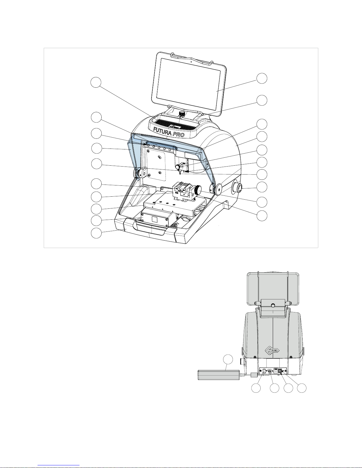
1.1 MAIN OPERATING PARTS
P
Q1
Q2
R
P1
A
B
G
J
J1
U
E
K
T
S
Z
C
L
G1
D
Fig. 5
A
- Tablet stand
B
- Tablet
C
- Safety shield
D
- Lamp
E
- Cover
G
- Cutter (Dimple/Track cuts)
G1
- Cutter shaft (Dimple/Track cuts)
J
- Tracer 01T
J1
- Tracer movement lever
L
- Tool compartment
K
- Swarf collection tray
P
- Clamp 01R (Dimple/Track cuts)
P1
- Clamp knob (01R )
Q1
- Left-hand jaw
Q2
- Right-hand jaw
R
- ON/Emergency push button
S
- X axis carriage
T
- Y axis carriage
U
- Z axis carriage
V
- Ethernet port
W
- Power pack
W1
- Power pack connector
Y
- USB port for Tablet charge
Y1
- USB port standard
Z
- Tool holder
VW1 YY1
W
Fig. 6
Operating manual FUTURA PRO ONE - FUTURA PRO ONE ABUS
Copyright Silca 2016
6

1.2 SAFETY
FUTURAPRO ONE is entirely built in compliance to the Machine Directives. The operations for which it has been
designed are easily carried out with no risk to the operator.
The adoption of general safety precautions and observation of the instructions provided by the manufacturer in
this manual eliminate all human error, unless deliberate.
FUTURA PRO ONE is designed with features which make it completely safe.
• Safety shield
The protective shield is designed to cover the working parts as completely
as possible, ensuring operator safety.
The shield (C) must be raised in order to fit keys for cutting or carry out
other operations (Fig. 7).
Raising the shield by means of a microswitch will deactivate the operating
and movement functions, including the cutter, and failed shield closing will
be notified with a special message on the tablet.
To re-activate the work cycle, lower the shield and follow the instructions
on the tablet.
Fig. 7
• Emergency stop
Use the red emergency button (R) (Fig. 5), located on the right-hand side of the machine to stop the machine
immediately in the event of serious malfunctioning or a hazard for the operator.
When the cause of the emergency has been eliminated, turn the button 45° clockwise to deactivate it.
NOTE: the operator is responsible for keeping the area around the button clear so that it can be
reached as quickly as possible.
C
Copyright Silca 2016 7

1.3 TECHNICAL DATA
Electricity supply: Machine: 24V d.c.- 5,5 Amp. - 130W
Power pack: 90/264V a.c. - 50/60Hz - 220W MEANWELL
GS220A24-R7B
Cutter motor: 24V d.c.
FUTURA PRO ONE
Cutter (Dimple cuts): 01D in HSS Super Rapid steel
Cutter (Track cuts): 01LW carbide, coated
FUTURA PRO ONE ABUS
®
Cutter (Dimple cuts): 01D and 07D in HSS Super Rapid steel
Cutter (Track cuts): 03L in HSS Super Rapid steel, coated
Tool speed: 12100 rpm
Movement: on 3 axes (with special bushes) driven by step motors (on rectified
roller guides)
FUTURA PRO ONE
Clamp 01R
(for Dimple/Track cuts)
removable and provided with interchangeable jaws:
01J - 02J
FUTURA PRO ONE ABUS®
Clamp 01R
(for Dimple/Track cuts)
removable and provided with interchangeable jaws:
01J - 02J
05J - 06J
29J - 30J
Runs: X axis: 30 mm Y axis: 50 mm Z axis: 27 mm
Dimensions: width: 318 mm
depth: 413 mm
height with tablet and stand: 522 mm (340 mm without tablet and
stand)
Mass: Kg. 17
Noise level: sound pressure Lp(A) =
-
brass dimple keys: 70.0 dB(A)
-
brass track keys: 74.0 dB(A)
-
steel track keys: 75.0 dB(A)
Operating manual FUTURA PRO ONE - FUTURA PRO ONE ABUS
Copyright Silca 2016
8

1.4 ACCESSORIES PROVIDED
FUTURAPROONEandFUTURAPROONEABUS®comewithasetofaccessoriesforoperationandmaintenance
(tools, hex wrenches...) supplied in a special tool kit comprising:
FUTURA PRO ONE - FUTURA PRO ONE ABUS®
stop bar cutter 01D Allen keys set 1,5 ÷ 5 mm
stylus touch pen tracer point 02T “T” allen key 2,5 mm
universal adapter fresa 01LW (only Futura PRO ONE) USB pen
slanted brush fuses 4 Amp.- delayed
Cutters and tracers on machine: Separately:
tracer point 01T fixing bracket
FUTURA PRO ONE ABUS®: additional accessories provided
cutter 07D 05J jaw 06J jaw
cutter 03L 29J jaw 30J jaw
01D
02T
Operating manual FUTURA PRO ONE - FUTURA PRO ONE ABUS
Copyright Silca 2016 9

2 HANDLING
The FUTURA PRO ONE key-cutting machine is easy to handle and there are no special hazards involved in
moving it.
The packed machine can by carried manually by one person.
2.1 PACKING
The packing for the FUTURA PRO ONE key-cutting machine ensures safe
handling of the machine and all its components.
Packing comprises expanded plastic material wrapped around the machine.
The robust cardboard box in which it is placed and the nylon wrapping protect
the machine even when stored for a long period.
Fig. 8
Keep dry Handle with care Up
The symbols on the outside of the cardboard box give indications for transport.
ATTENTION: keep the complete packing for future machine transfers.
2.2 UNPACKING
To remove the machine from its packing:
1) Cut the strapping with scissors and remove.
2) Open the box carefully without damaging it.
3) Free the machine from the protective shells.
4) Check the contents of the packing, comprised of:
-
FUTURA PRO ONE key-cutting machine
-
documentation comprising: user’s manual, spare parts sheet, specialist guide and warranty
-
tablet
-
tablet stand
-
power lead
-
power pack
-
tool kit
-
fixing bracket
2.3 HANDLING THE MACHINE
Once removed from its packing place FUTURA PRO ONE directly on the work bench; one person can easily
perform this operation.
ATTENTION: lift the machine by holding onto the base. Never lift the machine by gripping the
clamps, levers or other parts.
Operating manual FUTURA PRO ONE - FUTURA PRO ONE ABUS
Copyright Silca 2016
10

3 MACHINE INSTALLATION AND PREPARATION
Installation is the customer’s task and does not require any special skills.
The key-cutting machine is supplied ready for use and does not need calibration except for the tools to be used
and any additional jaws that are included with the machine; however, the operator is required to make certain
checks and prepare the machine for use.
NOTE: the machine is shipped with a steel rod installed in the cutter shaft to prevent the allen screw
from backing out during transit. REMOVE THE ROD AND INSTALL THE PROPER CUTTER PRIOR TO
ATTEMPTING TO CUT A KEY!
3.1 CHECKING FOR DAMAGE
FUTURA PRO ONE is a solid compact machine and will not break if handling, unpacking and installation are
carried out to the instructions in this manual. However, it is good practice to check that the machine has not been
damaged.
3.2 ENVIRONMENTAL CONDITIONS
To make the most of the key-cutting machine, bear in mind the following environmental parameters: it is advisable
for the area to be dry with good air circulation.
The optimum environmental conditions for machine operation are:
- temperature 10° C to 40°C;
- relative humidity: approx 60%.
3.3 POSITIONING
1) Place the key-cutting machine on a solid horizontal work bench suitable for the weight of the machine (17
Kg). The work bench should be approximately 100-120 cm high to facilitate access to the working parts. We
recommend leaving at least 30 cm clearance behind and around the machine to ensure good ventilation and
facilitate handling (Fig. 9).
2) Make sure machine voltage is suitable for the mains supply and that the latter is earthed with a differential switch.
3) Connect the power lead (power pack) to the machine (chap.3.4.2).
30 cm
100/120 cm
30 cm
30 cm
Fig. 9
Operating manual FUTURA PRO ONE - FUTURA PRO ONE ABUS
Copyright Silca 2016 11

3.4 SEPARATE PARTS
The machine packing also contains the following components, separately packed:
3.4.1 Tablet stand and tablet
Fig. 10 Fig. 11
These items are separate from the machine and must be unpacked and installed by the operator in the way
described below:
1) Remove the 2 items from their packing.
2) Loosen the knob on top of the machine cover (Fig. 12).
3) Install the tablet stand so that the special profile fits into the slot on the machine cover (Fig. 13).
4) Screw down and tighten the knob to secure the tablet stand to the cover (Fig. 14).
5) Fit the tablet into its stand (Fig. 15).
Fig. 12 Fig. 13
Y
Fig. 14 Fig. 15 Fig. 16
6) Connect the tablet USB/Micro USB cable to the USB tablet port (Y) located on the back of Futura PRO ONE.
Operating manual FUTURA PRO ONE - FUTURA PRO ONE ABUS
Copyright Silca 2016
12
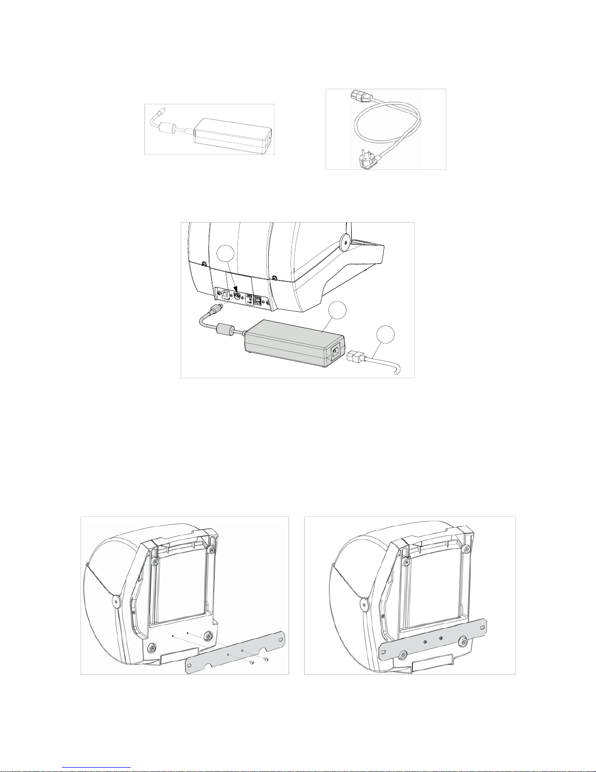
3.4.2 Power pack and lead
Fig. 17 Fig. 18
Connect FUTURA PRO ONE to the power pack (W) and connect the latter to the power supply with the power
lead (W2).
W
W2
W1
Fig. 19
3.4.3 Fixing bracket
If the key-cutting machine is transported and used on a vehicle, e.g. a van, it must be prepared as follows:
1) Turn off the machine and detach the power lead.
2) Remove the tablet holder and tablet.
3) Turn the key-cutting machine onto its back.
4) Connect
the fixing bracket to the machine and secure with the 2 screws.
5) Return the machine to its upright position on the work top.
Fig. 20 Fig. 21
Operating manual FUTURA PRO ONE - FUTURA PRO ONE ABUS
Copyright Silca 2016 13

3.5 WORK STATION DESCRIPTION
One operator is enough to operate the machine, which has the following operating parts:
• General ON/OFF/emergency button (R) located on the right-hand side of the machine
• Key holding clamp (P)
• Tablet (B)
• Tablet ON button (B1)
• Safety shield (C)
• Cutter (G)
P
R
B
G
C
B1
Fig. 22
Operating manual FUTURA PRO ONE - FUTURA PRO ONE ABUS
Copyright Silca 2016
14

4 TABLET REGULATION AND USE
1) Connect the tablet to a power source by means of its power pack in order to charge it (3 hours for the first
charge). The tablet can also be charged connected to the specific USB port (Y) on the back of the machine (Fig.
16, page 12).
2) Turn on the tablet by holding down the push button (B1) (Fig. 22) holding it down for a few seconds.
REGULATING TABLET INCLINATION
1) Loosen the knob (B2).
2) Incline the stand as required.
3) Tighten the knob (B2).
Fig. 23
4.1 CHOICE OF LANGUAGE
1) Select “Settings”.
2) Scroll up with your finger.
3) Select Language & Input and then Language (on the right).
4) Scroll and select the desired language (i.e. English United States).
5) Select Silca Keyboard (if desired)
6) Select Display > Sleep > Never. This will prevent the application from timing out and closing the session.
7) To quit:
• For all software functionalities on board the Silca key-cutting machine, see the SOFTWARE
OPERATING GUIDE on your tablet (Ch.10).
• Further instructions are given in the quick guide for the tablet.
Operating manual FUTURA PRO ONE - FUTURA PRO ONE ABUS
Copyright Silca 2016 15

5 CLAMP FOR DIMPLE AND TRACK KEYS - 01R
According to the type of key to be decoded and/or cut, follow the instructions in the Silca tablet program regarding:
• clamp
• use of jaws (Q1) and (Q2)
• clamp stop (Fig. 25 and Fig. 26)
5.1 FITTING THE KEY
The clamp is designed to house high security keys with shoulder stop
or tip reference.
For shoulder stop keys, place the shoulder of the key against the jaws
(stop “0”) (Fig. 25) and the others (tip stop) must be placed against
one of the grooves (1-2-3-4), as indicated in the Silca tablet program.
For this operation use the bar provided (Fig. 26).
NOTE: the stop bar must be removed before decoding or
cutting.
1) Fit the key to be cut into its seat and ensure it is resting firmly on
the clamp plate.
2) Tighten the knob (M) to secure the key.
Fig. 24
5.1.1 DIMPLE keys
0
Fig. 25 - SHOULDER STOP
1
2
3
4
Fig. 26 - TIP STOP
Q2Q1
Operating manual FUTURA PRO ONE - FUTURA PRO ONE ABUS
Copyright Silca 2016
16

5.1.2 TRACK type keys
0
Fig. 27 - SHOULDER STOP
1
2
3
4
Fig. 28 - TIP STOP
5.2 REMOVING / FITTING CLAMP 01R
1) Raise the safety shield.
2) Loosen the grub screw (P2) and remove the clamp by pulling it towards the operator.
3) Carefully clean the clamp support seat.
4) Clean the clamp before fitting into the support.
5)
Fit the clamp (with knob on the right) into the special dovetail and take up against the stop pin.
6) Tighten the grub screw (P2) to secure the clamp.
P2
Fig. 29
Operating manual FUTURA PRO ONE - FUTURA PRO ONE ABUS
Copyright Silca 2016 17

5.3 REMOVING/FITTING THE JAWS ON CLAMP 01R
1) Raise the safety shield.
2) Loosen the knob (P1) by a couple of turns (Fig. 30).
3) Use your fingers to pull the jaw to be removed out towards the operator (Fig. 31).
4) Carefully clean the seat of the jaw on the clamp.
5) Clean the jaw before fitting into the clamp.
6) Fit the jaw up against the stop pin.
NOTE: there is only one way to fit the jaw into the clamp.
P1
Fig. 30 Fig. 31
Operating manual FUTURA PRO ONE - FUTURA PRO ONE ABUS
Copyright Silca 2016
18
This manual suits for next models
1
Table of contents
Other Advanced Diagnostics Power Tools manuals

Popular Power Tools manuals by other brands

OEM Tools
OEM Tools 24665 Operating instructions and parts manual

BLACK DECKER
BLACK DECKER BDCINF18 Original instructions

Power Fist
Power Fist 8972283 user manual

Swisstech
Swisstech Micro-Slim 9-in-1 quick start guide

Power Tec
Power Tec 92559 manual

Gema
Gema OptiGun GA03-E Operating instructions and spare parts list


