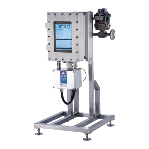
Advanced Sensors OIW-EX 1000 User manual

OIW-EX 1000 - Spectrometer Handbook
Code: OIW-HBO-0005 Version: EX-002
Date: 18 March 2010
Advanced Sensors Ltd,
www.advancedsensors.co.uk Tel: +44(0)28 9332 8922. FAX +44(0)28 9332 8669 Page 1 of 33
OIW-EX 1000
Oil in Water Monitors
Spectrometer Handbook
Document code: OIW-HBO-0005
Version: EX-002

OIW-EX 1000 - Spectrometer Handbook
Code: OIW-HBO-0005 Version: EX-002
Date: 18 March 2010
Advanced Sensors Ltd,
www.advancedsensors.co.uk Tel: +44(0)28 9332 8922. FAX +44(0)28 9332 8669 Page 2 of 33
Document History
1. Version A Draft..........First draft – separated from
installation and User Handbook 1st May 2007
2. Version B Draft..........Updated to reflect change to support the
v2 Spectrometer 3rd April 2009
3. Version C...................Preface page updated 12th June 2009
4. Version 1....................First Release after Review 29th June 2009
5. Version 2....................Updated in-line with Version 4 of the
OIW software 19th Jan 2010

OIW-EX 1000 - Spectrometer Handbook
Code: OIW-HBO-0005 Version: EX-002
Date: 18 March 2010
Advanced Sensors Ltd,
www.advancedsensors.co.uk Tel: +44(0)28 9332 8922. FAX +44(0)28 9332 8669 Page 3 of 33
Preface
This handbook is part of a library of handbooks that cover the full operation of the OIW-EX
Series of products. The table below indicates the handbooks available. Please ensure that you
have read all handbooks required for your job function.
Note: please ensure you have the latest version of these documents – password protected
copies of the documents together with a table of the latest revisions are available on-line at:
http://www.advancedsensors.co.uk/downloads
The passwords may be obtained directly from Advanced Sensors Ltd.
Handbooks Descriptions
Code Handbook Description OIW EX Model
OIW-HBO
100
1000
1000P
4000
0001 Installation
Hardware related details required for the physical
installation of the OIW-EX Series of units. 999
0002 User An overview of the operation of the OIW-EX Series of
products and details how to configure the unit. 9999
0003 Data Logging Information on how to access and examine the data log
and system log files. 9999
0004 Remote
Access How to control the OIW-EX Series of units remotely. 9999
0005 Spectrometer
Operation of the spectrometer and associated
Spectrometer files. 999
0006 Wireless
Controller Set up and use of the handheld wireless controller. O O O O
0007 Flush Valve
Operation of the OIW-EX Series of units when a Flush
Valve is fitted. O O O
0008 Dual Flow Operation of the OIW-EX Series of units when used in
a Dual Flow Mode. O O O
0009 Microscopy
Operation of the OIW-EX Series of units with
Microscopy files.
9
0010 Hart Operation of the OIW-EX Series of units with
supporting Hart. O O O O
0011 In-Line Probe
User Operation of the OIW-EX Series of units with an
In-Line Probe.
9
0012 In-Line Probe
Installation Installation of the OIW-EX Series of units with an
In-Line Probe.
9
Key
9= Required O = Optional

OIW-EX 1000 - Spectrometer Handbook
Code: OIW-HBO-0005 Version: EX-002
Date: 18 March 2010
Advanced Sensors Ltd,
www.advancedsensors.co.uk Tel: +44(0)28 9332 8922. FAX +44(0)28 9332 8669 Page 4 of 33
Table of Contents
1 OIW-EX 1000 - Spectrometer Handbook............................................................. 6
1.1 Introduction....................................................................................................6
1.2 Modes of Operation .......................................................................................6
1.3 Health & Safety..............................................................................................6
2 Spectrometer Overview ........................................................................................ 7
2.1 Identifying an OIW EX1000 Unit..................................................................8
2.2 Showing and Hiding the Spectrum................................................................9
2.3 Spectrum Reading Cycle..............................................................................10
2.4 Spectra Control Options...............................................................................11
2.4.1 Spectrometer Standard Creation..........................................................12
2.5 Spectrum Reading Cycle Explained............................................................14
2.5.1 Measuring Cycles Spectrum Operation...............................................14
2.5.2 PPM Level Triggered Spectrum Operation .........................................15
2.5.3 Manual Spectrum Operation................................................................15
2.6 Spectrum Control Options ...........................................................................16
2.6.1 Spectrum Smoothing............................................................................16
2.6.2 Spectrum Averaging ............................................................................16
2.6.3 Spectrum Integration Time..................................................................17
2.7 Spectrum Control Options ...........................................................................18
2.7.1 Water Status off/on ..............................................................................18
2.7.2 Changing % Mask Tolerance...............................................................19
2.7.3 Changing the Lower Wavelength ........................................................19
2.7.4 Changing the Upper Wavelength.........................................................20
2.7.5 Changing the Upper Wavelength.........................................................20
2.7.6 Changing the % Above Line................................................................21
2.8 Spectrum Log Files......................................................................................22
3 Using SpAn......................................................................................................... 24
3.1 Starting SpAn...............................................................................................24
3.2 Loading a spectrum log File ........................................................................25
3.3 Auto Scaling.................................................................................................28
3.4 Identifying Points on the Graph...................................................................29
3.5 Saving/Loading Spectral Data File Sets ......................................................29
3.6 Printing.........................................................................................................31
4 Errors with EX1000............................................................................................ 32
5 Appendix 1 – OIW-EX Series Contact Details................................................... 33

OIW-EX 1000 - Spectrometer Handbook
Code: OIW-HBO-0005 Version: EX-002
Date: 18 March 2010
Advanced Sensors Ltd,
www.advancedsensors.co.uk Tel: +44(0)28 9332 8922. FAX +44(0)28 9332 8669 Page 5 of 33
Symbols in this document
The following symbols are used in this document to indicate special information:
Warning – an instruction that draws attention to the risk of injury or death.
Caution – an instruction that draws attention to the risk of damage to the product,
process or surroundings.
Note – Clarification of an instruction or additional information.
Information – Further reference for more detailed information or technical details.
NOTE: although Warning hazards are related to potential personal injury, and
Caution hazards are associated with material damage, it must be understood that
operation of damaged equipment could lead to personal injury or death. All
Warning and Caution hazards must be complied with.

OIW-EX 1000 - Spectrometer Handbook
Code: OIW-HBO-0005 Version: EX-002
Date: 18 March 2010
Advanced Sensors Ltd,
www.advancedsensors.co.uk Tel: +44(0)28 9332 8922. FAX +44(0)28 9332 8669 Page 6 of 33
1 OIW-EX Series with Spectrometer fitted -
Spectrometer Handbook
1.1 Introduction
This spectrometer handbook provides user information on how to use and configure the
Advanced Sensors Ltd OIW-EX Series Oil in Water Monitor Systems spectrometer features
only – for all other features please refer to the User Handbook.
This manual relates to the functionality of the OIW-EX Series unit at software release v4 and
above.
CAUTION: This manual describes the operation and use of the spectrometer
features only NOT the installation. Ensure that the unit has been correctly installed
in line with the Installation Handbook prior to use.
1.2 Modes of Operation
The OIW-EX Series have been designed with maximum flexibility in mind enabling them to
be configured in a verity of ways to suit different customer requirements.
CAUTION: Should the equipment be used in a manner not specified in this
handbook the sensor may not function correctly and protection provided by the
equipment may be impaired.
CAUTION: No options should be altered without a full understanding of the change
being made.
1.3 Health & Safety
WARNING: This document relates to electrical equipment of substantial weight.
Health and Safety section of the Installation Handbook must be read carefully and
understood before using this equipment.
NOTE: although Warning hazards are related to personal injury, and Caution
hazards are associated with material damage, it must be understood that operation of
damaged equipment could lead to personal injury or death. Therefore all Warning
and Caution hazards must be complied with.

OIW-EX 1000 - Spectrometer Handbook
Code: OIW-HBO-0005 Version: EX-002
Date: 18 March 2010
Advanced Sensors Ltd,
www.advancedsensors.co.uk Tel: +44(0)28 9332 8922. FAX +44(0)28 9332 8669 Page 7 of 33
2 Spectrometer Overview
The OIW-EX Series fitted with a Spectrometer enhances the functionality of the standard unit
by incorporating an optical spectrum analyser unit which allows for enhanced analyses of the
produced water in the sample chamber.
The following OIW-EX Series models all have Spectrometer fitted as standard:
•OIW-EX1000,
•OIW-EX1000P and
•OIW-EX4000.
Advanced Sensors software suite includes SpAn. The SpAn software tool simplifies the
analysis of multiple optical scans.
As with all data logs generated by the OIW-EX Series of products the spectrum analyser files
are created in generates industry standard .csv file format allowing the user the flexibility to
analyse the data in a tool of their choosing.
The following sections will detail the operation of the spectrum analyser unit and will provide
details on how to use the SpAn software – details will also be provided on the file format
should the use wish to analyse the data with alternative tools.

OIW-EX 1000 - Spectrometer Handbook
Code: OIW-HBO-0005 Version: EX-002
Date: 18 March 2010
Advanced Sensors Ltd,
www.advancedsensors.co.uk Tel: +44(0)28 9332 8922. FAX +44(0)28 9332 8669 Page 8 of 33
2.1 Identifying an OIW EX Series Unit with a Spectrometer
The OIW-EX 100 software, see Figure 2, can be distinguished from the OIW-EX Series with
Spectrometer fitted, see Figure 1, primarily by the software header box, which clearly
identifies unit type in its header, shown below.
The following OIW-EX Series models all have Spectrometer fitted as standard1:
•OIW-EX1000,
•OIW-EX1000P and
•OIW-EX4000.
Figure 1. OIW-EX100 software
Figure 2. OIW-EX1000 software
The following sections will detail the operation of the spectrum analyser unit and will provide
details on how to use the SpAn software – details will also be provided on the file format
should the use wish to analyse the data with alternative tools.
1Though out the rest of this Handbook the term OIW-EX1000 is used; but this also covers all OIW-EX Series
with a Spectrometer fitted; i.e. OIW-EX1000, OIW-EX1000P and OIW-EX4000.

OIW-EX 1000 - Spectrometer Handbook
Code: OIW-HBO-0005 Version: EX-002
Date: 18 March 2010
Advanced Sensors Ltd,
www.advancedsensors.co.uk Tel: +44(0)28 9332 8922. FAX +44(0)28 9332 8669 Page 9 of 33
2.2 Showing and Hiding the Spectrum
The graph panel of the OIW-EX 1000 software will allow you to switch between showing the
oil ppm level, the spectrum of the oil or both, see Figure 3.
Figure 3. View of OIW EX1000 PPM/PPB and Spectrum
Clicking the “Spectra” button, see Figure 3c, when the oil ppm level is displayed, will display
the Spectra screen on view, see Figure 3d.
Clicking the “Hide” button, see Figure 3d, when Spectra view is displayed will display the oil
ppm level, see Figure 3c.
Clicking the button, see Figure 3e,when Spectra view is displayed will display the oil
ppm level and the Spectra, see Figure 3f.
Clicking the button, see Figure 3f,when the oil ppm level and Spectra are displayed will
display just the oil ppm level, see Figure 3c.

OIW-EX 1000 - Spectrometer Handbook
Code: OIW-HBO-0005 Version: EX-002
Date: 18 March 2010
Advanced Sensors Ltd,
www.advancedsensors.co.uk Tel: +44(0)28 9332 8922. FAX +44(0)28 9332 8669 Page 10 of 33
2.3 Spectrum Reading Cycle
As with the oil detection system the spectrum analyser requires the laser light as an
illumination source therefore the analyser will not operate when the measurement cycle is in
the stopped position.
The spectrum analyser can take a reading based on any one of three conditions:
•The OIW System software periodically requests a reading – based on a user selectable
time period;
•The PPM level rises above the “User Set” trigger level;
•The user manually requests a reading.
Each of these trigger conditions will be discussed in more detail below but the reading cycle
remains the same for each condition.
The user can have any combination of trigger conditions including all conditions at the same
time i.e. the system can be set to trigger a reading every hour and trigger a reading if 100ppm is
exceeded and select a manual reading. Note: only one reading will be taken at a time.

OIW-EX 1000 - Spectrometer Handbook
Code: OIW-HBO-0005 Version: EX-002
Date: 18 March 2010
Advanced Sensors Ltd,
www.advancedsensors.co.uk Tel: +44(0)28 9332 8922. FAX +44(0)28 9332 8669 Page 11 of 33
2.4 Spectra Control Options
The spectrum analyser controls can be accessed via the Oil Calibration Settings and
Configuration Options tabs once you have logged in to the configuration menu,
see Figure 4.
Figure 4. Spectrometer Controls
NOTE: if the spectrometer was not detected or if communications between the main
OIW system and the spectrum analyser are lost the Take Spectra button is replaced
with the word Fault.

OIW-EX 1000 - Spectrometer Handbook
Code: OIW-HBO-0005 Version: EX-002
Date: 18 March 2010
Advanced Sensors Ltd,
www.advancedsensors.co.uk Tel: +44(0)28 9332 8922. FAX +44(0)28 9332 8669 Page 12 of 33
2.4.1 Spectrometer Standard Creation
Under the Oil Calibration Settings tab is an option to create a Spectrometer standard. Future
Spectrometer reading may be compared with this standard and an alarm may be raised if the
composition of the oil changes significantly.
Figure 5. Scheduled Auto Settings
As with the oil detection system the spectrum analyser requires the laser light as an
illumination source therefore the analyser will not operate when the measurement cycle is in
the stopped position.
2.4.1.1 What is a Spectrometer Standard
A Spectrum Standard is the “overall shape” of the Spectra that is typical of the oil passing
though the OIW-EX Series Analyzer. Figure 7 show two spectra from oil samples, if
Sample 1 was set as the Spectrometer Standard then an alarm can be raised when
Sample 2 is encountered because its shape does not match the Spectrometer Standard.
Spectra From Two Oil Samples
0
10000
20000
30000
40000
50000
60000
70000
80000
370
389
408
427
446
465
484
503
522
541
560
579
598
617
636
655
674
693
712
731
750
769
788
807
826
845
864
883
902
921
940
959
978
997
1016
1035
Wave length (Nm)
Relative Intensity
Sample 1
Sample 2
Figure 6. Spectra from Two Oil Samples

OIW-EX 1000 - Spectrometer Handbook
Code: OIW-HBO-0005 Version: EX-002
Date: 18 March 2010
Advanced Sensors Ltd,
www.advancedsensors.co.uk Tel: +44(0)28 9332 8922. FAX +44(0)28 9332 8669 Page 13 of 33
2.4.1.2 Spectrometer Standard Creation Process
Before you start to create a Spectrometer Standard you need to specify the number of
Spectra you wish to form the Standard. This can be done with the Standard Size
control. Once you are happy with the standard size a click on the Create Standard
button will start the process; see Figure 7. The number of samples used to create the
Standard means that the Standard is more representative of the overall shape of the
samples passing though the analyzer. The default minimum of 5 will be fine in most
cases.
A new control Sample remaining until standard set will appear; this will be
decremented each time a sample is taken; see Figure 8.
Either leave for scheduled to run or to take a spectrometer standard just click the Take
Spectra button; see Figure 9. Repeat this process until all samples have been taken, see
Figure 11
Figure 7. Starting the Create Standard Process
Figure 8. Sample remaining until standard set
Figure 9. Take Spectra Button
Figure 10. Sample remaining until standard set decremented
Figure 11. Starting the Create Standard Process

OIW-EX 1000 - Spectrometer Handbook
Code: OIW-HBO-0005 Version: EX-002
Date: 18 March 2010
Advanced Sensors Ltd,
www.advancedsensors.co.uk Tel: +44(0)28 9332 8922. FAX +44(0)28 9332 8669 Page 14 of 33
2.5 Spectrum Reading Cycle Explained
As with the oil detection system the spectrum analyser requires the laser light as an
illumination source therefore the analyser will not operate when the measurement cycle is in
the stopped position.
The spectrum analyser can take a reading based on any one of three conditions:
•The OIW System software periodically requests a reading – based on a user selectable
time period;
•The PPM level rises above the “User Set” trigger level;
•The user manually requests a reading.
Each of these trigger conditions will be discussed in more detail below but the reading cycle
remains the same for each condition.
The user can have any combination of trigger conditions including all conditions at the same
time i.e. the system can be set to trigger a reading every hour and trigger a reading if 100ppm is
exceeded and select a manual reading. Note: only one reading will be taken at a time.
2.5.1 Measuring Cycles Spectrum Operation
The OIW EX-1000 can be set to take a spectrum analyser reading at regular Measuring Cycles
throughout the day, see the User Handbook for OIW EX-100 for details about Measuring
Cycles. To access this option navigate to the Configuration Options tab, click the
Schedule button and select the Spectrometer tab on the Schedule Configuration
window.
You may change the frequency at which Spectra are taken by using the
“Spectrometer reading taken every” XX “Measurement Cycles” control, Figure 12.
Figure 12. Scheduled Auto Settings

OIW-EX 1000 - Spectrometer Handbook
Code: OIW-HBO-0005 Version: EX-002
Date: 18 March 2010
Advanced Sensors Ltd,
www.advancedsensors.co.uk Tel: +44(0)28 9332 8922. FAX +44(0)28 9332 8669 Page 15 of 33
With the “Spectrometer reading taken every” XX “Measurement Cycles” set to 0; no
Spectra will be taken based on Measuring Cycles.
With “Spectrometer reading taken every” XX “Measurement Cycles” set to 1; a Spectra
will be taken every time a Measuring Cycle Starts.
2.5.2 PPM Level Triggered Spectrum Operation
The OIW EX-1000 can be set to take a spectrum analyser reading when the ppm reading
exceeds a user set ppm level. To access this option navigate to the Configuration Options
tab, click the Oil Type button and select the Spectrometer Settings tab on the Oil Type
Configuration window, Figure 13.
The Level Trigger Value allows any ppm level to be entered in the range 0 to 50000. If a value
of 0 is entered ppm level spectrum readings will not be taken as a value of 0 (zero) disables this
option.
Figure 13. Trigger Level Settings
2.5.3 Manual Spectrum Operation
With the measurement cycle started the Take Spectra button will be active and can be
selected at any time to trigger a spectrum analysis of the produced water at that time.

OIW-EX 1000 - Spectrometer Handbook
Code: OIW-HBO-0005 Version: EX-002
Date: 18 March 2010
Advanced Sensors Ltd,
www.advancedsensors.co.uk Tel: +44(0)28 9332 8922. FAX +44(0)28 9332 8669 Page 16 of 33
2.6 Spectrum Control Options
The spectrum analyser three parameters that control the quality of the Spectra:
•Smoothing,
•Averaging, and
•Integration Time.
To access this option navigate to the Configuration Options tab, click the Schedule
button and select the Spectrometer Settings tab on the Schedule Configuration
window, see Figure 14.
Figure 14. Spectrum Control Options
2.6.1 Spectrum Smoothing
Smoothing specifies the number of readings on either side of a particular reading to average
across an entire spectral acquisition. This method averages a group of adjacent detector
elements. A value of three, for example, averages each data point with three points (or bins) to
its left and three points to its right.
The greater this value, the smoother the data and the higher the signal-to-noise ratio. However,
if the value entered is too high, a loss in spectral resolution results.
2.6.2 Spectrum Averaging
Smoothing specifies the number of spectra to average for the specified spectra output. A higher
value for this parameter provides a better signal-to-noise (S:N) ratio.

OIW-EX 1000 - Spectrometer Handbook
Code: OIW-HBO-0005 Version: EX-002
Date: 18 March 2010
Advanced Sensors Ltd,
www.advancedsensors.co.uk Tel: +44(0)28 9332 8922. FAX +44(0)28 9332 8669 Page 17 of 33
2.6.3 Spectrum Integration Time
Integration Time specifies the length of the spectral acquisition in milliseconds for the
spectrometer. The integration time of the spectrometer is analogous to the shutter speed of a
camera. The higher the value specified for the integration time, the longer the detector "looks"
at the incoming laser light.
The three integration times relate to the different integration time available to avoid clip the
signal.
If IT1was set to 600ms, IT2 was set to 300ms and IT3 set to 200ms.
The OIW EX 1000 software would take a Spectra using IT1 and check for Spectral clipping.
If Spectral clipping occurred with IT1 then the OIW EX 1000 software would take a Spectra
using IT2 and check for Spectral clipping.
If Spectral clipping occurred with IT2 the OIW EX 1000 software would take a Spectra using
IT3.
Example of Different Integration Times
420
435
450
465
480
495
510
525
540
555
570
585
600
615
630
645
660
675
690
705
720
Wave length nm
Light Intensity
IT1 = 600ms
IT2 = 300ms
IT3 = 200ms
Figure 15. Spectral Clipping and Integration Times
If IT1, IT2 and IT3 are set to the same value then the OIW EX 1000 software does not attempt
to resolve Spectral clipping.

OIW-EX 1000 - Spectrometer Handbook
Code: OIW-HBO-0005 Version: EX-002
Date: 18 March 2010
Advanced Sensors Ltd,
www.advancedsensors.co.uk Tel: +44(0)28 9332 8922. FAX +44(0)28 9332 8669 Page 18 of 33
2.7 Spectrum Control Options
The spectrum analyser has three parameters that control the quality of the Spectra:
•Smoothing,
•Averaging, and
•Integration Time.
To access this option navigate to the Configuration Options tab, click the Schedule
button and select the Spectrometer Mask Settings tab on the Schedule Configuration
window, see Figure 16.
Figure 16. Spectrum Control Options
2.7.1 Water Status off/on
Water Status Alarm off
Water Status Alarm on
Figure 17. Spectrum Control Options

OIW-EX 1000 - Spectrometer Handbook
Code: OIW-HBO-0005 Version: EX-002
Date: 18 March 2010
Advanced Sensors Ltd,
www.advancedsensors.co.uk Tel: +44(0)28 9332 8922. FAX +44(0)28 9332 8669 Page 19 of 33
2.7.2 Changing % Mask Tolerance
Figure 18. Changing the % Mask Tolerance
2.7.3 Changing the Lower Wavelength
Figure 19. Changing the Lower Wavelength

OIW-EX 1000 - Spectrometer Handbook
Code: OIW-HBO-0005 Version: EX-002
Date: 18 March 2010
Advanced Sensors Ltd,
www.advancedsensors.co.uk Tel: +44(0)28 9332 8922. FAX +44(0)28 9332 8669 Page 20 of 33
2.7.4 Changing the Upper Wavelength
Figure 20. Changing the Upper Wavelength
2.7.5 Changing the Upper Wavelength
Figure 21. Changing the Lower Wavelength
Table of contents
Other Advanced Sensors Measuring Instrument manuals
Popular Measuring Instrument manuals by other brands

Quest Controls
Quest Controls TELSEC MP1 user guide
BRUEL & KJAER
BRUEL & KJAER 2236 Application note
Wohler
Wohler Smart Connect SC 660 operating instructions

PCB Piezotronics
PCB Piezotronics IMI SENSORS y635a01 Installation and operating manual

Niigata seiki
Niigata seiki MCD130-25 instruction manual
Jula
Jula 619-283 operating instructions
