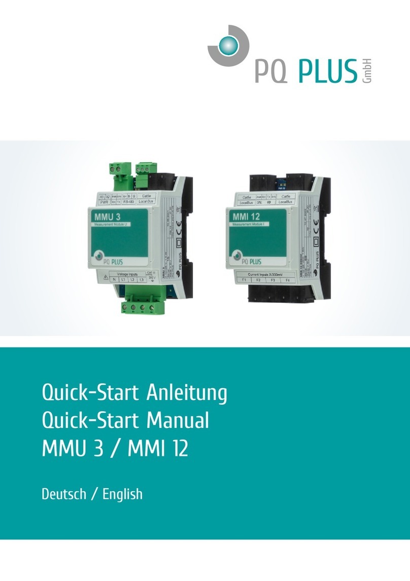
PQ Plus MMI 12RCM Instruction manual

• •
Quick-Start Anleitung
Quick-Start Manual
MMI 12RCM / MMI 12Flex / MMI 12DC
Deutsch / English

PQ Plus - MMI 12RCM / MMI 12Flex / MMI 12DCQuick-Start Anleitung
2
DE
Inhaltsverzeichnis
Installation................................................................................................4
Montage .......................................................................................................4
Spannungsversorgung .................................................................................5
Stromwandler anschließen ..........................................................................5
Inbetriebnahme......................................................................................8
MMI kongurieren ........................................................................................8
Anschluss und Einstellungen kontrollieren ..................................................9
Technische Daten................................................................................10

PQ Plus - MMI 12RCM / MMI 12Flex / MMI 12DC
3
EN
Quick-Start Anleitung
Table of Contents
Installation............................................................................................... 11
Mounting..................................................................................................... 11
Voltage supply ............................................................................................12
Connecting a current transformer...............................................................12
Commissioning...................................................................................... 15
Conguring the MMI ...................................................................................15
Checking the connection and settings........................................................16
Technical data........................................................................................17

Quick-Start Anleitung
4
DE
Installation
Montage
Die MMI 12 sind für eine Montage auf der DIN-Hutschiene vorgesehen.
MMI 12RCM:
RS-485
A+ B- G Cat5e
Local Bus
L1
L2
L3
Voltage Inputs
N
PWR SYN
XR XT
PWR
X1 X2
RWP NYS
RX TX
CAT III
300 V
89.7
92.8
98.0
53.6
Cat5e
Local Bus
I4 I5 I6
I7 I8 I9
I10 I11 I12
Current Inputs
I1 I2 I3
RX TXPWR SYN
Cat5e
Local Bus
PWR
SN: 123
SYN
RX TX
62.2
11.0
45.0
67.5
89.7
93.4
98.0
53.6
MMI 12Flex / MMI 12DC:

Quick-Start Anleitung PQ Plus - MMI 12RCM / MMI 12Flex / MMI 12DC
5
DE
Spannungsversorgung
Das MMI 12 versorgt sich über den Local Bus (Verbindung mittels
Patch-Kabel). Die Spannung liefert das vorgelagerte MMU oder ein an-
deres Mastergerät mit Local Bus-Anschluss und kann zu weiteren MMI’s
verteilt werden. Die Anschlüsse hierfür benden sich oben rechts und oben
links am MMI und sind mit „Local Bus“ beschriftet.
Stromwandler anschließen
Die MMI´s sind nicht für eine direkte Strommessung ausgelegt. Die An-
schlüsse der benötigten Stromwandler benden sich auf der Unterseite des
MMI´s und sind folgendermaßen beschriftet:
MMI 12RCM:
•F1 für das Anschlusskabel der Ströme 1 - 3
•F2 für das Anschlusskabel der Ströme 4 - 6
•F3 für das Anschlusskabel der Ströme 7 - 9
•F4 für das Anschlusskabel der Ströme 10 - 12
Die Stromeingänge der MMI 12RCM sind für Sekundärsignale von 30 mA
ausgelegt und mit RJ12-Anschlussbuchsen ausgestattet.
Folgende passende Stromwandler hierfür bieten wir an:
RCM-CT: Aufsteck-Differenzstromwandler
RCM-CT V2: Aufsteck-Differenzstromwandler
RCM-SCT: Kabelumbau-Differenzstromwandler
RCM-CT-V2 Typ B/B+: Fehlerstrommonitor allstromsensitiv

Quick-Start Anleitung
6
DE
MMI 12Flex:
•F1 für die Rogowskispulen der Ströme 1 - 3
•F2 für die Rogowskispulen der Ströme 4 - 6
•F3 für die Rogowskispulen der Ströme 7 - 9
•F4 für die Rogowskispulen der Ströme 10 - 12
Die Stromeingänge der MMI 12Flex sind für Sekundärsignale von 333 mV
ausgelegt und mit 4-poligen Steckverbindern ausgestattet.
Die Belegung der Anschlüsse ist wie folgt:
Anschluss der Rogowskispule (Typ KBU Flex):
Roter Draht auf die Klemme +5V/P
Weißer Draht auf die Klemme S1
Schwarzer Draht auf die Klemme S2/0V
Folgende passende Spulen hierfür bieten wir an:
KBU Flex: Rogowskispule

Quick-Start Anleitung PQ Plus - MMI 12RCM / MMI 12Flex / MMI 12DC
7
DE
MMI 12DC:
•F1 für die Hall-Sensoren der Ströme 1 - 3
•F2 für die Hall-Sensoren der Ströme 4 - 6
•F3 für die Hall-Sensoren der Ströme 7 - 9
•F4 für die Hall-Sensoren der Ströme 10 - 12
Die Stromeingänge der MMI 12DC sind für Sekundärsignale von ±4 V aus-
gelegt und mit 4-poligen Steckverbindern ausgestattet.
Die Belegung der Anschlüsse ist wie folgt:
Anschluss der Hall-Sensoren (H-Serie):
Roter Draht auf die Klemme +15V
Grüner Draht auf die Klemme -15V
Weißer Draht auf die Klemme INPUT
Schwarzer Draht auf die Klemme 0V/COM
Folgende passende Stromwandler hierfür bieten wir an:
JS (H-Serie): Kabelumbaustromwandler (Hall-Sensor)

Quick-Start Anleitung
8
DE
Inbetriebnahme
MMI konfigurieren
1. Erkannte, aber nicht kongurierte Slaves
Hier werden alle (max. 5) MMI‘s angezeigt, welche über den Local Bus
verbunden, aber noch nicht im UMD konguriert sind.
2. MMI zuweisen
D1 – D5 sind die verfügbaren Plätze am Local Bus, die mit MMI’s belegt
werden können. Unter „Parameter“ kann das jeweilige Modul durch Aus-
wahl der Seriennummer hinzugefügt und ein Name vergeben werden.
3. Kongurationsansicht aktualisieren
Nachdem mit dem Button “Senden” die Konguration an das Gerät
übertragen wurde, wird die Kongurationsansicht über den Button
“Empfangen” aktualisiert.
4. Stromeingang wählen
F1 – F4 sind die jeweiligen 3-phasigen Eingänge am MMI.
Unter „Parameter“ können diese aktiviert und konguriert werden.
5. Geräteadresse
Die einzelnen Geräteadressen der MMI Eingänge beginnen
voreingestellt ab 200, somit hat das erste Modul die Adressen von
200 (F1) – 203 (F4).
Hinweis: Die Aufzeichnung der Local Bus-Daten muss im jeweiligen Mas-
tergerät konguriert werden.

Quick-Start Anleitung PQ Plus - MMI 12RCM / MMI 12Flex / MMI 12DC
9
DE
Anschluss und Einstellungen kontrollieren
Der Anschluss und die Einstellungen des Messgerätes können nun
über die LiveDaten in der ENVIS.Daq kontrolliert werden.
•Anhand der Stromanzeige kann die Plausibilität überprüft werden. Falls
Sie die Stromstärke nicht kennen, wird empfohlen die Stromstärke mit
einer Stromzange zu vergleichen.
•Bei der Anzeige der einzelnen Wirkleistungen wird Bezug ohne Vorzei-
chen und Lieferung mit negativem Vorzeichen angezeigt. So kann der
richtige Einbau und Anschluss der Stromwandler überprüft werden.
•Über das Zeigerdiagramm in der ENVIS.Daq kann das Drehfeld und die
Zuordnung der Strom- und Spannungspfade kontrolliert werden. Achten
Sie hierbei auf die Phasenverschiebung von Strom und Spannung.

PQ Plus - MMI 12RCM / MMI 12Flex / MMI 12DCQuick-Start Anleitung
10
DE
Technische Daten
Spannungsversorgung Über Local Bus
Abtastrate 6,4 kHz
Leistungsaufnahme MMI 12RCM 1,5 W / Modul
Leistungsaufnahme MMI 12Flex 2 W – 5 W / Modul
Leistungsaufnahme MMI 12DC 2,5 W – 16 W / Modul
Umgebungstemperatur T Betrieb -25 ... 60 °C
Schutzart Front / Gesamt IP40 / IP20
EMV Klasse A: Industriebereich nach IEC 61326-1
Überlast RCM permanent / 1s 100 mAAC / 1 AAC
Überlast Flex permanent / 1s 666 mVAC / 3,33 VAC
Überlast DC permanent / 1s 8 VAC / 40 VAC
Mechanische Daten
Montage 35 mm DIN Schiene
Maße BxHxT RCM 54 x 94 x 61 mm
Maße BxHxT Flex / DC 167 x 90 x 61 mm
Gewicht Ca. 100 ... 200 g / Modul
Max. Ströme pro Modul 12
Kongurierbar als 3-phasig + N / 3-phasig / 1-phasig
Max. Anzahl Module 5 / Mastergerät
Max. Ströme Gesamtsystem 60
Schnittstellen
RJ45 Local Bus

PQ Plus - MMI 12RCM / MMI 12Flex / MMI 12DC
11
EN
Quick-Start Anleitung
Installation
Mounting
The MMI 12 are intended for mounting on the DIN rail.
MMI 12RCM:
RS-485
A+ B- G Cat5e
Local Bus
L1
L2
L3
Voltage Inputs
N
PWR SYN
XR XT
PWR
X1 X2
RWP NYS
RX TX
CAT III
300 V
89.7
92.8
98.0
53.6
Cat5e
Local Bus
I4 I5 I6
I7 I8 I9
I10 I11 I12
Current Inputs
I1 I2 I3
RX TXPWR SYN
Cat5e
Local Bus
PWR
SN: 123
SYN
RX TX
62.2
11.0
45.0
67.5
89.7
93.4
98.0
53.6
MMI 12Flex / MMI 12DC:

PQ Plus - MMI 12RCM / MMI 12Flex / MMI 12DCQuick-Start Anleitung
12
DE
Voltage supply
The MMI 12 uses the Local Bus as supply (connection by patch cable). The
voltage is provided by the upstream MMU or another master device with
Local Bus connection. It can be distributed on to further MMIs. The connec-
tions for this are located at the upper right and left of the MMI and labelled
as "Local Bus".
Connecting a current transformer
The MMIs are not designed for direct current measurement. The connec-
tions of the required current transformers are located on the bottom of the
MMI and labelled as follows:
MMI 12RCM:
•F1 for the connection cable of currents 1 - 3
•F2 for the connection cable of currents 4 - 6
•F3 for the connection cable of currents 7 - 9
•F4 for the connection cable of currents 10 - 12
The current inputs of the MMI 12RCM are designed for secondary signals
of 30 mA and equipped with RJ12 connection sockets.
We offer the following current transformers to match for this:
RCM-CT: Plug-on differential current transformer
RCM-CT V2: Plug-on differential current transformer
RCM-SCT: Cable conversion differential current transformer
RCM-CT-V2 type B/B+: Residual current monitor all-current sensitive

PQ Plus - MMI 12RCM / MMI 12Flex / MMI 12DC
13
EN
Quick-Start Anleitung
MMI 12Flex:
•F1 for the Rogowski coils of currents 1 - 3
•F2 for the Rogowski coils of currents 4 - 6
•F3 for the Rogowski coils of currents 7 - 9
•F4 for the Rogowski coils of currents 10 - 12
The current inputs of the MMI 12Flex are designed for secondary signals of
333 mV and equipped with 4-pin plug-in connectors.
The connections are assigned as follows:
Connection of the Rogowski coil (type KBU Flex):
Red wire to terminal +5V/P
White wire to terminal S1
Black wire to terminal S2/0V
We offer the following coils to match for this:
KBU Flex: Rogowski coil

PQ Plus - MMI 12RCM / MMI 12Flex / MMI 12DCQuick-Start Manual
14
EN
MMI 12DC:
•F1 for the Hall sensors of currents 1 - 3
•F2 for the Hall sensors of currents 4 - 6
•F3 for the Hall sensors of currents 7 - 9
•F4 for the Hall sensors of currents 10 - 12
The current inputs of the MMI 12DC are designed for secondary signals of
± 4 V and equipped with 4-pin plug-in connectors.
The connections are assigned as follows:
Connection of the Hall sensors (H series):
Red wire to terminal +15V
Green wire to terminal -15V
White wire to terminal INPUT
Black wire to terminal 0V/COM
We offer the following current transformers to match for this:
JS (H series): Cable conversion current transformer (Hall sensor)

PQ Plus - MMI 12RCM / MMI 12Flex / MMI 12DC
15
EN
Commissioning
Configuring the MMI
1. Slaves recognised but not congured
All (max. 5) MMIs that are connected via the Local Bus but not yet con-
gured in the UMD are displayed here.
2. Assigning MMI
D1 – D5 are the available slots on the Local Bus that can be occupied
with MMIs. Under “Parameters”, the respective module can be added by
selecting the serial number and a name can be assigned.
3. Update conguration view
After the conguration has been transmitted to the device via the button
“Send”, the conguration view is updated via the button “Receive”.
4. Selecting current input
F1 – F4 are the respective 3-phase inputs at the MMI.
They can be activated and congured under “Parameters”.
5. Device address
The individual device addresses of the MMI inputs start from 200 by de-
fault. The rst module thus has the addresses from 200 (F1) – 203 (F4).
Notice: Recording of the Local Bus data must be activated in the respec-
tive master device.

PQ Plus - MMI 12RCM / MMI 12Flex / MMI 12DCQuick-Start Manual
16
EN
Checking the connection and settings
The connection and the settings of the universal measurement device
can now be reviewed via the Act Data in the ENVIS.Daq.
•The display of the currents can be used to review plausibility. If you do
not know the current, we recommend comparing the current with a cur-
rent clamp.
•When displaying the individual active powers, consumption is displayed
without a prex and supply with a negative prex. This permits verication
of the correct installation and connection of the current transformers.
•The pointer diagram in the ENVIS.Daq can be used to check the rotating
eld and assignment of the current and voltage paths. Observe the phase
shift of current and voltage for this.

PQ Plus - MMI 12RCM / MMI 12Flex / MMI 12DC
17
EN
Technical data
Voltage supply Via Local Bus
Sampling rate 6.4 kHz
Power intake MMI 12RCM 1.5 W / module
Power intake MMI 12Flex 2 W – 5 W / module
Power intake MMI 12DC 2.5 W – 16 W / module
Ambient temperature T Operation -25 ... 60 °C
Protection type front / total IP40 / IP20
EMC Class A: Industrial area according to
IEC 61326-1
Overload RCM permanent / 1s 100 mAAC / 1 AAC
Overload Flex permanent / 1s 666 mVAC / 3.33 VAC
Overload DC permanent / 1s 8 VAC / 40 VAC
Mechanical data
Mounting 35 mm DIN rail
Dimensions WxHxD RCM 54 x 94 x 61 mm
Dimensions WxHxD Flex / DC 167 x 90 x 61 mm
Weight Approx. 100 ... 200 g / module
Max. currents per module 12
Congurable as 3-phase + N / 3-phase / 1-phase
Max. number of modules 5 / master device
Max. currents overall system 60
Interfaces
RJ45 Local Bus

PQ Plus - MMI 12RCM / MMI 12Flex / MMI 12DCQuick-Start Manual
18
EN

PQ Plus - MMI 12RCM / MMI 12Flex / MMI 12DC
19
EN

PQ Plus GmbH
Hagenauer Straße 6
D-91094 Langensendelbach
Tel. / Phone: (+49) 9133-60640-0
Fax: (+49) 9133-60640-100
Email: [email protected]
Internet: http://www.pq-plus.de
Geschäftsführung / Managing directors:
Anna Beyer, Daniel Fierus-Beyer
Umsatzsteuer Identikationsnummer / VAT ID:
DE 301 767 284
Weitere Informationen und den aktuellen Katalog nden Sie bei
uns im Internet.
For further information and the current catalogue, see our website.
https://www.pq-plus.de
Stand / As of: 2024.01
Technische Änderungen vorbehalten.
Technical changes reserved.
This manual suits for next models
2
Table of contents
Languages:
Other PQ Plus Measuring Instrument manuals
PQ Plus
PQ Plus UMD 97 Instruction manual

PQ Plus
PQ Plus UMD 97EVU Instruction manual

PQ Plus
PQ Plus UMD 705 User manual

PQ Plus
PQ Plus CMD 68-54 Instruction manual

PQ Plus
PQ Plus UMD 701 User manual

PQ Plus
PQ Plus UMD 703 Instruction manual
PQ Plus
PQ Plus UMD 96 User manual

PQ Plus
PQ Plus UMD 707 Instruction manual
PQ Plus
PQ Plus MMD 98 Instruction manual

PQ Plus
PQ Plus UMD 705 Instruction manual