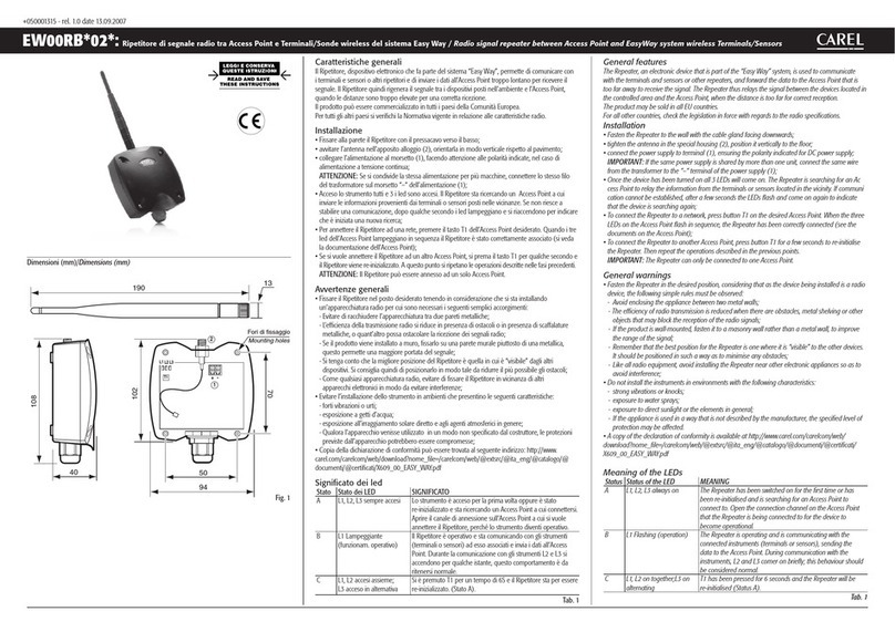
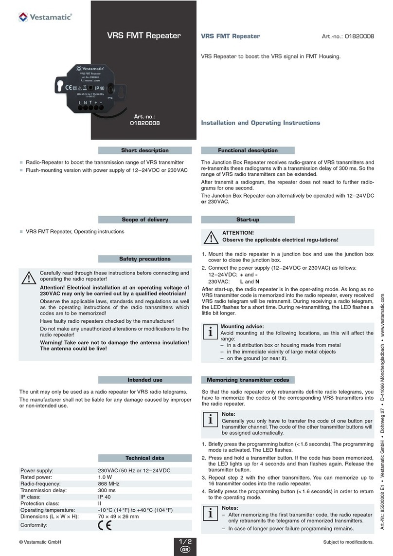
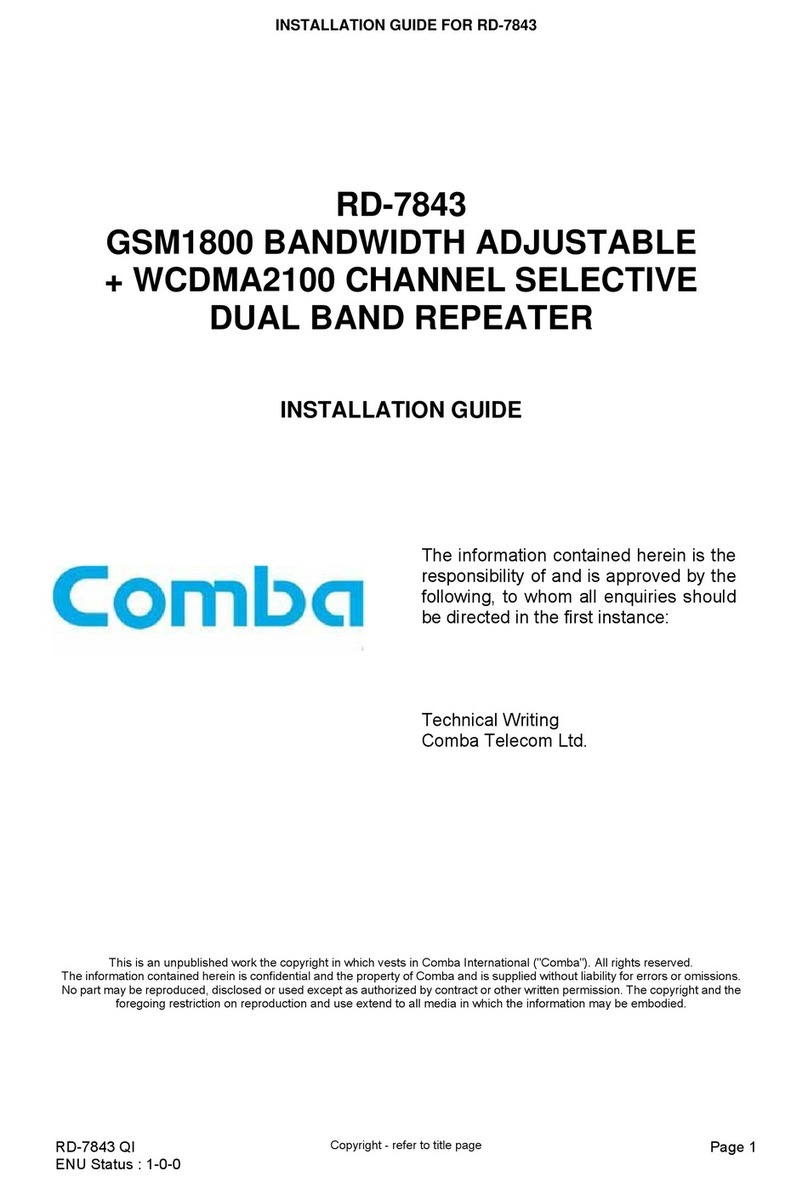
Advanced Wireless Communications AWR-DRP9050 User manual

User Manual
AWR-DRP9050
Digital Radio Repeater

Thank you for purchasing this AWR-DRP9050 DMR Digital and
Analog Repeater by Advanced Wireless Communications (AWC). The
AWR-DRP9050 delivers the latest technology, has the most stable
components, and has the most advanced production technology. The
AWR-DRP9050 will provide you with the reliable performance and high
quality you demand.
This manual should be read to ensure that the user understands the
operation of the AWR-DRP9050. Please read the Safety Instructions
before use.
Thank you!
User Instructions
Please carefully read this manual before attempting to deploy the repeater. The
instructions will explain the various features of this repeater. Please retain these
instructions for future reference.
Safety Instructions
Please observe the following safety instructions to prevent re, accidents,
personal injury, or equipment damage.
• Do not open or modify the repeater in any way to avoid risk of electric shock.
• Do not expose the repeater to rain or moisture to prevent re or electric shock.
• Do not store or use unprotected repeater for prolonged periods in areas of high
dust or excessive moisture.
• Do not the repeater to temperature extremes of either hot or cold.
• Users may experience signal interference if the unit is used near devices such
as televisions or electric generators.
• Do not expose the repeater to long periods of direct sunlight or place near heat
sources.
• Do not place items on top of the repeater. This can obstruct air ow and heat
dissipation during operation.
• Do not install the repeater in explosive environments (inammable gas, dust
particles, metallic powers, grain dust, etc.)
• The radio contains high power components that are not user serviceable or
should be tampered with.
• It is not uncommon for the repeater enclosure to be slightly warm during
operation. This is normal and the repeater may continue to be used.
• The repeater is intended for use as a xed station with the antenna located
outdoors on a rooftop or on an antenna tower. It may be deployed with
distributed antenna systems, but user must have an appropriate engineering
study to ensure that the RF exposure limits are met in transmit.
• Use only the supplied AC cord.

Product Safety and RF Exposure
This equipment is intended for use in occupational / controlled applications
where users have been made aware of the potential for exposure and can
exercise control over their exposure. This radio device is NOT authorized for the
general population, consumer or similar use cases.
BEFORE USING THIS RADIO DEVICE, READ ALL RELATIVE MATERIALS
IN THIS MANUAL FOR IMPORTANT OPERATION INSTRUCTIONS FOR
SAFE USAGE, RF ENERGY AWARENESS, AND CONTROL INFORMATION
FOR COMPLIANCE WITH RF ENERGY EXPOSURE LIMITS IN APPLICABLE
NATIONAL AND INTERNATIONAL STANDARDS.
Federal Communication Commission (FCC) Regulations
The FCC has established limits for safe exposure to radio frequency (RF)
emissions from radio devices. The FCC requires manufacturers to demonstrate
compliance with RF exposure limits before radio devices may be marketed in
the U.S. When two-way radios and repeaters are approved for occupational
/ controlled environment exposure limits, the FCC requires users to be fully
aware of, and exercise control over, their exposure. Awareness and control of
RF exposure can be accomplished using labels, or by education and training
through appropriate means such as information and instructions in user
manuals or safety booklets. Your Advanced Wireless Communications’ two-way
radio or repeater has an RF exposure information label on the device. The
training material below includes useful information about RF exposure and
helpful instructions.
Your Advanced Wireless Communications two-way radio devices are designed
and tested to comply with several national and international standards and
guidelines regarding human exposure to RF electromagnetic energy. In terms of
measuring RF energy for compliance with FCC exposure guidelines, your radio
device radiates measurable RF energy only while transmitting, not when it is
receiving, or in stand-by mode.
WARNING
As the qualied end-user of this radio device you must control the exposure
conditions in the area to ensure the minimum separation distance is maintained
between the antenna and nearby persons for satisfying RF Exposure
compliance. The operation of this transmitter must satisfy the requirements of
Occupational/Controlled Exposure Environment, for work-related use, transmit
only when person(s) are at least the minimum distance from the properly
installed, externally mounted antenna. Transmit only when people outside
the vehicle or away from the repeater antenna are at least the recommended
minimum lateral distance away from the antenna/vehicle.
Maintain a separation distance from the antenna of any person(s) of at
least 180 cm (6-feet).

Advanced Wireless Communications Radio Quality Warranty and Liability
The warranty range and limitation
Advanced Wireless Communications (AWC) is committed to quality and stands
behind its products. AWC will, during the warranty period specied for each
product, repair or replace components that fail as a result of poor workmanship
or materials. This warranty does not cover improper use or intentional damage.
The warranty policy does not include the following conditions:
1. Defects or damages caused by working in abnormal or unusual situations.
2. Defect or damages caused by misuse, accident, or water submersion.
3. Defect or damages caused by unauthorized installation, repair, tampering or
adjustment.
4. Warranty does not extend to cosmetic scratches or damages as a result of
normal use or misuse.
5. This warranty is void if:
(a) The product information label is removed, or if the serial number is tampered
with, changed or cannot be identied.
(b) The repeater enclosure is tampered with or unsealed.
General Items
This warranty policy establishes the liability limits for which AWC is responsible.
AWC has the right to decide, in their sole discretion, whether to repair, replace,
or refund the purchase price of any equipment subject to this warranty. There
are no other options available under this warranty. This express warranty is the
complete agreement. OTHER THAN AS EXPRESSLY SET OUT IN THESE
TERMS OR ADDITIONAL TERMS, NEITHER AWC NOR ITS SUPPLIERS OR
DISTRIBUTORS MAKE ANY SPECIFIC PROMISES ABOUT THE SERVICES
OR PRODUCTS.

CONTENTS
Repeater controls ............................................................................... 1
Indicators........................................................................................ 1
Repeater displays........................................................................... 1
Control keys.................................................................................... 1
Front panel mic connector.............................................................. 2
Rear panels I/O’s............................................................................ 2
Repeater functionality......................................................................... 2
DMR Digital channel....................................................................... 2
Analog channel............................................................................... 2
Hybrid channel................................................................................ 3
Repeater operation............................................................................. 3
Front panel basic operation................................................................ 3
Fault handling guide ........................................................................... 5
Repeater error codes...................................................................... 5

Packing List
The following items are contained in the shipping box. If any item is missing or
damaged, please contact your dealer. Please note that the packing list is for a
complete retail box.
Items Quantity
Repeater 1
AC Power Cord 1
USB Cable (Type-B to Type-A) 1
User Manual Available at www.advancedwireless.com
Warranty Card Available at www.advancedwireless.com
Note: After purchase, please check the items and quantity in the box to ensure
everything is correct.
Repeater Control
Front Panel
Rear Panel

1
Indicators
The front panel includes a row of six status indicators that may be referenced
during repeater operation. When illuminated, they indicate what the current
repeater state is. The following table describes the indicators and their
associated colors.
Repeater Display
The repeater display is a two-digit numeric display with two backlit indicators, A
and B. The repeater display provides the following.
Two-Digit Display
• Selected Channel Number
• Display of current menu option or function related to control key activity
• Error Code Display
Backlit Indicator
• A = DMR Time Slot #1 active when lit
• B = DMR Time Slot #2 active when lit
Control Keys
There are eight keys on the front panel of the repeater that provide various
functions. There are two rows of four keys. They are dened as follows with the
related functions.
receiving

Front Panel Mic Connector
The front panel microphone connect is a standard RJ-45 that may be connected
to a hand microphone or desk microphone. Note that the local microphone only
works in DMR mode. PTT from the local microphone is transmitted as an ALL
CALL on both time slots.
Rear Panel I/O’s
The repeater’s rear panel contains several I/O ports including the cooling fans
and ground lug. They are dened in the following table:
Repeater Functionality
The repeater supports analog, digital and hybrid operation based on
programming. While the repeater may be programmed for multiple channels,
it can only operate on a single channel at a time. The following will describe
channel operation based on programming.
DMR Digital Channel
With a repeater channel programmed for DMR, a frequency pair is programmed
along with the transmit power and RX / TX color code. In addition, a channel
reservation duration is programmed. The channel reservation duration is the
time the repeater channel is held without needing for the subscriber devices to
handshake with the repeater after the initial handshake. During this period, the
repeater will continue to transmit even though there is no signal on the input
until the timer expires.
The repeater when it receives a DMR up-link signal from a device on its RX port
with the correct color code (CC) will repeat the signal on its TX port.
Analog Channel
The repeater may be programmed for analog repeater operation. The repeater
is programmed with the desired analog frequency pair, transmit power, and
encode / decode signaling (CTCSS or DCS). There is no transmit hang time
available in programming.
The repeater when it receives an analog up-link signal from a device on its RX
port with the proper signaling will repeat the signal on its TX port.
2

Repeater Functionality (continued)
Hybrid Channel
The hybrid channel is a special case channel in that it allows the programmed
frequency pair to be shared with both analog and DMR subscriber units. Like
the DMR and Analog channels, the appropriate signaling must be programmed.
Analog devices will use the parameters set for analog operation and DMR
devices will use the parameters set for DMR operation. The digital and analog
devices will not be able to communicate with each other but will be capable of
sharing the channel.
Repeater Operation
1. Main Power On / O – the repeater is powered on and o via the AC power
switch located on the rear panel of the repeater. The front speaker will provide
an audible indication on power on and the two-digit front panel will illuminate.
Note that the repeater goes through a boot-up cycle before it is ready for
operation.
2. Voice / Data Transmit – when the RX port of the repeater receives an uplink
signal from a device, the repeater will retransmit this signal via the TX port if it
meets the required programmed signaling parameters.
3. TX / RX indicators – when the repeater is active, the TX / RX indicators will
illuminate. In DMR, the “A” or “B” will illuminate to indicate which time slot is in
use. The A / B indicators do not illuminate in analog.
4. Key Warning Tone – the eight front panel keys have associated with them
key warning tones. They indicate when a parameter has been changed. A single
beep is used for a valid function and two beeps for error or invalid function.
5. Programming – programming is performed via the rear USB-B connector on
the rear panel of the repeater using a USB-B to USB-A cable.
Front Panel Basic Operation
1. Power-On State – when the repeater is powered on and is idle, the display
will show the current selected channel number.
2. Menu Function – the menu function includes channel switching, monitor
volume, monitor switch (P1), transmit power (P2), password (P3), channel
switching, and volume adjustment. These items are set in the programming
software under “Other Settings.” The operational process is shown below.
If there is no password assigned, press “OK” to bypass password
authentication.
3

4
Front Panel Basic Operation (continued)
3. Password Authentication – if the menu is locked, press “OK” or use the shortcut
function button to enter password authentication. The display will show the following:
• The password is entered using the “F” keys based on the value entered in programming.
The password will be six digits in length. After the password has been entered the “OK”
key is pressed, and the display will show “P1”.
• Press “C” before “OK” will remove the value just entered.
• In any menu setting, Press “C” and the device will activate the password lock state and
go idle.
• If there are no buttons pressed for a minimum of 30 seconds, the repeater will enter the
password lock and idle state.
4. Channel Switching – the channels may be switched using the front panel arrow keys
after the password is entered if enabled. The display will show in the display between 01 to
99 depending on programming. After the arrow keys are used to select the channel, “OK”
is pressed to conrm the channel. “C” is pressed to return to the idle state and display the
current channel.
5. Volume Adjustment – the front speaker volume level is adjusted using the F3 / F4 keys.
The display will show values between U1 to U8 with U1 being the lowest and U8 being the
highest. “OK” is pressed to conrm the selected level. “C” is pressed to activate the level
and return to idle state.
6. Monitor Switch – when the key functions are in the idle state, press “OK” to enter the
monitor switch menu. The display will show “P1.” Press the right arrow key to enter the
menu, and “OK” to enter the monitor switch set-up.
• The arrow keys allow the “ON” or “OF” (o) to be selected.
• Press “OK” to conrm the selected setting. The setting will be saved and active. Pressing
“C” cancels the operation.
• Pressing “C” again navigates back to the P1 menu.
7. Transmit Power - when the key functions are in the idle state, press “OK” to enter the key
menu. Use the arrow key to navigate to the “P2” setting. Press “OK” to enter the transmit
power set-up.
• Press the arrow keys to increase or decrease the transmit power level. The display will
show the current power level and display the new power level setting from L1 to L9. L1 is
equal to 5-Watts and L9 is equal to 45-Watts.
• Press “OK” to conrm and save the new power setting.
• Press “C” to cancel the operation.
8. Password Change – the password may be changed from the key function menu, the “P3”
setting. The arrow keys are used to navigate within the key function menu. You will need to
verify the old password before entering a new password.
• Press “OK” while “P3” is displayed. The display will change to two red dashes ( - - )
• Authenticate the old password per item #3 in this section.
• After the password authentication tone, the new password may be entered.
• Using any combination of the F1 through F4 keys, set a new six-digit password and
press “OK” to conrm and save.
• Repeat the process and when the two entries are identical, the repeater will emit a tone
indicating that the entry process was correct. The display will revert to “P3” indicating the
new password is in eect. If a warning tone is heard, attempt to re-enter the password.
• Press “C” to cancel the operation and press “C” again to return to the idle state.

5
General Guide for Fault Handling
Repeater Error Codes
The repeater will display error codes when a fault occurs. These items are
important to the service technician for troubleshooting and repair. The error
codes are noted in the following table.

6501107©2019 Advanced Wireless Communications. All rights reserved.
(952) 469-5400 / Toll Free: (800) 475-5852
20809 Kensington Blvd
Lakeville, MN 55044-8353
www.AdvancedWireless.com
Table of contents


