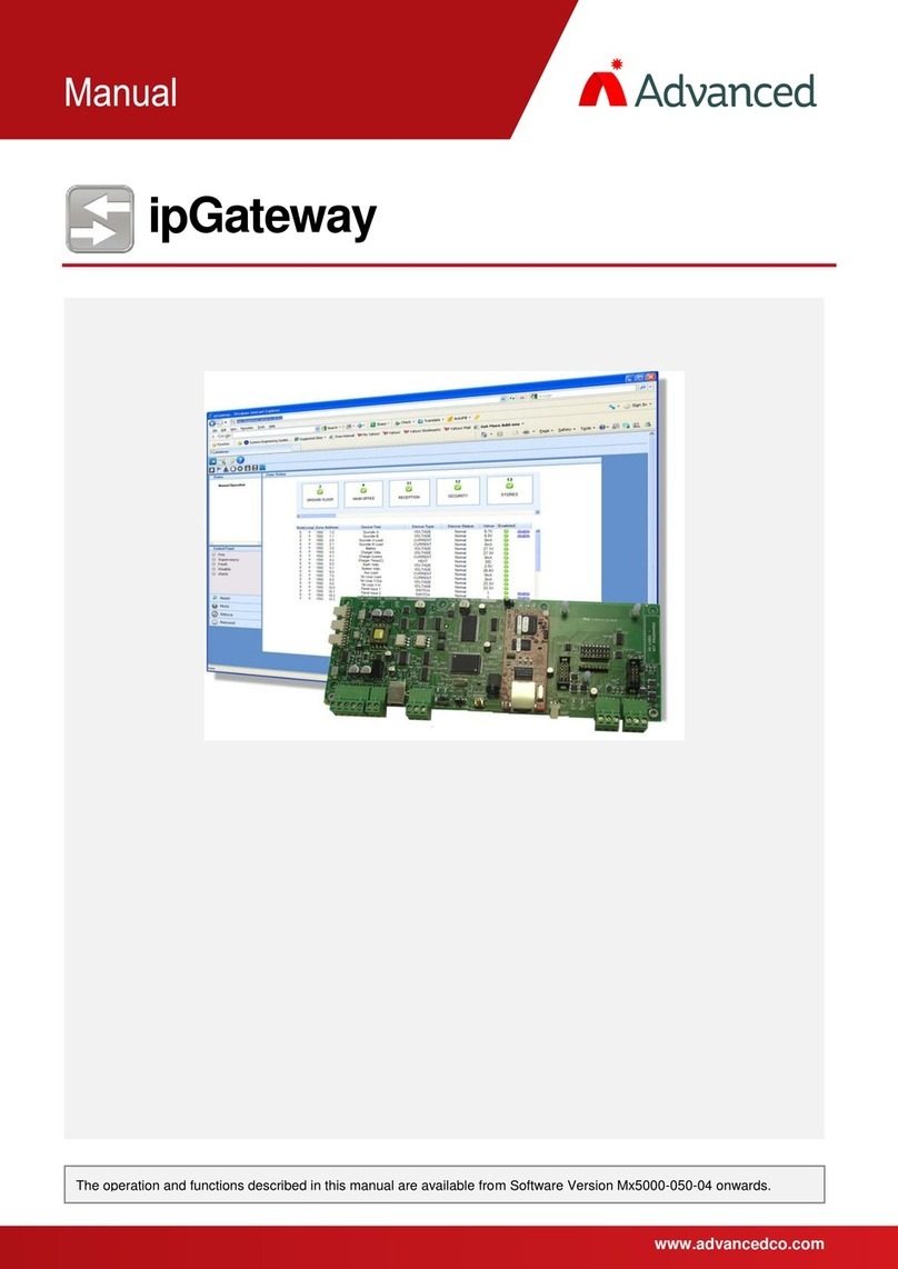
Advanced Axis AX-LAN IpGateway User manual

www.advancedco.com
IpGateway
Figure 1
–
A
X-LAN Wiring

www.advancedco.com
2
Table of Contents Page
1INTRODUCTION / OVERVIEW............................................................................................................................4
1.1PRODUCT DESCRIPTION..................................................................................................................................4
2INSTALLATION....................................................................................................................................................4
2.1MOUNTING THE ENCLOSURE............................................................................................................................4
2.2WIRING ..........................................................................................................................................................5
2.2.1DC Power Input........................................................................................................................................5
2.2.2Fault Input ................................................................................................................................................5
2.2.3Network Connections ...............................................................................................................................5
2.2.4RS232 Serial Interface.............................................................................................................................5
2.2.5Ethernet Port ............................................................................................................................................5
2.3COMMISSIONING THE INTERFACE.....................................................................................................................6
2.3.1Default Settings........................................................................................................................................6
2.4CHANGING AX-LAN NODE INTERFACE SETTINGS.............................................................................................6
2.5NORMAL OPERATION......................................................................................................................................8
3THE SERVER .......................................................................................................................................................8
3.1CONFIGURING THE SERVER .............................................................................................................................8
3.1.1IP Address................................................................................................................................................8
3.1.1.1Network Address Translation (NAT)...............................................................................................................9
3.1.2Subnet Mask ..........................................................................................................................................10
3.1.3Gateway .................................................................................................................................................11
3.1.4SMTP Server Address ...........................................................................................................................11
3.1.5TCP Port Number...................................................................................................................................11
3.1.6Email Address ........................................................................................................................................11
3.1.7SMTP Username....................................................................................................................................11
3.1.8SMTP Password ....................................................................................................................................11
3.1.9Administrator Password .........................................................................................................................11
3.1.10User Password ..................................................................................................................................11
3.1.11Remote Access Level ........................................................................................................................12
3.1.12Consent Timeout ...............................................................................................................................12
4NETWORK SETUP.............................................................................................................................................13
4.1CONFIGURING THE EMAIL SERVER ................................................................................................................13
5THE BROWSER .................................................................................................................................................14
5.1NAVIGATION.................................................................................................................................................14
5.2USERNAME AND PASSWORD .........................................................................................................................14
5.3MAIN FORM..................................................................................................................................................15
5.3.1Anatomy of the Main Form.....................................................................................................................15
5.3.1.1Main Toolbar ................................................................................................................................................15
5.3.1.2Sub Toolbar..................................................................................................................................................16
5.3.1.3Content.........................................................................................................................................................16
5.3.1.4Status Panel .................................................................................................................................................16
5.3.1.5Control Panel................................................................................................................................................16
5.4ZONE STATUS ..............................................................................................................................................16
5.4.1Enable / Disable a Device......................................................................................................................17
5.4.2Enable / Disable a Zone.........................................................................................................................17
5.4.3Filter .......................................................................................................................................................18
5.5EVENTS CONFIGURATION..............................................................................................................................18
5.5.1Email Addresses ....................................................................................................................................18
5.5.2Event Configuration................................................................................................................................19
5.5.3Shifts ......................................................................................................................................................20
5.5.4Text ........................................................................................................................................................20
5.6EVENT LOG..................................................................................................................................................21

www.advancedco.com
www.advancedco.com 3
6PANEL OPERATION .........................................................................................................................................22
7COMMON CONFIGURATION SCENARIOS.....................................................................................................23
7.1PRIVATE INTERNAL ACCESS ACROSS AN EXISTING LAN WHERE NO EMAIL NOTIFICATIONS ARE REQUIRED ........24
7.1.1Configuration elsewhere on the network ...............................................................................................24
7.2PRIVATE INTERNAL ACCESS ACROSS AN EXISTING LAN WHERE INTERNAL EMAIL NOTIFICATIONS ARE REQUIRED
24
7.2.1Configuration elsewhere on the network ...............................................................................................24
7.3PRIVATE INTERNAL ACCESS ACROSS AN EXISTING LAN WHERE EXTERNAL EMAIL NOTIFICATIONS ARE REQUIRED
25
7.3.1Configuration elsewhere on the network ...............................................................................................25
7.3.1.1Email Server ................................................................................................................................................ 25
7.4PUBLIC ACCESS ACROSS THE INTERNET WHERE EXTERNAL EMAIL NOTIFICATIONS ARE NOT REQUIRED.............25
7.4.1Configuration elsewhere on the network ...............................................................................................25
7.4.1.1Router NAT (Port Forward).......................................................................................................................... 25
7.5PUBLIC ACCESS ACROSS THE INTERNET WHERE EXTERNAL EMAIL NOTIFICATIONS ARE REQUIRED....................26
7.5.1Configuration elsewhere on the network ...............................................................................................26
7.5.1.1Router NAT (Port Forward).......................................................................................................................... 26
7.5.1.2Email Server ................................................................................................................................................ 26
7.6PUBLIC ACCESS ACROSS THE INTERNET WHERE AN EXTERNAL EMAIL SERVER IS USED ....................................27
7.6.1Configuration elsewhere on the network ...............................................................................................27
7.6.1.1Router NAT (Port Forward).......................................................................................................................... 27
7.6.1.2Email Server ................................................................................................................................................ 27
8TROUBLESHOOTING .......................................................................................................................................27
8.1WEB PAGE NOT FOUND................................................................................................................................27
8.1.1Private Network......................................................................................................................................27
8.1.1.1IP Address Incorrect .................................................................................................................................... 28
8.1.1.2Subnet Mask Incorrect ................................................................................................................................. 28
8.1.1.3Octal Addressing ......................................................................................................................................... 28
8.1.2Public Network (Internet) .......................................................................................................................28
8.1.2.1Public IP Address Incorrect.......................................................................................................................... 28
8.1.2.2Subnet Mask Incorrect ................................................................................................................................. 28
8.1.2.3Default Gateway Address Incorrect ............................................................................................................. 28
8.1.2.4No NAT Setup.............................................................................................................................................. 28
8.1.2.5Incorrect Port Specified In Browser Address ............................................................................................... 28
8.1.2.6Octal Addressing ......................................................................................................................................... 28
8.2EMAIL NOT SENT..........................................................................................................................................28
8.2.1Incorrect IP Address for SMTP Server ..................................................................................................28
8.2.2User Not Valid on the SMTP Server ......................................................................................................28
8.2.3Incorrect Password ................................................................................................................................29
8.2.4Relaying Not Setup on SMTP Server ....................................................................................................29
9REQUEST FOR INFORMATION........................................................................................................................29
10SPECIFICATIONS..............................................................................................................................................29

www.advancedco.com
4
1 Introduction / Overview
1.1 Product Description
This manual covers the installation and operation of the AX-LAN (ipGateway).
The AX-LAN, ipGateway, connects to an AxisAX Ad-NeT-PluS network providing a gateway to the AxisAX Ad-NeT-
PluS network from any remote location via the internet. By gathering real time information from the AxisAX Ad-NeT-
PluS network, the AX-LAN, ipGateway, gives a visual indication of the state of the network through a standard web
browser with the state of each device being displayed in a clear and concise manner.
Interaction with the AxisAX Ad-NeT-PluS network is also available providing the functionality to enable/disable zones
and/or devices, reset, acknowledge, silence or resound NAC circuits all on the AxisAX Ad-NeT-PluS network (this
feature is only permitted on approval of the Authority Having Jurisdiction).
The AX-LAN can also be configured to react to events on the AxisAX Ad-NeT-PluS network and send event emails
to various preconfigured recipients.
2 Installation
2.1 Mounting the enclosure
The enclosure is provided with three mounting locations (see figure 2). Use appropriate hardware to mount the
enclosure to the wall.
Ensure that there is sufficient space to allow the cover to be removed / opened when the AX-LAN is mounted.
If the cover is completely removed, remember to reconnect the earth ground wire prior to replacing the cover.
8 3/8"
11 5/8"
5 13/16"
1 5/8"
Figure 2 – AX-LAN Enclosure

www.advancedco.com
www.advancedco.com 5
2.2 Wiring
Plug-in terminal blocks are provided for all field wiring connections (see figure 1).
Note: Minimum / Maximum cable size for all connections is 22 – 14 AWG. All electrical wiring should be in
accordance with the National Electric Code and any local requirements.
To minimize the effects of EMC interference all network wiring should be minimum twisted with size suitable for
loading conditions. In areas where wire may come in contact with high frequency interference, such as portable
radio transceivers, etc, the wiring should be twisted shielded. Care should be taken to correctly terminate the shield
to the network in and out terminals.
2.2.1 DC Power Input
The AX-LAN requires connection to a Listed 24 VDC power supply. Connect the 24 VDC power to the “DC Power
Input” terminals.
Note: Use wiring of sufficient size to ensure that the power input voltage is maintained under all supply
conditions – refer to the AX-LAN specifications.
Two terminal inputs/outputs are provided for the 24V DC power input so that, if required, the power can be
continued to other peripheral devices requiring power.
Must be
Grounded
A secure dedicated ground connection is required. Although no system is immune
to the effects of lightning strikes, a secure ground connection will reduce
susceptibility. The use of overhead or outside aerial wiring is not recommended.
2.2.2 Fault Input
The “Fault Input” terminals are normally used to monitor the “normally open” trouble contact of a remote power
supply.
A 10KΩseries resistor should be connected to the relay terminals. If more than one AxisAX module is powered from
the same power supply, it is only necessary to connect the remote power supply trouble monitoring contact to one
of the modules.
If the monitoring of an external power supply is not required, a 10KΩresistor must be placed across the “FAULT
I/P” terminals.
2.2.3 Network Connections
Connect the twisted pair network wiring to the A and B terminals.
Connect the shield to the network SCN terminal.
Note: Special shield (SCN) termination circuits are included
on the AX-LAN module to prevent mains frequency ground
fault loops between network nodes. If shielded cable is
utilized, the shield MUST NOT be connected to any other
ground location.
SCN
B
A
2.2.4 RS232 Serial Interface
The connection to the PC-NeT Field Configuration Tool is via the USB port or serial RS232 terminals.
2.2.5 Ethernet Port
Connect a standard straight through RJ45 Ethernet cable to an existing LAN or router.
Note: Before connecting to an existing LAN, IP addressing information from the building network
administrator (IT department) will be required.

www.advancedco.com
6
2.3 Commissioning the Interface
Each AX-LAN module must have a unique network node address.
2.3.1 Default Settings
The following factory default settings are used, and can be modified as required.
Network Node 50
Next Node 1
Interface Zone 702
RS232 Baud Rate 38400
IP Address 0.0.0.0
Subnet Mask 255.255.255.0
Gateway 0.0.0.0
TCP Port ** 80
SMTP Server 0.0.0.0
Email Address “”
SMTPUser “”
SMTP Password “”
Administrator Password admin
User Password user
Access Level Full Access
Consent Timeout 0 Seconds
** The TCP Port is actually a fixed setting and is presented for information purposes.
Note: If multiple AX-LAN, ipGateway, interfaces or other network nodes with the same default settings are used it is
essential to change the defaults to give unique parameters for each network node.
2.4 Changing AX-LAN node interface settings
AX-LAN node interface default settings can be
modified/changed as required using one of the
following two (2) means of AX-LAN, ipGateway,
communications:
1. AxisAX Virtual Terminal Software
2. PC-NeT Field Configuration Program
Note: In order to communicate with the AX-
LAN, ipGateway, switch SW1 must be
moved to the “Setup” position (i.e. slide to
the left).
NORMAL
SETUP
SW1

www.advancedco.com
www.advancedco.com 7
AxisAX Terminal Software:
To modify/change any settings using the AxisAX Virtual Terminal Software, with the programming switch (SW1) in
the setup position, connect a PC to the RS232 connector and run the AxisAX Terminal Dial Up software (Virtual
Terminal). Select the Menu button and then the “SETUP” area from the virtual terminal.
In the “SETUP” area of the AxisAX Terminal Software, the following items can be either programmed or viewed:
THIS NETWORK NODE: 2
NEXT NETWOK NODE: 1
INTERFACE ZONE: 702
SERVICE NUMBER:
TRACE LOGGING MODE: STANDARD + More>
BMS BAUD RATE: 38400 *
RE-SOUND UPON: NEW DEVICE ALARM
CONFIG DATA: * More>
Note: Items with * cannot be modified
In the “ZONE” area of the AxisAX Terminal Software you are capable of entering “Zone Text” for the specific AX-
LAN, ipGateway. It is recommended that zone text be entered so that any events created by the AX-LAN can be
readily identified at the keyboard displays throughout AxisAX Ad-NeT-PluS network.
PC-NeT Field Configuration Program:
The same modifications/changes that were done with the AxisAX Terminal Software can also be done with the PC-
NeT, Field Configuration Program. In addition, the PC-NeT can also be utilized to configure the server
communications requirements.
Note: Network configuration data can only be entered via the PC-NeT, Field Configuration Program.
To utilize the PC-NeT, Field Configuration Program; connect a PC to the RS232 connector or USB port on the AX-
LAN, ipGateway, and run the PC-NeT Field Configuration Program.
In the Panel Details area of the ipGateway,
define the Ad-NeT-PluS node interface
settings.

www.advancedco.com
8
2.5 Normal Operation
After programming the AX-LAN ensure all programming
connections have been removed and that the
programming switch SW1 has been returned to its
‘Normal” position (i.e. moved to the right).
NORMAL
SETUP
SW1
3 The Server
3.1 Configuring the server
The AX-LAN requires several pieces of
configuration information to allow it to exist
on a network. The PC-NeT, Field
Configuration Program, provides the
necessary fields for entering this
configuration information, this is found in the
“Panel Details” section of the ipGateway
under the heading “TCP/IP Settings”.
Note: Network configuration data can
only be entered via the PC-NeT, Field
Configuration Program.
3.1.1 IP Address
An IP Address is a unique address which allows a device to be identified on a computer network.
IP Addresses essentially come in two forms:
Public / Static IP Address
Private IP Address
A public (or static) IP address allows a device to exist on the internet. Many Internet Service Providers (ISP) offer
packages which include static IP addresses as part of a package.
A private IP address is an address which exists on a private network, i.e. home network or business LAN. An
address is considered private if it falls within one of the following ranges:
10.0.0.0 through 10.255.255.255
169.254.0.0 through 169.254.255.255 (Automatic Private IP Addressing (APIPA) only)
172.16.0.0 through 172.31.255.255
192.168.0.0 through 192.168.255.255
Devices with private IP addresses cannot be accessed directly from the internet. Instead these devices are
accessed through a router via a Network Address Translation (NAT).

www.advancedco.com
www.advancedco.com 9
3.1.1.1 Network Address Translation (NAT)
A Network Address Translation is applied to a Router to allow a device on a private network to be accessed from
the internet. Consider the following network setup:
The NATs are shown in the table below the router.
The three internal devices (Web Server, PC, AX-LAN ipGateway) can now be accessed from the internet. The
following three examples describe how an external user can access these three devices.
Example 1:
To access the Web Server, an external user would type the following into the address bar of their browser
This will direct data to Port 80 (the default HTTP port) on the router with IP address 212.188.225.200. When this
data reaches the router it will be redirected to Port 80 on the device with IP address 10.101.100.21.

www.advancedco.com
10
Example 2:
To access the AX-LAN ipGateway, an external user would type the following into the address bar of their browser
This will direct data to Port 8000 on the router with IP address 212.188.225.200. When this data reaches the router
it will be redirected to Port 80 on the device with IP address 10.101.100.25.
Example 3:
To access the PC, an external user would type the following into the address bar of their browser
This will direct data to Port 9010 on the router with IP address 212.188.225.200. When this data reaches the router
it will be redirected to Port 8000 on the device with IP address 10.101.100.30.
3.1.2 Subnet Mask
The subnet mask is used to identify sub networks from a given IP address.
This allows the possibility to break down a single network into a number of smaller networks.
Possible values for Subnet Mask are
Subnet Mask Available Networks
255.255.255.0 1
255.255.255.128 2
255.255.255.192 4
255.255.255.224 8
255.255.255.240 16
255.255.255.248 32
255.255.255.252 64
255.255.255.254 128
Ask your network administrator for the subnet mask of the network to which you intend to add the AX-LAN
ipGateway.

www.advancedco.com
www.advancedco.com 11
3.1.3 Gateway
The Gateway is the IP Address of the Default Gateway on the local network. This is generally the IP Address of a
router on the network that provides access to the public network (i.e. the internet).
3.1.4 SMTP Server Address
The SMTP Server Address is the IP address of the email server on the local network (i.e. the server which is
hosting Microsoft Exchange). Ask your network administrator for this information.
3.1.5 TCP Port Number
The AX-LAN ipGateway is configured to use port 80 to receive data. This information is presented purely for
information purposes and cannot be changed.
3.1.6 Email Address
This is the email address that will be used in the “From” field of any email sent from the AX-LAN, ipGateway.
3.1.7 SMTP Username
A SMTP (Simple Mail Transfer Protocol) server is the server required to send email.
The SMTP username is used by the SMTP server to check that the user is a legitimate user on the mail server.
3.1.8 SMTP Password
An SMTP password is used by the SMTP server when it is configured to use SMTP Authentication to send email.
The process of SMTP Authentication requires the user to be a valid user on the SMTP server. Each user on the
SMTP server will have a password associated with it. The device wishing to send the email, in this case AX-LAN,
ipGateway, must pass this username along with the valid password to the SMTP server. In general the SMTP
server will use authentication if the “To” address is outside of the SMTP server domain, i.e. an external email
address.
If the username or password is invalid, no email will be sent by the SMTP server.
3.1.9 Administrator Password
When a browser first navigates to the AX-LAN ipGateway, the user will be presented with a logon dialog box
requesting a username and password.
The AX-LAN has two defined users namely, “admin” and “user”.
An administrator is given full read/write access to the AX-LAN, ipGateway, unless consent is required from the Ad-
NeT-PluS administrator (see section 0).
The “user” logon is given read only access.
The administrator password refers to the user “admin”.
3.1.10 User Password
A basic user is given the logon “user” and is allowed read only access to the AX-LAN, ipGateway.
The user password is the password for the basic user logon “user” (see section 3.1.9).

www.advancedco.com
12
3.1.11 Remote Access Level
The Remote Access Level defines the permissions granted to a user accessing the AX-LAN, ipGateway, through a
web browser.
The access levels are defined as:
Level Description
ACCESS READ ONLY Access through the web browser is on a read only basis. The
user cannot change any AX-LAN configuration or affect the Ad-
NeT-PluS network in any way.
ACCESS FULL A user has full read and write access to the AX-LAN, ipGateway.
The user may update AX-LAN configuration and interact with the
Ad-NeT-PluS network. (Requires Authority Having Jurisdiction
Approval)
ALLOW WITH CONSENT The user is given read only access upon logging in to the AX-
LAN, ipGateway. The user must request consent from the owner
of the Ad-NeT-PluS network to gain full access.
Consent is given by enabling remote access from any panel on
the Ad-NeT-PluS network.
The user in question must be an administrator. Consent cannot
be given to a basic user.
3.1.12 Consent Timeout
When the Remote Access Level (see section 0) is set as “ALLOW WITH CONSENT”, this timeout defines the
maximum time, in seconds, for which full access will be granted.
For Example:
If the consent timeout is set to 600, when consent is granted the user will be given full read/write access for
600 seconds (i.e. 10 minutes).

www.advancedco.com
www.advancedco.com 13
4 Network Setup
This diagram shows a basic network setup for
the AX-LAN, ipGateway.
Once the AX-LAN has been configured with
valid network information, i.e. IP Address etc, it
can simply be connected onto the current
private network.
This will allow the AX-LAN to be visible from
anywhere on the private network.
To allow the AX-LAN to be visible from outside
of this private network, i.e. the internet, the
router must be configured with a Network
Address Translation (NAT). A NAT allows the
router to direct requests from the internet to
devices on the private network.
4.1 Configuring the Email Server
To enable the AX-LAN, ipGateway, to send emails outside of the private network, i.e. to external recipients, it may
be necessary to configure the existing email server.
The email server will need to be configured to allow “relaying” through the email server. Most servers will allow an
IP address to be added to a list of devices allowed to relay through the server. The private IP address of the AX-
LAN, ipGateway, must be added to this list.

www.advancedco.com
14
5 The Browser
The information obtained by the AX-LAN is accessible through a standard web browser. At the time of writing AX-
LAN ipGateway is compatible with Internet Explorer 6.0, 7.0, 8.0, 9.0, 10 and Firefox 2.0.
For the remainder of this document Internet Explorer 6 will be used in all examples.
5.1 Navigation
To use a browser to navigate to an AX-LAN, ipGateway, first open the browser and then type the following in the
address bar then press “Go” or hit the “Enter” key:
http://<IP Address>
where:
If accessing the AX-LAN ipGateway remotely
<IP Address> is the IP address of the Router
If accessing the AX-LAN ipGateway on a private network
<IP Address> is the IP Address of the AX-LAN ipGatway (see section 3.1.1)
For example, if the AX-LAN ipGateway has IP address 10.101.100.41, access the AX-LAN ipGateway on a private
network by entering the following http address:
5.2 Username and Password
Before gaining access to the AX-LAN the user
must confirm their identity through a username
and password (see sections 3.1.9 and 3.1.10).
Valid usernames are either “admin” or “user”.
Enter one of these in the “User Name” field.
Enter a valid password for the given user (see
sections 3.1.9 and 3.1.10)

www.advancedco.com
www.advancedco.com 15
5.3 Main Form
Shortly after confirming the username and password the AX-LAN, ipGateway, will display the main form in the
user’s web browser.
5.3.1 Anatomy of the Main Form
The Main Form is broken into five different areas as described below:
5.3.1.1 Main Toolbar
The main toolbar contains three tool buttons which are used to display the three different sections
of the AX-LAN, ipGateway:
Zone Status Displays the list of configured zones in the Ad-NeT-PluS network.
Each zone can be expanded to provide a list of devices contained in
that zone. See section 5.4 for full details.
Events
Configuration Displays the AX-LAN event configuration, i.e. defined email
addresses, email text, event triggers. See section 5.5 for full details.
Event Log Displays the event log from the Ad-NeT-PluS network. See section
5.6 for full details.
Status Panel
Control Panel
Sub Toolbar
Main Toolbar
Content

www.advancedco.com
16
5.3.1.2 Sub Toolbar
The sub toolbar displays a second range of tool buttons applicable to current view.
5.3.1.3 Content
Shows the content associated with the current view.
5.3.1.4 Status Panel
The Status Panel gives a textual representation of the state of the Ad-NeT-PluS network.
5.3.1.5 Control Panel
The Control Panel is split into two sections. The first is an LED representation of the state of the Ad-NeT-PluS
network, similar to that of a typical AX Series intelligent fire alarm control panel.
The second section contains a number of buttons similar to the buttons found on an AxisAX panel. These buttons are
used to perform actions on the Ad-NeT-PluS network:
System Reset
Acknowledges all Panel Buzzers
Silences all Silenceable Outputs
Resounds all Silenced Outputs
5.4 Zone Status
The Zone Status view shows an
overall summary of each zone
on the Ad-NeT-PluS network.
Each zone is represented in the Zone Status Area (content) by a Zone Box (scrolling may be
required to view all Ad-NeT-PluS Network zone boxes). The Zone Box indicates the Zone
Number, user assigned Zone Text and a number of icons which reflect the status of the individual
zone.
Status Icons:
Alarm, Supervisory, Troubles, Warning and Disable
Clicking on a Zone Box will initiate a download of the devices associated with the individual zone:

www.advancedco.com
www.advancedco.com 17
Each device is described in terms of its Node Number, Loop Number, Zone Number, Address, Device User Text,
Device Type, Device Status, Device Answer Back Value and whether the device is enabled.
During the download of the devices associated
with an individual zone, the Zone Box will have
an icon in the upper right hand corner, indicating
download in process. Upon completion of the
download the icon will disappear.
5.4.1 Enable / Disable a Device
A user with full access to the AX-
LAN, ipGateway (see section 0) has
the ability to enable and disable
individual devices using their web
browser.
Clicking on the “disable” link
associated with the individual
device will instruct the AX-LAN,
ipGateway to disable that device on
the Ad-NeT-PluS network.
A device that is currently disabled
will display an “enable” link.
Clicking on this link will instruct the
AX-LAN, ipGateway, to enable the
device on the Ad-NeT-PluS
network.
Note: When a device is disabled on the Ad-NeT-PluS network the device row will change
color to yellow.
5.4.2 Enable / Disable a Zone
Right clicking on a Zone Box allows the user to
enable or disable by zone, rather than by
device.
Note: Zone Enable and Disable buttons are
only available to a user with full access to the
AX-LAN, ipGateway (see section 0).

www.advancedco.com
18
5.4.3 Filter
The AX-LAN provides a number of filters which
can be used to reduce the number of Zone
Boxes being displayed at one time.
In addition to filtering the zones, the filtering
also applies to the devices within the zone. If
the Alarm filter is activated, only zones that are
in Alarm will be displayed. Clicking on one of
the zones that are in Alarm will display a list of
devices within that zone which are currently in
Alarm.
By default all the “Show all zones” filter is
active on AX-LANstart up.
Show zones that are in Alarm
Show zones that are in Supervisory
Show zones that are in Trouble
Show zones that are in Warning
Show zones with Disablements
Show zones with Inputs
Show zones with Outputs
Show all Zones
5.5 Events Configuration
The AX-LAN monitors the Ad-NeT-PluS network for a number of defined system events such as; Alarms,
Supervisory, Troubles, Warnings, Disablements, and Alarm Tests.
When an event occurs, the AX-LAN can be configured to send a notification email to a number of recipients.
The data necessary for defining the events configuration can all be entered using the onboard web browser, this
permits data to be altered from any remote location (with proper password access). It should be noted however, that
this data can only be changed by a user who has full access to the AX-LAN (see section 0).
5.5.1 Email Addresses
Before the AX-LAN can send any notifications, the user must supply the required email addresses. The AX-LAN
can store a maximum of 24 email addresses.
An email address can be added to the AX-LAN by selecting the “Events Configuration” button from the main
toolbar and then selecting the “Email Addresses” button from the sub-toolbar.
Click on the “Add email address” button in the
sub-toolbar. This will display a dialog box
requesting an email address and two zonal
ranges.
The zonal range specifies a validation rule. An
email will only be sent to this recipient if the zone
in which an event occurred falls within one or both
of the defined zonal ranges.
At least one zonal range must be defined. If only
one range is required just leave the “From” and
“To” fields of “Zonal Range 2” blank.

www.advancedco.com
www.advancedco.com 19
To delete a selected email address, select the
address to be deleted by clicking on it and then press
the “Delete selected email address” button in the
sub-toolbar.
If the address is used in the event configuration (see
section 5.5.2) a warning will be displayed.
Pressing “OK” will delete the address from all events.
Pressing “Cancel” will prevent the address from
being deleted and will leave the event configuration
untouched.
5.5.2 Event Configuration
The AX-LAN can be configured to provide email notification of
several system events.
Click on the “Show event configuration” button in the sub-
toolbar.
Each event is broken into eight weekday and eight weekend
shifts (see section 5.5.3 for a description of shifts).
An email notification will only be sent if an event occurs on the
correct day and within the correct shift.
Once an email address is added to the AX-LAN it can be used in
an event notification.
To add an email address, click on the required shift and click
on the “Edit email address in the selected shift” button in
the sub-toolbar.
This will open a dialogue box showing all the defined email
addresses and their associated zonal ranges.
To add an email address, select the check box for that email
address.
To remove an email address un-check the check box.
A maximum of four email addresses may be selected for each
shift.

www.advancedco.com
20
5.5.3 Shifts
The AX-LAN has provision to break a day into a
maximum of eight weekday shifts and eight weekend
shifts. This allows email notifications to be sent to
different people at different times of the day.
Click on the “Show shifts” button in the sub-toolbar.
Defined shifts must be contiguous and run from 00:00 to
00:00, i.e.
Shift 1 = 00:00 to 08:30
Shift 2 = 08:30 to 17:00
Shift 3 = 17:00 to 00:00
Shift times can either be selected from the drop down
list, or can be typed in directly.
To enable a shift, place a tick in the check box.
To disable a shift uncheck the check box.
Once the shifts have been defined as required, the information must be sent to the server using the “Send
update to server” button . When the server has received the update, both the “Send update to server” and
the “Synchronize with server” button will be greyed out.
If, after defining the shifts, the decision is made to return to the shifts already defined on the server, readjust
the times and press the “Synchronize with server” button again.
5.5.4 Text
The text used in the email notifications can
also be configured through the AX-LAN,
ipGateway.
Click on the “Show email event text” button .
There are two text areas displayed on this
page.
The first is the “User Defined Text”. This area
allows four user specific strings to be defined.
The second area is the “Text Layout”. This area defines what text will be included in the body of any email
notification. To add an item of text to the email notification click on the “Add new email text” button . A
new drop down menu will be added to the table. Select the required text type from the drop down list.
Where a “User Text” field is selected, the resulting user text will be displayed in the “User Data” column.
Text rows can be moved up and down the “Text Layout” table using the “Move text up” and “Move text
down” buttons.
When the text layout is defined as required, click on the “Send update to server” button .
If, after defining the text layout, the decision is made to return to the text layout already defined on the
server, click on the “Synchronize with server” button .
Table of contents
Other Advanced Gateway manuals
