NovaTec NMG S20 Guide
______________________________________________________________________________
NovaTec Mobile Gateway S20
NovaTec Mobile Gateway
S20
Mounting and Installation
Version 6.0 from 13.10.2005
- Subject to change without notice -

______________________________________________________________________________
Page 1
Version6.0
______________________________________________________________________________
NovaTec
Mobile Gateway S20
Table of Contents
1.0 Preface .................................................................................................3
2.0 Safety Advice ........................................................................................3
3.0 General Information .............................................................................6
3.1 Product Description ................................................................................6
3.2 Using the Handbook ................................................................................6
3.3 Use of Pictograms ...................................................................................6
4.0 Connection and Mounting ......................................................................7
4.1 Safety Directions for Mounting ................................................................7
4.1.1 Mounting Site .........................................................................................7
4.1.2 Regulations and Master Conditions .........................................................9
4.1.3 Mounting Directions .............................................................................10
4.2 Scope of Delivery ................................................................................11
4.2.1 Opening the Package .............................................................................11
4.2.2 Contents of the Package .........................................................................12
4.3 Mounting ..............................................................................................13
4.4 Laying the Cable....................................................................................13
4.4.1 Strain Relief and Positioning of the Cables ...........................................13
4.5 Internal Structure of NovaTecMobileGatewayS20 ......................................15
4.6 Limitation of the NovaTecMobileGatewayS20 ...........................................20
4.7 NovaTecMobileGatewayS20ConnectorPanel..............................................25
4.8 Earthing the NovaTecMobileGatewayS20 ..................................................26
4.9 Connecting the NovaTecMobileGateway S20.............................................28
4.10 NovaTecMobileGatewayS20TerminalEquipmentInterface................................29
4.10.1 The BRA Interface ................................................................................29
4.10.2 The PRA Interface ................................................................................29
4.10.3 TheAntenna .........................................................................................30
4.10.4 Installinginstructions ofthe outdoorantenna...................................................31
4.11 PinAssignment for Connections to theNovaTecMobileGatewayS20..............33
4.11.1 CCU PinAssignment .............................................................................33
4.11.2 CCU-Light PinAssignment ....................................................................36
4.11.3 CCU-3 PinAssignment ........................................................................36
4.11.4 SOS Pin Assignment .................................................................37
4.11.5 CBS Pin Assignment .................................................................38
4.11.6 WAU front panelAssignment .................................................................39
4.11.7 SXU front panelAssignment ..................................................................41
4.11.8 The Module Sim Card Multiplexer SXU .................................................42
4.11.9 The Sim Card Holder.............................................................................42
4.11.10 SCU front panelAssignment ..................................................................43
4.11.11 The Module Sim Combiner Unit .............................................................44

______________________________________________________________________________
______________________________________________________________________________
NovaTec
Mobile Gateway S20
Page 2
Version6.0
Table of Contents
4.11.12 The Sim Card Holder.............................................................................44
4.11.13 EWU front panelAssignment .............................................................. 45
4.11.14 CAU Pin Assignment .....................................................................49
4.11.15 ULU PinAssignment .............................................................................52
4.11.16 PTI PinAssignment ...............................................................................54
4.11.17 BCU PinAssignment .............................................................................56
4.11.18 SignalAssignment of the Telecommunications Sockets............................57
4.12 ConnectingtheInterfaces.........................................................................................59
4.12.1 Connectionof ISDNTerminalEquipmenttothe BRAInterface.............................59
4.12.2 Star-shaped(Category5) CablingConnection ........................................................61
4.12.3 ConnectingtheTerminalstotheULU......................................................................64
4.12.4 TrunkLineConnectionsto theCCU........................................................................65
5.0 Commissioning.......................................................................................................66
5.1 StatusDisplaysontheNovaTecMobileGatewayS20...............................................66
5.1.1 StatusDisplays onthe CCUand CCU-Light..............................................................66
5.1.2 StatusDisplaysontheCCU-3 ..................................................................................69
5.1.3 StatusDisplays ontheSea-Of-Sims (SOS)..............................................................72
5.1.4 StatusDisplaysontheCall-Back-Server (CBS)......................................................75
5.1.5 StatusDisplays ontheULU ......................................................................................78
5.1.6 StatusDisplays ontheCAU......................................................................................80
5.1.7 StatusDisplays ontheWAU.....................................................................................81
5.1.8 StatusDisplayson theSXU.....................................................................................83
5.1.8.1 Diagnosticsand StatusIndications...........................................................................84
5.1.8.2 DiagnosticsandStatus Indicationsduring thestart-upphase ..................................84
5.1.8.3 Alarmerrormessages duringthestart-up phase .....................................................84
5.1.8.4 StatusIndicationin normaloperation.....................................................................84
5.1.8.5 StatusIndicationduringnormaloperation ...............................................................84
5.1.9 StatusDisplayson theSCU.....................................................................................85
5.1.10 StatusDisplays ontheEWU .....................................................................................87
5.1.11 StatusDisplaysonthePTI ........................................................................................89
5.1.12 StatusDisplays onthe BCU.......................................................................................91
5.2 Features of the Default Configuration ................................................................92
5.3 AlarmContacts ........................................................................................................93
5.4 InstallingtheConfigurationSoftware......................................................................94
5.5 RemarkstoCallback-Configuration ........................................................................97
5.6 RemarkstoSMStoE-Mail Configuration.............................................................103
5.7 Remarks to SIM-Serverinstallation.....................................................................106
6.0 TechnicalData.....................................................................................................107

______________________________________________________________________________
Page3
Version6.0
______________________________________________________________________________
NovaTec
Mobile Gateway S20
1.0 Preface
Dear Customer,
Congratulations on purchasing the NovaTec Mobile Gateway S20. You have selected an
electronic multiplexer and demultiplexer and GSM Gateway that had been developed and
produced using the latest level of technology. We want to thank you for your decision.
The NovaTec Mobile Gateway S20 provides you with an appropriate number of BRA
(S0 interfaces) or GSM interfaces via its PRA interfaces (S2M/E1 interface). This is achieved by
assigning the B-channels of the PRA interface to the BRA or GSM interfaces. The system
operates in either fixed line or switched connection mode and this can be defined through
configuration.
This Mounting and Installation Handbook will enable you to install the NovaTec Mobile Gateway
S20 to suit your technical environment. We would advise you to read this handbook carefully
and to undertake the installation procedure step-by-step according to the instructions.
2.0 Safety Advice
• Do not install the NovaTecMobile Gateway S20 near to heating systems such as radiators
or in the vicinity of electric fields such as, for example, those generated by strip lighting
and engines.
• Do not expose the NovaTecMobile Gateway S20 to dust, damp, vibrations or direct
sunlight.
• Take care that no wires, nails or similar objects can fall through the ventilation slits.
• The NovaTecMobile Gateway S20 cannot be used prior to proper installation.
• Never clean the housing with petrol, thinners or other solvents. Simply wipe it over
with a soft, dry cloth.
• Should internal components of the system become visible following physical
disturbance of the equipment, disconnect the NovaTecMobile Gateway S20 from the
electricity supply immediately.
• The system is equipped with appropirate mains safety plug for use with a 230 volt,
115 volt or 48 volt DC input.This plug should be connected to a mains safety socket
or the dc power terminal.
• The NovaTecMobile Gateway S20 can be operated using eihter a 230/115 volt power
supply or a 48 volt DC power supply. The mains socket allocated to the NovaTecMobile
GatewayS20 should be independent and for the sole use of the NovaTecMobileGateway
S20.
• In order to prevent damage to person or property, never expose the NovaTecMobile
GatewayS20 to rain or other forms of moisture.

______________________________________________________________________________
Page 4
Version6.0
______________________________________________________________________________
NovaTec
Mobile Gateway S20
• For safety reasons, modifications to the construction or security engineering of the NovaTec
Mobile Gateway S20 are forbidden unless express permission has been obtained from
NovaTec Kommunikationstechnik GmbH.
• NovaTec Kommunikationstechnik GmbH will not be held liable for any damage
whatsoever resulting from modifications to the equipment, especially those relating
to repairs to and soldering on the electronic circuit board.
• Mounting and commissioning should only be undertaken by suitably qualified personnel
(e.g. telecommunications technicians or engineers).
• Please follow the safety advice when inserting or replacing the system’s Slide-in
modules.
• The NovaTecMobile Gateway S20 as well as the pole of the outdoor antenna must be
earthed via an earthing cable with a minimum cross-sectional area of 2.5 mm2. Should
installation or operational problems occur which are not covered in this handbook please
contact NovaTec Kommunikationstechnik GmbH immediately.
• To ensure trouble free usage the NovaTecMobileGatewayS20 must be installed according
to this Mounting and Installation Handbook. The NovaTecMobileGateway S20should be
installedinaclosedmetaliccabinet.
• Before commencing installation, ensure that the relevant electricity circuits are voltage
free and properly disabled to avoid them being accidentally switched on whilst you
are working.
• If the equipment is passed on to a third party this Mounting and Installation Handbook
must accompany it.

______________________________________________________________________________
Page5
Version6.0
______________________________________________________________________________
NovaTec
Mobile Gateway S20
Declaration of Conformity:
NovaTec Kommunikationstechnik GmbH. declare under own sole responsibility that the
product NMG-S20 is in conformity with the provisions of the following european council
directive:
1999/5/EC (R&TTE-Directive)
The corresponding declarations and documents are deposited at the manufacturer.
Important Safety Requirements
- Connecting the NMG-S20 to a public telecommunication network, follow the
installation guide.
- Comply with relevant regulations, before radio stations put into operation
- Comply with relevant regulations of local network provider
- The Guideline must be handed over with the equipment
Technologiepark9, 33100 Paderborn, Germany

______________________________________________________________________________
Page 6
Version6.0
______________________________________________________________________________
NovaTec
Mobile Gateway S20
3.0 General Information
3.1 Product Description
The NovaTecMobile Gateway S20 is a processor controlled electronic multiplexer/demultiplexer
and Mobile Gateway. It enables a minimum of 60 B-channels of two PRAinterfaces (S2M/E1
interface) to be assigned to 30 BRA interfaces (S0interfaces) or 60 Mobile channels. The
NovaTecMobile Gateway S20 can be used to undertake switched connection and fixed line
applications simultaneously. The E-DSS1 protocol is observed when the NovaTecMobile
Gateway S20 is utilised for switched connections. An internal switched connection can be
prevented through appropriate configuration.
3.2 Using the Handbook
This handbook is divided into chapters. The order and content of these chapters corresponds
to the correct installation sequence and will lead you through the commissioning process
for the NovaTecMobile Gateway S20. For this reason, we advise you to read the chapters
according to the order in which they are written and to undertake and complete the corresponding
activities as they occur. Only after this you should proceed to the next chapter. If you work in
this manner the mounting and commissioning of the NovaTecMobile Gateway S20 will be easily
and successfully completed.
3.3 Use of Pictograms
Attention:
Vital information which must be followed at all costs otherwise malfunction and
resultant damage can occur.
Note:
Important information which you are advised to follow.

______________________________________________________________________________
Page 7
Version6.0
______________________________________________________________________________
NovaTec
Mobile Gateway S20
4.0 Connection and Mounting
4.1 Safety Directions for Mounting
4.1.1 Mounting Site
• The mounting site should preferably be located within the office or living area close
to where the PC will be located. The NovaTec Gateway S20 can also be installed in the
cellar or attic as well as in other frost-, dust- and heat-free rooms.
• Do not mount your NovaTec Mobile Gateway S20 near to equipment with strong magnetic
fields, for example, large mains transformers, machines or lifts.
• The NovaTec Mobile Gateway S20 is housed in 19“ racks.These racks should be mounted
in an appropriate cabinet or shelf.
• Do not lay the communications or antenna cable parallel to power lines.
• The following regulations and master conditions (see 4.1.2) must be observed at all
times.
• When mounted there should be a minimum ground clearance of 50 mm between the
base of the NovaTec Mobile Gateway S20 cabinet and the ground.
• The NovaTec Mobile Gateway S20 rack should be mounted in a closed cabinet to prevent
contact. Please contact us for consultation.
• The NovaTec Mobile Gateway S20 must be installed in a 19“ housing or a 19“ cabinet.
The system cabinet must been closed all-around to avoid access to any part of the NovaTec
Mobile Gateway S20. The connection and display parts in front of the NovaTec Mobile
Gateway S20 are permitted to be accessed by service Personel only. The front enclosre,
ideally a door, must be locked to avoid unauthorized access.
• The system cabinet must meet the requirements of a fire enclosure in accordance to IEC
950.
• There must be a clearance of 1 HE (44 mm) above and below the NovaTec Mobile
Gateway S20 system rack. If there are racks installed, they are not allowed to cover than
30% of the ventilation opening of the NovaTec Mobile Gateway S20.
• By Installation of the system cabinet you must take care that it cannot be tipped over
or be moved unintentionally.
• Before changing the power supply, the system must be disconnected from the mains
power supply. The power supply is not suitable for hotplug.

______________________________________________________________________________
Page 8
Version6.0
______________________________________________________________________________
NovaTec
Mobile Gateway S20
• After a failure of the NovaTec Mobile Gateway S20 through operation of a protective
device (fuse), the equipment is as still under voltage as long it is connected to the mains
power.
• If more than one NovaTec Mobile Gateway S20 is being installed an a 19“ cabinet, do
not connect more NovaTecMobile Gateway S20 system to mulit socket-outlets than
allowed by the building power supply wiring regulations.

______________________________________________________________________________
Page 9
Version6.0
______________________________________________________________________________
NovaTec
Mobile Gateway S20
Cleaning
The NovaTecMobile Gateway S20 and connected terminal equipment should only be cleaned
with a moistened cloth or an anti-static tissue. Ensure that no liquid enters the system.
Warning note
Your NovaTecMobile Gateway S20 is secured from the trunk line against power surges, for
example lightning. Lines leaving the building must be equipped with coarse protection, for
example, gas discharge elements.
Interference
Should interference occur, please contact your supplier or service technician.
4.1.2 Regulations and Master Conditions
Ventilation
Do not mount your NovaTecMobile GatewayS20 in a narrow non-ventilated cupboard. Rising
heat levels could damage the NovaTecMobileGateway S20.
Dust (DIN 40046 Part 47)
Do not install the NovaTecMobile Gateway S20 in a dusty location, for example, near sanding
machines, circular- or band-saws.
Humidity (IEC 721 3K6)
The NovaTecMobile Gateway S20 must not be exposed to high humidity levels such as those
found, for example, in washrooms, indoor pools, saunas or bathrooms.
Temperature
Your NovaTecMobile Gateway S20 should only be operated in dry rooms where the temperature
remains beween 0° C und 40° C. For this reason, do not install your NovaTecMobile Gateway
S20 in locations subject to direct sunlight or strong cold influences.
______________________________________________________________________________
Page 10
Version6.0
______________________________________________________________________________
NovaTec
Mobile Gateway S20
4.1.3 Mounting Directions
Please observe your general national safety regulations for telecommunications facilities
(VDE 0800 in Germany) and electric power plant and equipment (VDE 0100 in Germany).
Fitting and mounting of electronic equipment must be undertaken by an
appropriately qualified specialist only. Installation and commissioning of
the NovaTec Mobile Gateway S20 must only be undertaken by electronics
personnel who possess the qualifications required by national safety
regulations.
If possible mount your NovaTecMobile Gateway S20 in the immediate vicinity of the mains
electricity supply for the building and a 230V socket.
Do not plug the Novatec Mobile Gateway S20 into the socket until all
installation work has been completed.
Please lay the communications cable to the telephone sockets according to the national
telecommunications cable regulations standards.
You are advised to use the communications cable Type J-Y (St) Y 2x2x0.6
mm for connecting every item of terminal equipment.
To prevent the system against lightning and atmospheric discharge
interferences, the system should be protected with an appropriate
suppressor (please contact NovaTec for more information).

______________________________________________________________________________
Page 11
Version6.0
______________________________________________________________________________
NovaTec
Mobile Gateway S20
4.2 Scope of Delivery
The complete NovaTecMobileGatewayS20system will be delivered in one cabinet in a large
crate. It contains the following components:
4.2.1 Opening the Package
The NovaTecMobile Gateway S20 is packed and delivered in a collapsible cardboard box or
wooden crate. On opening the crate the first item you will see is the cabinet.You will find this
Mounting and Installation Handbook in the cabinet. The 19“ racks and the slide in modules are
already mounted according to your order.
.soP.soP .soP .soP.soP.ytQ.ytQ .ytQ .ytQ.ytQmetImetI metI metImetI
11 sarokcar"91animetsys02SyawetaGeliboMceTavoN tenib
acaniskcar"91foyarrana
21 DCnoitarugifnocdnaecnanetniaM
31 ekil(etoNyrevileDehtnodnifeblliwsnoitisoPlanoitpO .cte,steSgnitnuoM,annetnA
______________________________________________________________________________
Page 12
Version6.0
______________________________________________________________________________
NovaTec
Mobile Gateway S20
4.2.2 Contents of the Package
In case of single unit delivery on opening the package you will find within the cardboard
box. The individual components as listed in Chapter 4.2. In case of cabinet unit delivery
you will find the system inside a wooden box. Please check that the contents of the
cardboard box or wooden box are correct and complete according to the delivery note.
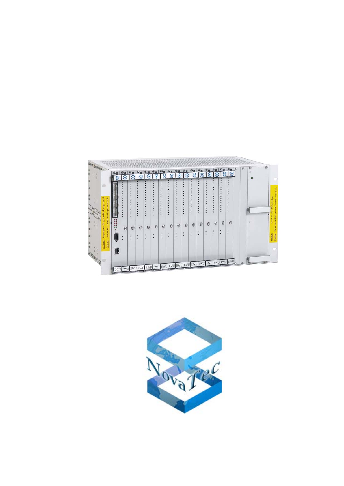
Picture 1:Contents of the package in fullsize configuration
NovaTec Mobile Gateway NMG S20 incl. CD
RF
OUT
RF
OUT
RF
OUT
RF
OUT
RF
OUT
RF
OUT
RF
OUT
RF
OUT
RF
OUT
RF
OUT
RF
OUT
RF
OUT
RF
OUT
RF
OUT
RF
OUT
RF
OUT

______________________________________________________________________________
Page 13
Version6.0
______________________________________________________________________________
NovaTec
Mobile Gateway S20
4.4 Laying the Cabling
All connections except the mains power cable and the earth cable are connected to the NovaTec
Mobile Gateway S20 from the front. The mains power cable is connected from the back using
the cable that has already been fitted for this purpose.All local loops, antennas and extension
lines are connected via special connectors located on the front panels of each of the slide-in
modules. In order to avoid overheating the system, please ensure while laying the cabling that
the air circulation is not obstructed.
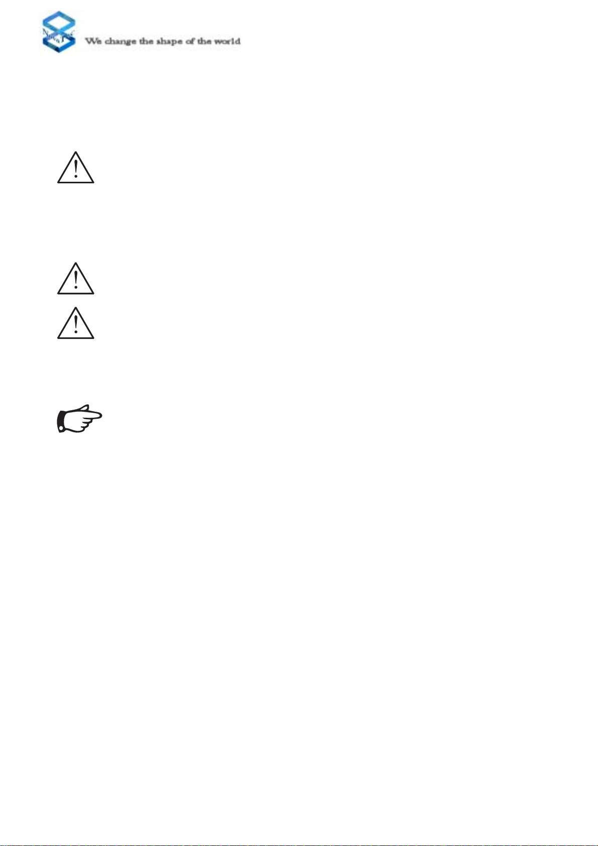
4.4.1 Strain Relief and Positioning of the Cables
All lines that leave the system must be strain relieved at an appropriate place (see illustration in
Picture 2). In the 19“ System the cables are simply of fixed to the frame with a cable binder.You can
therefore use any place on the frame. Each of the wires for the lines for the local loops and the
terminalequipmentinterfaces are colourcoded.The definition ofeachcolour can befoundin Chapter
4.11.
4.3 Mounting
After the NovaTecMobile Gateway S20 has been removed from the box, select the desired
location for mounting the system according to the criteria given in Chapter 4.1.1. TheNovaTec
Mobile Gateway S20 is built in a 19“ rack into which the individual modules are to be inserted.
Both the backplane and the mains power cable are already fitted to this rack. A number of
antenna cables between the WAU and the ACU are installed in accordance to the ordered
configuration (number of mobile channels).
Pleasedecideas earlyaspossible, whetheryouwill connecttheterminal equipment
to the system in a bus structure or a star-shaped (Category 5) cabling format. If
using a star-shaped cabling format, the relevant terminating resistors must be
deactivated (see Chapter 4.11).
Take care that you begin with Pin 32 (Plug 2) when connecting the cabling
to the trunk and terminal equipment interfaces of the CCU.
______________________________________________________________________________
Page 14
Version6.0
______________________________________________________________________________
NovaTec
Mobile Gateway S20
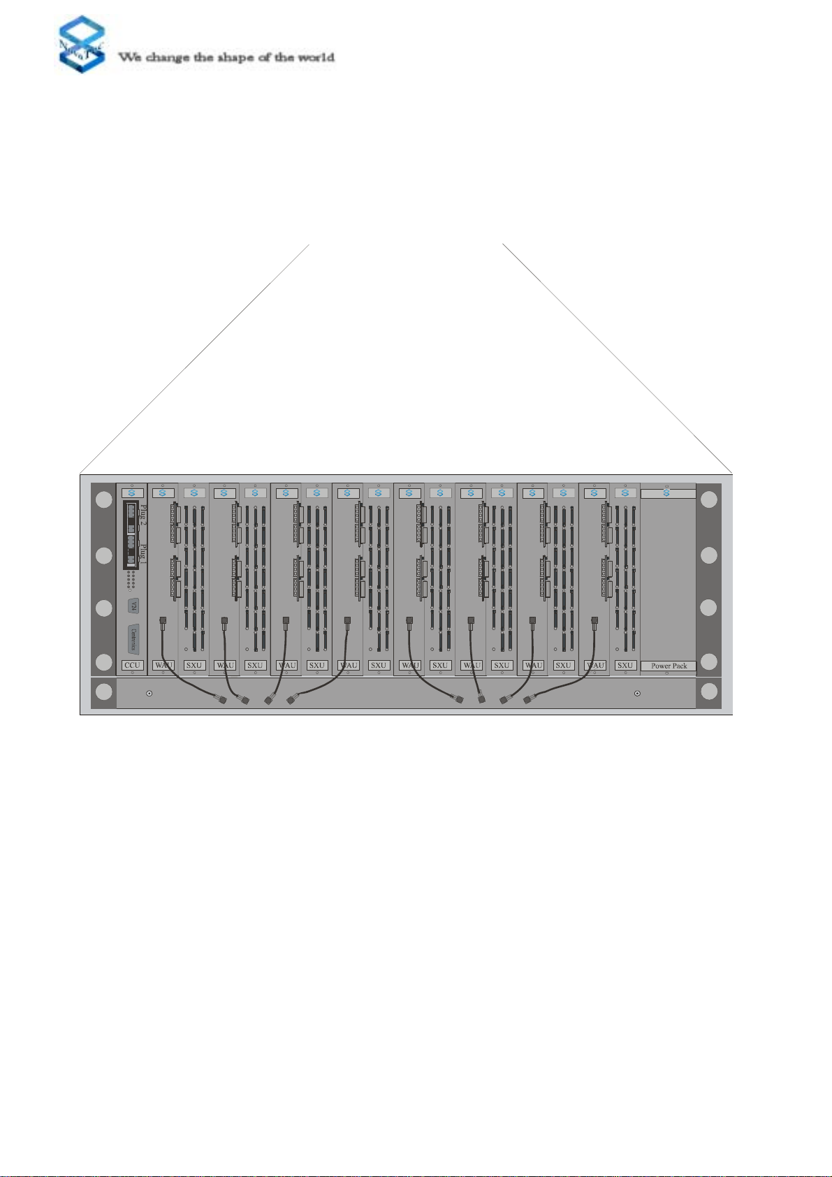
Picture 2: Laying the cabling to the NovaTecMobile Gateway S20
2xPRA 4xBRA
to the outdoor antenna
RF
OUT
RF
OUT
RF
OUT
RF
OUT
RF
OUT
RF
OUT
RF
OUT
RF
OUT
depending from Type of CCU
RF
OUT
1
2
3
4
1
2
3
4
1
2
3
4
1
2
3
4
EWU
RF
OUT
1
2
3
4
1
2
3
4
1
2
3
4
1
2
3
4
EWU
RF
OUT
1
2
3
4
1
2
3
4
1
2
3
4
1
2
3
4
EWU
RF
OUT
1
2
3
4
1
2
3
4
1
2
3
4
1
2
3
4
EWU
RF
OUT
1
2
3
4
1
2
3
4
1
2
3
4
1
2
3
4
EWU
RF
OUT
1
2
3
4
1
2
3
4
1
2
3
4
1
2
3
4
EWU
RF
OUT
1
2
3
4
1
2
3
4
1
2
3
4
1
2
3
4
EWU
RF
OUT
1
2
3
4
1
2
3
4
1
2
3
4
1
2
3
4
EWU
RF
OUT
1
2
3
4
1
2
3
4
1
2
3
4
1
2
3
4
EWU
RF
OUT
1
2
3
4
1
2
3
4
1
2
3
4
1
2
3
4
EWU
RF
OUT
1
2
3
4
1
2
3
4
1
2
3
4
1
2
3
4
EWU
RF
OUT
1
2
3
4
1
2
3
4
1
2
3
4
1
2
3
4
EWU
RF
OUT
1
2
3
4
1
2
3
4
1
2
3
4
1
2
3
4
EWU
RF
OUT
1
2
3
4
1
2
3
4
1
2
3
4
1
2
3
4
EWU
RF
OUT
1
2
3
4
1
2
3
4
1
2
3
4
1
2
3
4
EWU
Ethernet
see CCU3
SCU
3-4
1-1 1-2 1-3 1-4
1-5 2-1
2-2
2-3 2-4 2-5 3-1 3-2 3-3
4-3
4-1 4-2
3-5
4-4
4-5
SCU
3-4
1-1 1-2 1-3 1-4
1-5 2-1
2-2
2-3 2-4 2-5 3-1 3-2 3-3
4-34-1 4-2
3-5
4-4
4-5
SCU
3-4
1-1 1-2 1-3 1-4 1-5 2-1
2-2 2-3
2-4 2-5 3-1 3-2 3-3
4-34-1 4-23-5 4-4 4-5
SCU
3-4
1-1 1-2 1-3 1-4
1-5 2-1
2-2 2-3 2-4 2-5 3-1 3-2 3-3
4-3
4-1 4-23-5 4-4 4-5
SCU
3-4
1-1 1-2 1-3 1-4
1-5 2-1
2-2 2-32-42-53-13-23-3
4-3
4-1
4-2
3-5
4-4
4-5
SCU
3-4
1-1 1-2 1-3 1-4
1-5 2-1
2-2 2-32-42-53-13-23-3
4-34-1 4-2
3-5
4-4
4-5
SCU
3-4
1-1 1-2 1-3 1-4 1-5 2-1
2-2
2-32-4 2-53-13-23-3
4-34-1 4-2
3-5 4-4 4-5
SCU
3-4
1-1 1-2 1-3 1-4 1-5 2-1
2-2
2-32-4 2-53-13-23-3
4-3
4-1 4-23-5 4-4 4-5
SCU
3-4
1-1 1-2 1-3 1-4
1-5 2-1
2-2 2-32-42-53-13-23-3
4-3
4-1 4-2
3-5
4-4
4-5
SCU
3-4
1-1 1-2 1-3 1-4
1-5 2-1
2-2
2-3 2-4 2-5 3-1 3-2 3-3
4-3
4-1 4-23-5 4-4 4-5
SCU
3-4
1-1 1-2 1-3 1-4 1-5 2-1
2-2
2-3 2-4 2-5 3-1 3-2 3-3
4-34-1 4-23-5 4-4 4-5
SCU
3-4
1-1 1-2 1-3 1-4
1-5 2-1
2-2 2-3
2-4
2-5
3-1
3-2 3-3
4-34-1 4-2
3-5 4-4 4-5
SCU
3-4
1-1 1-2 1-3 1-4
1-5 2-1
2-2 2-3
2-4
2-5
3-1
3-2 3-3
4-3
4-1 4-23-5 4-4 4-5
SCU
3-4
1-1 1-2 1-3 1-4
1-5 2-1
2-2
2-32-42-53-13-23-3
4-3
4-1 4-2
3-5
4-4
4-5
SCU
3-4
1-1 1-2 1-3 1-4
1-5 2-1
2-2 2-3 2-4 2-5 3-1 3-2 3-3
4-3
4-1 4-2
3-5
4-4
4-5
Ethernet

______________________________________________________________________________
Page 15
Version6.0
______________________________________________________________________________
NovaTec
Mobile Gateway S20
4.5 Internal Structure of the NovaTec
Mobile
Gateway S20
The NovaTecMobile Gateway S20 is comprised of several different modules.All modules can
be inserted into the 19“ rack and then connected together at the rear of the rack via the
backplane. The individual slots inside the system are clearly numbered on the backplane to
ensure easy identification. The left slot is Slot 1 where only the CCU should be inserted. On the
right, next to the CCU is Slot 2, and so on up to Slot 17. On the right-hand side of Slot 17 is
the power supply slot. This slot is double the width of the others and accommodates the power
supply for the whole rack. The slot designations (slot numbers) can be found on the front side
of the back plane. The numbers can be seen on the back plane when viewed from the insertion
side of the 19“ rack.
The CCU is a Central Control Unit and is the core of the system. The CCU provides four
BRA interfaces, one Centronics and one RS232 interface. In addition the CCU provides a
plug in space for either a four time BRA or a two time PRA expansion board.
The CCU Light corresponds to the CCU with the exception that the CCU Light has no BRI
Interfaces.
The CCU-3 corresponds in the basic functions to the CCU. The difference is firstly that
the CCU-3 has instead of the printer interface an ethernet interface, which can be either
operated with 10MBit or 100Mbit. Also the CCU-3 does not have ISDN Interfaces on the
board but can be equipped with either 2 PRI or 2 BRI boards. All Support-Functions, that
are on the CCU-Light/CCU via V.24 or ISDN are still realisable and can be carried out via
Ethernet on the CCU-3.
The Call-Back-Server (CBS) corresponds in the optical features the same as the CCU-3.
When the system is being used with the Call-Back-Functionality, the corresponding required
software CBS must be used. Installation guides for the CBS can be found in Chapter 5 of
this handbook under CBS.
The Sea-Of-Sims (SOS) must be used in conjunction with the Sim-Server . The SOS
corresponds in the optical features the same as the CCU 3. Operation of the NMG as Sim-
Server requires the installation of the SOS software and one SCU must be installed in the
system. Installation guides for the SOS can be found in Chapter 5 of this handbook under
SOS.
The WirelessAccess Unit (WAU) provides the access to the mobile network and contains:
- up to two daugther boards with two dual band engines each
- one 4 to 1 antenna combiner/multiplexer
- the electronic access to the backplane (hot plugable)
Please note: Never run the system without antenna! Do not leave any RF input without
termination!
Each daughter board contains the SIM card reader, which is accessible via the front panel.

______________________________________________________________________________
Page 16
Version6.0
______________________________________________________________________________
NovaTec
Mobile Gateway S20
The CAU (if installed) is a Carrier Unit. This module offers three plug in spaces for
expansion boards. Both BRA or PRA or a combination of both types of expansion boards
can be inserted.
Usually the BRA interfaces are not provided with 42 Volts ISDN line power. If you want
to connect a BRA interface to an item of terminal equipment that also needs a power
supply from the BRA interface, it will be necessary to use a DC4. The DC4 is a seperate
slide in module, that will provide the necessary voltage to power terminal equipment
connected to the BRA interface. This module is simply added to the existing modules by
inserting it into a slot in the rack.
TheAntenna Combiner Unit (ACU) gathers the output of the WAU cards to one RF output.
This RF output shall be connected to the nextACU input or directly to the outdoor antenna
(the number of the possible cascade stages is location pendant. For more information please
contact NovaTec). TheACU contains 4, 8 or16 inputs. 15 inputs shall be connected to the
RF outputs of the WAU’s (in a 60 channel configuration) or should be terminated by RF
termination resistors (please consolt NovaTec).
Please note: Never run the system without antenna! Do not leave any RF input without
termination!
The SXU is an additional module which is used in conjunction with the WAU. In this
combination the SXU allows the number of Simcards per channel available to the WAU
according to configuration parameters to be chosen between 1 and 5 Simcards per channel.
The Sim-Combiner-Unit (SCU) corresponds optically to the SXU. The Status Displays of
the SCU are different than those on the SXU and are therefore alsoseparately described. The
SCU is only for operation with the NMG as a Simserver, and therefore requires the SOS
software to be installed for this to be used.
The EWU contains four GSM mobile engines and four SIM card readers for each GSM-
Channels. The front panel contains:
- One RF output to be connected to the ACU or to an appropriate antenna.
- One strain relief lug for the antenna cable.
The EWU contain four LEDs for each mobile engine and two LEDs for the EWU itself as
Status-Display. The SIM card reader GSM-Channel can be inserted by SIM cards of diffe-
rent providers (multiple provider mode) at the same time or can be left without SIM card.
Standard or prepaid SIM cards can be handled by the system at the same time.
The ULU is a Module that can supply 4 X U-Interfaces. On these interfaces endequipments
with U-Interfaces can be connected. In combination with PT-Repeaters and PT-US it is
then possible to operate end equipments with BRI Interfaces up to 24km away from the
actual system.
The ULU is also available with powered interfaces therefore end equipments i.e. the PT
can be powered over greater distances.

______________________________________________________________________________
Page 17
Version6.0
______________________________________________________________________________
NovaTec
Mobile Gateway S20
The PTI is a Module that can convert a BRI Interface to a U Interface. This would for
example be required when a row of ISDN end equipments in a Star formation are terminated
to a single point.
The following could be one solution: The PTI-SU in combination with the PT-US would
be operated, If at the location no power supply socket was available the use of the PTI-
SU-LP and the PT-US-LP would enable the power supply to be available to the equipment
at greater distances.
The DC4 is a power supply module. When Bri Interfaces are required for example for the
use of ISDN telephones and these ISDN telephones require power supply over the BRI
interface then a DC4 must be used within the system. For calculation purposes 8 X ISDN
telephones with typically 2 watts each require the use of 1 X DC4.
The B-Channel-Unit (BCU) enables the connection of the system to one or more IP Network
for using VOIP-Applications. This then gives the possibility to re-route Data or Speech
that is received into the system via ISDN, GSM or IP to other already existing IP networks.
The BCU is available as either a 4 Channel, 8 channel, 16 channel or 32 channel BCU. The
Modules are not destinguishable from each other from a front. If the BCU is removed from
the System a sticker can be found on the connectors on the Backplane with the Model
number, hereby the individual variants of the BCU can be differentiated. Each BCU can be
populared with a GPS receiver doughter board. This doughterboard is optional necessary
to be used minimum one in a system, when the NovaTec S20 has no other Synchronisation
Source and synchron data should be transfered via IP network (TDM over IP).
The Plug-in cards are sub Modules that can be attached to various mainboard Modules.
The Modules that can be equipped with Plug-in cards are the CCU, CCU-3 and CAU.
The following Plug-in cards are available at this time:
BRI-Plug-in card
The BRI-Plug-in card makes 4 additional BRAinterfaces available.With the BRAPlug-in
cards there are two different variants .The BRI Plug-in card with the article number
1F5021-2 only allows ISDN terminals to be attached. To the BRI Plug-in card with the
article number 1F5020-2 ISDN terminals or ISDN local loops can be attached alternatively.
The function of the proposed interface must be defined in the configuration.
PRI-Plug-in card
The PRI Plug-in card is likewise in two different variants available:
The PRI Plug-in card with the article number 1F5020-1 makes two S2M-Interfaces
available. On the other hand the PRI Plug-in card with the article number 1F5020-1/1
makes available only one S2M-Interface.
PRI-Plug-in card (with optional Echo Cancelation)
The PRI (ISDN 30) Module is available in 6 Variants:
By way of the Article number on the delivery notice can be seen which module is
actually installed in the system.
The 6 variants are:
1F5100 -> S2M-Add-on board with 2 PRI (ISDN 30) Interfaces
1F5100/1 -> S2M-Add-on board with 1 PRI (ISDN 30) Interface
1F5100/1E -> S2M-Add-on board with 1 PRI (ISDN 30) Interface on which
echocancelling is active.

______________________________________________________________________________
Page 18
Version6.0
______________________________________________________________________________
NovaTec
Mobile Gateway S20
1F5100E -> S2M-Add-on board with 2 PRI (ISDN 30) Interfaces with echocancelling
active on Interface 2
1F5100ER -> S2M-Add-on board with 2 PRI (ISDN 30) Interfaces with echocancelling
active on Interface 2 and switch through for the 2nd S2M interface to the 1st when system
is inactive.
These S2M (PRI ISDN 30) Add-on boards can be installed on the CCU3, CCU_Light and
the CAU.
1F5100R -> S2M-Add-on board with 2 PRI (ISDN 30) Interfaces with switch through for
the 1st S2M interface to the 2nd when system is inactive.
The Add-on board with the numbers 1F5100, 1F5100/1 and 1F5100R have no
echocancelling functions.
The Add-on board with the numbers 1F5100/1E 1F5100E and 1F5100R have
echocancelling functions on channel 1 (Recognisable by an „E“ in theArticle number).
TheAdd-on board with the numbers 1F5100ER and 1F5100R switch between Interface 1
to Interface 2 when the system is inactive, this allows for operated systems behind the
NovaTec to carry on operating when the NovaTec is out of operation.
GSM-2 Plug-in-card
The GSM-2-plug in card can be used on the WAU. It supports the system with two GSM-
Dual-Band interfaced with DTMF.
GPS-Receiver
The GPS-Receiver is an plug-in card only for the BCU. it supports the system with an
reference clock if no other reference clock source is available. In this case the system
needs minimum one receiver on one BCU.
SIM-Reader Plug-in card
The SIM-Reader Plugin-in card is an Sub-Modul only for the EWU. It supplies the EWU
with 16 Sim-Card-Reader ( 4 for each GSM-Channel of the EWU) and will be needed, for
lokal SIM-Cards. For Applications with SIMs in SIM-Server only the SIM-Reader Plug-
in card is not neccessary.

______________________________________________________________________________
Page 19
Version6.0
______________________________________________________________________________
NovaTec
Mobile Gateway S20
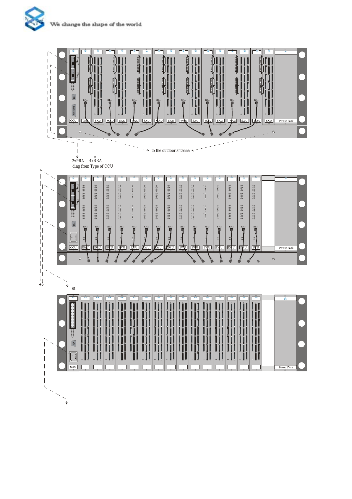
Picture 3: Internal Structure of the NovaTecMobileGatewayS20
RF
OUT
RF
OUT
RF
OUT
RF
OUT
RF
OUT
RF
OUT
RF
OUT
RF
OUT
RF
OUT
RF
OUT
RF
OUT
RF
OUT
RF
OUT
RF
OUT
RF
OUT
Terminaton
Resistor
to Antenna one to Antenna tw
o
NMG-S20, 60 Channel without SXU.
RF
OUT
RF
OUT
RF
OUT
RF
OUT
RF
OUT
RF
OUT
RF
OUT
RF
OUT
to Antenna one to Antenna two
NMG-S20, 32 Channel with SXU.
Antenna Combiner Unit
Antenna Combiner Unit
Table of contents
Other NovaTec Gateway manuals


