Advanced Mxp-554 User manual

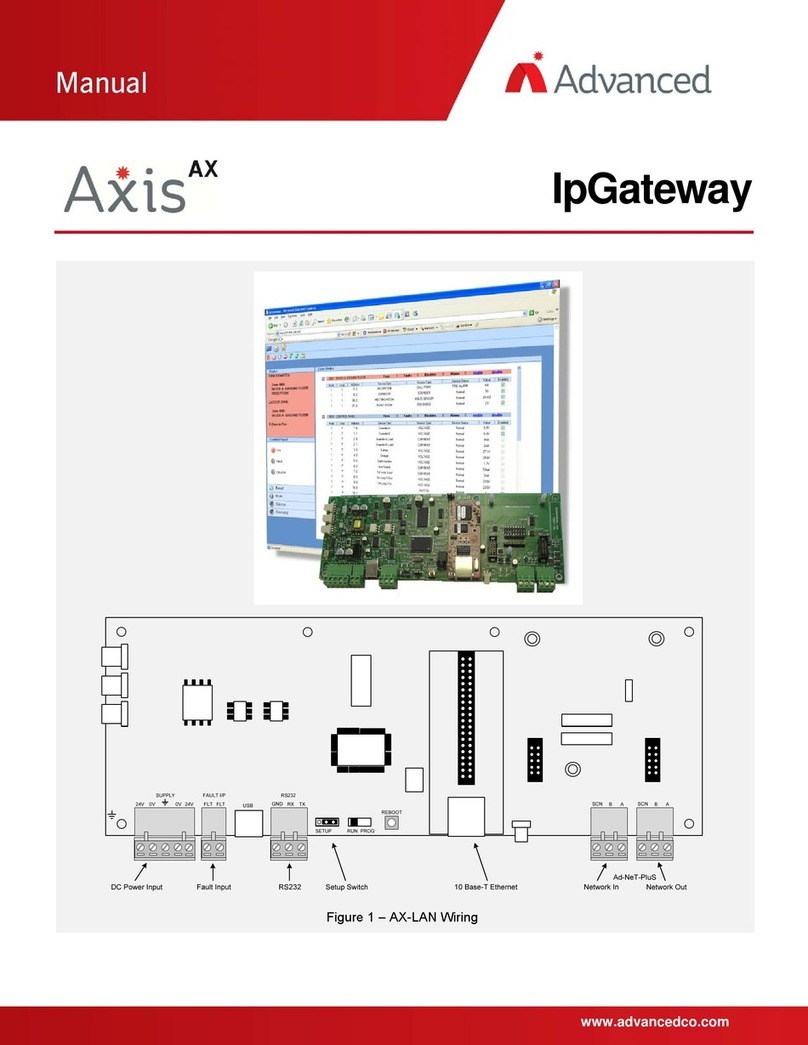
www.advancedco.com
ipGateway
The operation and functions described in this manual are available from Software Version Mx5000-050-04 onwards.

www.advancedco.com
Specifications:
Models, Sales Order Parts:
Mxp-554 ipGateway LAN Interface –Card Only (/FT = Fault Tolerant network)
Mxp-554-BX ipGateway LAN Interface –Boxed (/FT = Fault Tolerant network)
Applications / Limitations:
Provides remote access to devices on an Ad Net network.
Configurable event email notification.
Maximum of 2 simultaneous users.
Minimum Screen Resolution 1024 x 768
Compatibility:
Mx-5000 Series Fire Alarm Panels
Mx-4000 Series Fire Alarm Panels
Compatible with Internet Explorer 6,7 & 8, and Firefox 2 & 3
Use the standard model on standard networks.
Use the fault tolerant model on fault tolerant networks.
Item
Specification Details
Applicable Standards
EN54-18
Operating Temperature
-5°C to 40°C
Relative Humidity
95% Non Condensing (maximum)
PCB
38.5mm (H) x 245mm (W) x 90mm (L)
Supply
24V (18V to 28V) DC
Supply Current
70mA (/FT: 110mA) at 24V DC
LAN Interface
10Base-T, RJ45
Serial Interface
Isolated RS232 Interface
Fault Input
Monitor Input for Power Supply Fault Output
Indications
On-board LED indicators for HEARTBEAT, NETWORK transmit /
receive, RS232 transmit / receive, LAN ACTIVITY, LAN
CONNECTIVITY, LAN RUN
Enclosure
IP30: Dimensions 218mm (H) x 300mm (W) x 45mm (D) RAL7035
Weight
2 kg
Knockouts
4 Top, 1 Bottom, 4 Bottom Rear
Approvals
G210022
As our policy is one of constant product improvement the right is therefore reserved to modify product specifications without prior notice

www.advancedco.com
3
Table of Contents Page
1INTRODUCTION.............................................................................................................................................5
1.1 MOUNTING ...............................................................................................................................................5
1.2 WIRING....................................................................................................................................................5
1.1 DC POWER SUPPLY .................................................................................................................................6
1.2 FAULT INPUT............................................................................................................................................6
1.3 NETWORK CONNECTIONS .........................................................................................................................6
1.4 RS232 SERIAL INTERFACE.......................................................................................................................7
1.5 10 BASE-T ETHERNET PORT.....................................................................................................................7
1.6 COMMISSIONING THE INTERFACE...............................................................................................................7
1.7 DEFAULT SETTINGS..................................................................................................................................7
1.8 CHANGING THE INTERFACE SETTINGS........................................................................................................8
1.9 NORMAL OPERATION................................................................................................................................8
2THE SERVER .................................................................................................................................................8
2.1 CONFIGURING THE SERVER .......................................................................................................................8
2.1.1 IP Address..........................................................................................................................................9
2.1.1.1 Network Address Translation (NAT) ........................................................................................................9
2.1.2 Subnet Mask....................................................................................................................................11
2.1.3 Gateway...........................................................................................................................................11
2.1.4 SMTP Server Address .....................................................................................................................11
2.1.5 TCP Port Number ............................................................................................................................11
2.1.6 Email Address..................................................................................................................................11
2.1.7 SMTP Username .............................................................................................................................11
2.1.8 SMTP Password ..............................................................................................................................11
2.1.9 Administrator Password...................................................................................................................12
2.1.10 User Password ............................................................................................................................12
2.1.11 Remote Access Level..................................................................................................................12
2.1.12 Consent Timeout .........................................................................................................................12
3NETWORK SETUP ......................................................................................................................................13
3.1 CONFIGURING THE EMAIL SERVER ..........................................................................................................13
4THE BROWSER...........................................................................................................................................14
4.1 NAVIGATION...........................................................................................................................................14
4.2 USERNAME AND PASSWORD...................................................................................................................14
4.3 MAIN FORM............................................................................................................................................15
4.3.1 Anatomy of the Main Form...............................................................................................................15
4.3.1.1 Main Toolbar...............................................................................................................................................15
4.3.1.2 Sub Toolbar...........................................................................................................................................15
4.3.1.3 Content..................................................................................................................................................15
4.3.1.4 Status Panel ..........................................................................................................................................16
4.3.1.5 Control Panel.........................................................................................................................................16
4.4 ZONE STATUS ........................................................................................................................................16
4.4.1 Enable / Disable a Device................................................................................................................17
4.4.2 Enable / Disable a Zone...................................................................................................................17
4.4.3 Filter.................................................................................................................................................17
4.5 EVENTS CONFIGURATION........................................................................................................................18
4.5.1 Email Addresses..............................................................................................................................18
4.5.2 Event Configuration .........................................................................................................................19
4.5.3 Shifts................................................................................................................................................19
4.5.4 Text..................................................................................................................................................20
4.6 EVENT LOG............................................................................................................................................20
5PANEL OPERATION ...................................................................................................................................21
6COMMON CONFIGURATION SCENARIOS ...............................................................................................22
6.1 PRIVATE INTERNAL ACCESS ACROSS AN EXISTING LAN WHERE NO EMAIL NOTIFICATIONS ARE REQUIRED ..23
6.1.1 Configuration elsewhere on the network .........................................................................................23
6.2 PRIVATE INTERNAL ACCESS ACROSS AN EXISTING LAN WHERE INTERNAL EMAIL NOTIFICATIONS ARE
REQUIRED ...........................................................................................................................................................23
6.2.1 Configuration elsewhere on the network .........................................................................................23

www.advancedco.com
4
6.3 PRIVATE INTERNAL ACCESS ACROSS AN EXISTING LAN WHERE EXTERNAL EMAIL NOTIFICATIONS ARE
REQUIRED .......................................................................................................................................................... 24
6.3.1 Configuration elsewhere on the network ........................................................................................ 24
6.3.1.1 Email Server..........................................................................................................................................24
6.4 PUBLIC ACCESS ACROSS THE INTERNET WHERE EXTERNAL EMAIL NOTIFICATIONS ARE NOT REQUIRED ...... 24
6.4.1 Configuration elsewhere on the network ........................................................................................ 24
6.4.1.1 Router NAT (Port Forward) ...................................................................................................................24
6.5 PUBLIC ACCESS ACROSS THE INTERNET WHERE EXTERNAL EMAIL NOTIFICATIONS ARE REQUIRED............. 25
6.5.1 Configuration elsewhere on the network ........................................................................................ 25
6.5.1.1 Router NAT (Port Forward) ...................................................................................................................25
6.5.1.2 Email Server..........................................................................................................................................25
6.6 PUBLIC ACCESS ACROSS THE INTERNET WHERE AN EXTERNAL EMAIL SERVER IS USED ............................. 26
6.6.1 Configuration elsewhere on the network ........................................................................................ 26
6.6.1.1 Router NAT (Port Forward) ...................................................................................................................26
6.6.1.2 Email Server..........................................................................................................................................26
7TROUBLESHOOTING................................................................................................................................. 27
7.1 WEB PAGE NOT FOUND......................................................................................................................... 27
7.1.1 Private Network............................................................................................................................... 27
7.1.1.1 IP Address Incorrect..............................................................................................................................27
7.1.1.2 Subnet Mask Incorrect...........................................................................................................................27
7.1.1.3 Octal Addressing...................................................................................................................................27
7.1.2 Public Network (Internet) ................................................................................................................ 27
7.1.2.1 Public IP Address Incorrect...................................................................................................................27
7.1.2.2 Subnet Mask Incorrect...........................................................................................................................27
7.1.2.3 Default Gateway Address Incorrect.......................................................................................................27
7.1.2.4 No NAT Setup.......................................................................................................................................27
7.1.2.5 NAT Setup Incorrectly ...........................................................................................................................27
7.1.2.6 Incorrect Port Specified In Browser Address.........................................................................................27
7.1.2.7 Octal Addressing...................................................................................................................................27
7.2 EMAIL NOT SENT................................................................................................................................... 28
7.2.1 Incorrect IP Address for SMTP Server............................................................................................ 28
7.2.2 User Not Valid on the SMTP Server............................................................................................... 28
7.2.3 Incorrect Password ......................................................................................................................... 28
7.2.4 Relaying Not Setup on SMTP Server ............................................................................................. 28
8REQUEST FOR INFORMATION................................................................................................................. 28

www.advancedco.com
5
1 Introduction
The ipGateway connects to an existing Ad-Net fire network, providing a gateway to the local fire network from
any remote location via the internet.
By gathering real time information from the fire network it gives a visual indication of the state of the fire network
through a standard web browser.
The state of each device on the network is displayed in a clear and concise manner.
Interaction with the fire network is also available, providing the functionality to enable/disable zones,
enable/disable devices, reset the network, mute the network, silence or resound sounders on the network.
The ipGateway can also be configured to react to events on the network by sending emails to configured
recipients.
The ipGateway is supplied as either a card only (for installation in an Mx-5000 rack utility enclosure or other
suitable enclosure) or as a boxed version.
1.1 Mounting
The boxed version enclosure is provided with
three (6mm diameter) fixing points. Refer to the
diagram opposite for dimensions. Use
appropriate fixings to mount the enclosure on
the wall.
Ensure that there is sufficient space to allow
the cover to be removed / opened when the
panel is finally mounted.
If the cover is completely removed, remember
to reconnect the earth lead prior to re-
assembly.
113 mm
170 mm
113 mm
296 mm
213 mm
The card should be mounted in an earthed
enclosure.
Use the supplied M3x10 Brass Pillars and
screws (x5) and mount using fixing holes
marked ‘A’ in the diagram opposite.
1.2 Wiring
The unit is designed for easy wiring installation.
“Plug-in” terminal blocks are provided for all
connections to the unit.
The diagram below shows the positions for all
connections to the unit.
N.B: Minimum / Maximum cable size for all
connections is limited to 0.5mm² / 2.5mm² (22-
14AWG).
All electrical wiring installation work should be
carried out in accordance with the code of
practice applicable in the country of installation.
To maintain electrical integrity of the SELV
wiring on the DC Power and Communications
lines all SELV wiring should be segregated
from LV mains wiring and be wired using cable
with insulation suitable for the application.
To minimise the effects of EMC interference all
data wiring circuits should be wired with a
twisted pair of conductors with a cross sectional
area suitable for the loading conditions.
In areas where cabling may come into contact
with high frequency interference, such as
portable radio transceivers etc, the data wiring
cable should be of a twisted pair construction
within an overall screen. Care should be taken
to correctly terminate this screen, refer to the
information below.
A
A
A
A
A

www.advancedco.com
6
1.1 DC Power Supply
The MXP554 requires a 24V power supply.
Connect the 24V DC supply feed to the
SUPPLY + 24V and 0V terminals.
Use cables of sufficient size to ensure that the
power input voltage is maintained under all
supply conditions –refer to the specification
section.
Dual terminal screws are provided so that, if
required, the DC Power can be routed on to
another peripheral unit.
Must be
earthed
Connect the incoming power
supply earth wire to the earth
stud in the back box.
Note: The power supply used MUST BE
designated a Safety Extra Low Voltage (SELV)
supply.
1.2 Fault Input
The “FAULT INPUT” terminals are normally
used to monitor the “normally closed” contacts
of the fault relay output from the power supply.
A 10KΩ series resistor should be connected to
the relay terminals.
If more than one module is powered from the
same power supply, it is only necessary to
connect the fault output monitoring to one of
the modules.
Should no fault relay be available, or if the
monitoring of an external fault signal is not
required, these two terminals should be shorted
together with a 10KΩ resistor across the
terminals of the “FLT-INPUT” terminal block.
10kΩ
COM
NO
NC
To
ipGateway
PSU
1.3 Network Connections
Connect the 2 core twisted pair network data
cable to the A and B terminals.
Connect the data cable screen to the network
SCN terminals. Note that special screen
termination circuits are included on the circuit
card to prevent mains frequency earth-loop
currents flowing between network nodes.
The data cable screen MUST NOT be
connected to any other earth point.
SCN
B
A
Please refer to document 680-502 for more
detailed information on the Mx-5000 Series Ad-
Net network.
DC Power
Input
Fault
Input
RS232
Setup Switch
(SW1)
10Base-T
Ethernet Port
Network
In
Network
Out

www.advancedco.com
7
1.4 RS232 Serial Interface
The connection to the PC Configuration Tool is
via a serial RS232 connector as tabled below.
GND
RX
TX
Terminal
Function
GND (0V)
RS232 ground reference
TX
RS232 Transmit data to external BMS system
RX
RS232 Receive data from BMS system
1.5 10 Base-T Ethernet Port
Connect a standard straight through RJ45 Ethernet cable to an existing LAN or router.
Note: Before connecting to an existing LAN, IP addressing information from the network
administrator will be required.
1.6 Commissioning the Interface
Each interface must have a unique network node address. See also the Ad-Net Technical Document (Document
number 680-502) for detailed information on how to set-up and commission networks.
1.7 Default Settings
The following factory default settings are used, but these can be changed as required.
Network Node 50
Next Node 1
Interface Zone 200
RS232 Baud Rate 38400
IP Address 0.0.0.0
Subnet Mask 255.255.255.0
Gateway 0.0.0.0
TCP Port ** 80
SMTP Server 0.0.0.0
Email Address “”
SMTP User “”
SMTP Password “”
Administrator Password admin
User Password user
Remote Access Level FULL ACCESS
Consent Timeout 0 Seconds
** The TCP Port is actually a fixed setting and is presented for information purposes.
Note that if multiple ipGateway interfaces, or other network interfaces, with the same default settings are used it
is essential to change the defaults to give unique parameters for each interface.

www.advancedco.com
8
1.8 Changing the interface settings
The above defaults can be changed as
required after moving switch SW1 over to the
“Setup” position (i.e. move to left).
NORMAL
SETUP
SW1
Use any of the following:-
Connect a PC to the RS232 connector and run the “Virtual Terminal” display and select “Setup” from the virtual
display.
Connect a PC to the RS232 connector and, using the MX Configuration software, transfer a file from the PC to
the interface.
“Zone Text” should also be entered for the interface so that any events created by the ipGateway can be readily
identified from displays throughout the fire system network.
1.9 Normal Operation
If a display has been used to configure the interface, check that all commissioning operations are complete, with
the display showing “[Commission]” in the top left corner of the display.
Ensure the RS232 connections to the ipGateway are made, then move switch SW1 out of “Setup” (i.e. move the
switch to the right).
2 The Server
2.1 Configuring the server
The ipGateway requires several pieces of configuration information to allow it to exist on a network. The
MxConfig Tool provides the necessary fields in the “Panel Details” view, under the heading “TCP/IP Settings”.

www.advancedco.com
9
2.1.1 IP Address
An IP Address is a unique address which allows a device to be identified on a computer network.
IP Addresses essentially come in two forms:
Public / Static IP Address
Private IP Address
A public (or static) IP address allows a device to exist on the internet. Many Internet Service Providers (ISP)
offer packages which include static IP addresses as part of a package.
A private IP address is an address which exists on a private network, i.e. home network or business LAN. An
address is considered private if it falls within one of the following ranges:
10.0.0.0 through 10.255.255.255
169.254.0.0 through 169.254.255.255 (Automatic Private IP Addressing (APIPA)only)
172.16.0.0 through 172.31.255.255
192.168.0.0 through 192.168.255.255
Devices with private IP addresses cannot be accessed directly from the internet. Instead these devices are
accessed through a router via a Network Address Translation (NAT).
2.1.1.1 Network Address Translation (NAT)
A Network Address Translation is applied to a Router to allow a device on a private network to be accessed
from the internet. Consider the following network setup:
Private LAN
Router with External IP Address
212.188.225.200
10.101.100.2110.101.100.25 10.101.100.30
Web ServerPC
ipGateway
www External PortInternal PortInternal IP Address
10.101.100.25
10.101.100.21
10.101.100.30
80
8000
9010
80
8000
80
Router NATs
Public Network
(Internet)
Private Network
(LAN)
The NATs are shown in the table below the router.
The three internal devices (Web Server, PC, ipGateway) can now be accessed from the internet. The following
three examples describe how an external user can access these three devices.

www.advancedco.com
10
Example 1:
To access the Web Server, an external user would type the following into the address bar of their browser
This will direct data to Port 80 (the default HTTP port) on the router with IP address 212.188.225.200. When this
data reaches the router it will be redirected to Port 80 on the device with IP address 10.101.100.21.
Example 2:
To access the ipGateway, an external user would type the following into the address bar of their browser
This will direct data to Port 8000 on the router with IP address 212.188.225.200. When this data reaches the
router it will be redirected to Port 80 on the device with IP address 10.101.100.25.
Example 3:
To access the PC, an external user would type the following into the address bar of their browser
This will direct data to Port 9010 on the router with IP address 212.188.225.200. When this data reaches the
router it will be redirected to Port 8000 on the device with IP address 10.101.100.30.

www.advancedco.com
11
2.1.2 Subnet Mask
The subnet mask is used to identify sub networks from a given IP address.
This allows the possibility to break down a single network into a number of smaller networks.
Possible values for Subnet Mask are
Subnet Mask
Available Networks
255.255.255.0
1
255.255.255.128
2
255.255.255.192
4
255.255.255.224
8
255.255.255.240
16
255.255.255.248
32
255.255.255.252
64
255.255.255.254
128
Ask your network administrator for the subnet mask of the network to which you intend to add the ipGateway.
2.1.3 Gateway
The Gateway is the IP Address of the Default Gateway on the local network. This is generally the IP Address of
a router on the network that provides access to the public network (i.e. the internet).
2.1.4 SMTP Server Address
The SMTP Server Address is the IP address of the email server on the local network (i.e. the server which is
hosting Microsoft Exchange). Ask your network administrator for this information.
2.1.5 TCP Port Number
The ipGateway is configured to use port 80 to receive data. This information is presented purely for information
purposes and cannot be changed.
2.1.6 Email Address
This is the email address that will be used in the “From” field of any email sent from the ipGateway.
2.1.7 SMTP Username
A SMTP (Simple Mail Transfer Protocol) server is the server required to send email.
The SMTP username is used by the SMTP server to check that the user is a legitimate user on the mail server.
2.1.8 SMTP Password
An SMTP password is used by the SMTP server when it is configured to use SMTP Authentication to send
email.
The process of SMTP Authentication requires the user to be a valid user on the SMTP server. Each user on the
SMTP server will have a password associated with it. The device wishing to send the email, in this case
ipGateway, must pass this username along with the valid password to the SMTP server.
In general the SMTP server will use authentication if the “To” address is outside of the SMTP server domain, i.e.
an external email address.
If the username or password is invalid, no email will be sent by the SMTP server.

www.advancedco.com
12
2.1.9 Administrator Password
When a browser first navigates to the ipGateway, the user will be presented with a logon dialog box requesting
a username and password.
The ipGateway has two defined users namely, “admin” and “user”.
An administrator is given full read/write access to the ipGateway, unless consent is required from the Ad-Net
administrator (see section 2.1.11).
The “user” logon is given read only access.
The administrator password refers to the user “admin”.
2.1.10 User Password
A basic user is given the logon “user” and is allowed read only access to the ipGateway.
The user password is the password for the basic user logon “user” (see section 0).
2.1.11 Remote Access Level
The Remote Access Level defines the permissions granted to a user accessing the ipGateway through a web
browser.
The access levels are defined as
Level
Description
ACCESS
READONLY
Access through the web browser is on a read only basis. The
user cannot change any ipGateway configuration or affect the
Ad-Net fire network in any way.
ACCESS
FULL
A user has full read and write access to the ipGateway. The
user may update ipGateway configuration and interact with the
Ad-Net fire network.
ALLOW
WITH
CONSENT
The user is given read only access upon logging in to the
ipGateway. The user must request consent from the owner of
the Ad-Net fire network to gain full access.
Consent is given by enabling remote access from any panel on
the Ad-Net fire network.
The user in question must be an administrator. Consent
cannot be given to a basic user.
2.1.12 Consent Timeout
When the Remote Access Level (see section 2.1.11) is set as ALLOW WITH CONSENT, this timeout defines
the maximum time, in seconds, for which full access will be granted.
For Example:
If the consent timeout is set to 600, when consent is granted the user will be given full read/write access
for 600 seconds (i.e. 10 minutes).

www.advancedco.com
13
3 Network Setup
This diagram shows a basic network setup for
the ipGateway.
Once the ipGateway has been configured with
valid network information, i.e. IP Address etc, it
can simply be connected onto the current
private network.
This will allow the ipGateway to be visible from
anywhere on the private network.
To allow the ipGateway to be visible from
outside of this private network, i.e. the internet,
the router must be configured with a Network
Address Translation (NAT). A NAT allows the
router to direct requests from the internet to
devices on the private network.
3.1 Configuring the Email Server
To enable the ipGateway to send emails outside of the private network, i.e. to external recipients, it may be
necessary to configure the existing email server.
The email server will need to be configured to allow “relaying” through the email server. Most servers will allow
an IP address to be added to a list of devices allowed to relay through the server. The private IP address of the
ipGateway must be added to this list.

www.advancedco.com
14
4 The Browser
The information obtained by the ipGateway is accessible through a standard web browser. At the time of writing
ipGateway is compatible with Internet Explorer 6.0, 7.0, 8.0 and Firefox 2.0, 3.0
For the remainder of this document Internet Explorer 6 will be used in all examples.
4.1 Navigation
To use a browser to navigate to an ipGateway, first open the browser and then type the following in the address
bar then press “Go” or hit the “Enter” key:
http://<IP Address>
where:
If accessing the ipGateway remotely
<IP Address> is the IP address of the Router
If accessing the ipGateway on a private network
<IP Address> is the IP Address of the ipGatway (see section 2.1.1)
For example, if the ipGateway has IP address 10.101.100.41 To access the ipGateway on a private network:
4.2 Username and Password
Before gaining access to the ipGateway the
user must confirm their identity through a
username and password (see sections 0 and
2.1.10).
Valid usernames are either “admin” or “user”.
Enter one of these in the “User Name” field.
Enter a valid password for the given user (see
sections 0 and 2.1.10)

www.advancedco.com
15
4.3 Main Form
Shortly after confirming the username and password the ipGateway will display the main form in the user’s web
browser.
4.3.1 Anatomy of the Main Form
The Main Form is broken into five different areas as described below:
4.3.1.1 Main Toolbar
The main toolbar contains three tool buttons which are used to display the three different sections
of the ipGateway:
Zone Status
Displays the list of configured zones in the Ad-Net fire network.
Each zone can be interrogated to provide a list of devices contained
in that zone. See section 4.4 for full details.
Events
Configuration
Displays the ipGateway event configuration, i.e. defined email
addresses, email text, event triggers. See section 4.5 for full details.
Event Log
Displays the event log from the Ad-Net fire network. See section 4.6
for full details.
4.3.1.2 Sub Toolbar
The sub toolbar displays a second range of tool buttons applicable to current view.
4.3.1.3 Content
Shows the content associated with the current view.
Status Panel
Main Toolbar
Sub Toolbar
Content
Control Panel

www.advancedco.com
16
4.3.1.4 Status Panel
The Status Panel gives a textual representation of the state of the ad-Net fire network.
4.3.1.5 Control Panel
The Control Panel is split into two sections. The first is an LED representation of the state of the Ad-Net fire
network, similar to that of a typical fire panel.
The second section contains a number of buttons similar to the buttons found on a fire panel. These buttons are
used to provoke actions on the Ad-Net fire network:
System Reset
Mute All Buzzers
Silence All Sounders
Resound All
Sounders
4.4 Zone Status
The Zone Status view
shows an overall
summary of each zone
on the Ad-Net fire
network.
Each zone is represented by an item in the zones carousel. The zone items display the Zone
Number, Zone Text and a number of icons reflecting the Zone State.
Clicking on a zone item initiates a download of device information for devices associated with that zone:
Each device is described in terms of its Node, Loop, Zone, Address, Text, Type, Status, Value and whether the
device is enabled.
To indicate that a download is in progress, the
selected zone displays an icon in the top right
hand corner. When all the device information
has been downloaded the icon is removed.

www.advancedco.com
17
4.4.1 Enable / Disable a Device
A user with full access to the
ipGateway (see section 2.1.11)
has the ability to enable and
disable individual devices using
their web browser.
Clicking on the “disable” link
associated with the device will
instruct the ipGateway to disable
that device on the Ad-Net fire
network.
A device which is currently
disabled will display an “enable”
link. Clicking this link will instruct
the ipGateway to enable the
device on the Ad-Net fire
network.
When the device is actually disabled on the Ad-Net fire network the device row will change colour:
4.4.2 Enable / Disable a Zone
Right clicking on a zone item in the zones
carousel displays a popup menu which allows
the zone to be either Enabled or Disabled.
These are used to enable and disable devices
on a zonal basis. This menu is only available to
a user with full access to the ipGateway (see
section 2.1.11).
4.4.3 Filter
The ipGateway provides a number of filters
which can be used to reduce the number of
zones displayed.
In addition to filtering the zones, the filters also
apply to devices within the zone, i.e.
If the Fire filter is active, only zones that are in
fire will be displayed. Clicking on one of the
zones will show a list of devices in that zone
which are currently in a fire state.
By default all the “Show all zones” filter is active
on start up.
Show zones that are in a fire
state
Show zones that are in a
supervisory state
Show zones that are in a
fault state
Show zones that are in an
alarm state
Show zones that are in a
disabled state
Show zones with input
devices
Show zones with output
devices
Show all zones in any
state

www.advancedco.com
18
4.5 Events Configuration
The ipGateway monitors the Ad-Net fire network for a number of defined system events namely fires, faults,
disablements, plant alarms, alarms and test alarms.
On such an event occurring, the ipGateway can be configured to send a notification email to a number of
recipients.
The data necessary for defining the events configuration can all be entered using the web browser, hence this
data can be altered from any remote location. It should be noted however, that this data can only be changed by
a user who has full access to the ipGateway (see section 2.1.11).
4.5.1 Email Addresses
Before the ipGateway can send any notifications, the user must supply the required email addresses. The
ipGateway can store a maximum of 24 email addresses.
An email address can be added to the ipGateway by selecting the “Events Configuration” button from the main
toolbar and then selecting the “Email Addresses” button from the sub-toolbar.
Click on the “add email address” button in
the sub-toolbar. This will display a dialogue box
requesting an email address and two zonal
ranges.
The zonal range specifies a validation rule. An
email will only be sent to this recipient if the
zone in which an event occurred falls within
one or both of the defined ranges.
At least one zonal range must be defined. If
only one range is required just leave the “From”
and “To” fields of “Zonal Range 2” blank.
To delete an email address, select
the address to be deleted by clicking
on it and then press the “delete
address” button in the sub-
toolbar.
If the address is used in the event
configuration (see section 4.5.2) a
warning will be displayed.
Pressing “OK” will delete the address
from all events.
Pressing “Cancel” will prevent the
address from being deleted and will
leave the event configuration
untouched.

www.advancedco.com
19
4.5.2 Event Configuration
The ipGateway can be configured to provide
email notification of several system events.
Click on the “Event Configuration” button in
the sub-toolbar.
Each event is broken into eight weekday and
eight weekend shifts (see section 4.5.3 for a
description of shifts).
An email notification will only be sent if an
event occurs on the correct day and within the
correct shift.
Once an email address is added to the
ipGatway, it can be used in an event
notification.
To add an email address, click on the required
shift and click on the “Edit email addresses”
button in the sub-toolbar.
This will open a dialogue box showing all the
defined email addresses and their associated
zonal ranges.
To add an email address, select the check box
for that address.
To remove an address un-check the check box.
A maximum of four email addresses may be
selected for each shift.
4.5.3 Shifts
The ipGateway has provision to break a day
into a maximum of eight weekday shifts and
eight weekend shifts. This allows email
notifications to be sent to different people at
different times of the day.
Click on the “Show Shifts” button in the sub-
toolbar.
Defined shifts must be contiguous and run from
00:00 to 00:00, i.e.
Shift 1 = 00:00 to 08:30
Shift 2 = 08:30 to 17:00
Shift 3 = 17:00 to 00:00
Shift times can either be selected from the drop
down list, or can be typed in directly.
To enable a shift, place a tick in the check box.
To disable a shift uncheck the check box.

www.advancedco.com
20
Once the shifts have been defined as required, the information must be sent to the server using
the “Send update to Server” button . When the server has received the update, both the “Send
update to Server” and the “Synchronise with server” button will be greyed out.
If, after defining the shifts, the decision is made to return to the shifts already defined on the
server, press the “Synchronise with server” button .
4.5.4 Text
The text used in the email
notifications can also be configured
through the ipGateway.
Click on the “Show email event text”
button .
There are two text areas displayed
on this page.
The first is the “User Defined Text”.
This area allows four user specific
strings to be defined.
The second area is the “Text Layout”. This area defines what text will be included in the body of
any email notification. To add an item of text to the email notification click on the “Add new email”
button . A new row will be added to the table. Select the required text type from the drop down
list. Where a “User Text” field is selected, the resulting user text will be displayed in the “User
Data” column.
Text rows can be moved up and down the “Text Layout” table using the “Move text up” and
“Move text down” buttons.
When the text layout is defined as required, click on the “Send update to server” button .
If, after defining the text layout, the decision is made to return to the text layout already defined on
the server, click on the “Synchronise with server” button .
4.6 Event Log
The ipGateway allows access to the Ad-Net fire network event log.
To save or print the event log click on the “Open event log in a new window” button .
A new window will be opened containing the event log.
This window can be saved using the browsers File->Save As menu.
Likewise, the event log can be printed by using the browsers File->Print menu.
This manual suits for next models
2
Table of contents
Other Advanced Gateway manuals
