ADVANSEA FX-400 User manual
User manual FX-400 - 1 -
FX-400 VHF Radio
USER MANUAL
English version
Other languages available on the CD-Rom or at:
www.advansea.com
FX-400 USER MANUAL
–
January 2010
User manual FX-400 - 2 -

User manual FX-400 - 3 -
NOTICE
This device is only and aid to navigation. Its performance can be affected by
many factors including equipment failure or defects, environmental
conditions, and improper handling or use. It is the user’s responsibility to
exercise common prudence and navigational judgment, and this device
should not be relied upon as a substitute for such prudence and judgment.
Your FX-400 VHF radio generates and radiates radio frequency (RF)
electromagnetic energy (EME). This equipment must be installed and
operated in accordance with the instructions contained in this handbook.
Failure to do so can result in personal injury and/or product malfunction.
Antenna Mounting and EME Exposure
For optimal radio performance and minimal human exposure to radio
frequency electromagnetic energy, make sure the antenna is:
•Connected to the radio before transmitting
•Properly mounted
•Located where it will be away from people
•Located at least three feet (91 cm) from the Base Station transceiver
and handsets.
ELECTRONIC RECYCLING
According to the WEEE, this product shall not be treated as
household waste. Instead it shall be handed over to the
applicable collection point for the recycling of electrical and
electronic equipment. For more detailed information about
recycling for this product, please contact your local Civic Office,
your household waste disposal service or the shop where you purchased the
product.
LIST OF INTENDED COUNTRIES OF USE:
FR/GB/GER/NL/BEL/IT/SP/POR/GRE/SWE/FIN/NOR/DK/PL/SUI/AU

User manual FX-400 - 4 -
TABLE OF CONTENTS
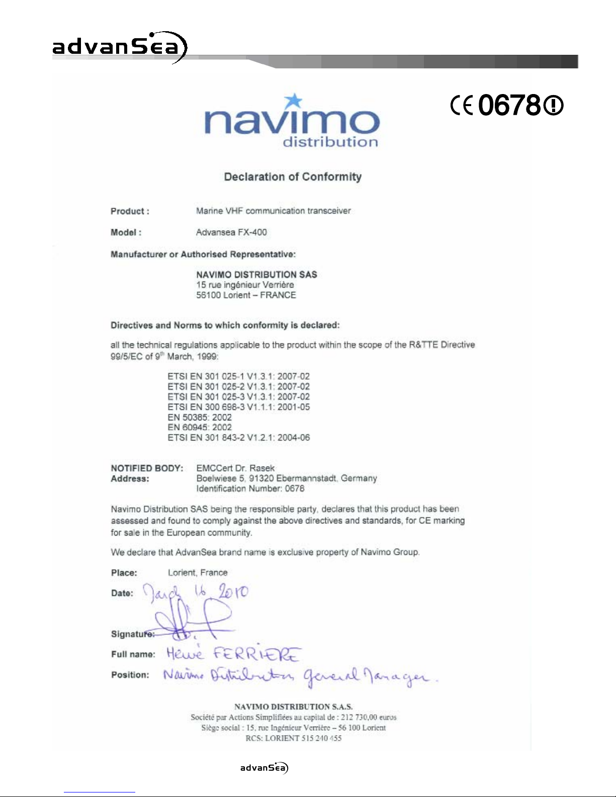
DECLARATION OF CONFORMITY .....................................................2
1. GENERAL INFORMATION.............................................................5
Introduction.............................................................................. 5
2. LICENSE INFORMATION..............................................................5
2.1 Digital Selective Calling (DSC) Capability ................................7
2.2. Required License Information ............................................... 7
2.3 Equipment Required.............................................................7
2.4 Equipment Supplied ............................................................. 7
3. BASIC RADIO COMMUNICATION PROCEDURES...........................8
3.1 Using Channel 16.................................................................8
3.2 Calling Another Vessel..........................................................8
3.3 Telephone Calls ................................................................... 9
3.4 Prohibited Communication .................................................... 9
4. INSTALLATION .........................................................................10
4.1 Transceiver....................................................................... 10
4.2 Antenna............................................................................ 10
4.3 Power Connection .............................................................. 10
4.4 NMEA Cable ...................................................................... 11
4.5 External Speaker Connection............................................... 11
4.6 Antenna Connector ............................................................ 11
4.7 Flush Mount Kit Installation................................................. 12
5. OPERATION ..............................................................................13
5.1 General ............................................................................ 13
5.2 Display and Controls .......................................................... 13
5.3 Basic Operation ................................................................. 14
Power On/Off .................................................................... 14
Volume and Squelch........................................................... 14
Channel Selection .............................................................. 15
Channel Banks .................................................................. 15
Keypad, Transceiver........................................................... 15
Keypad, Microphone........................................................... 16
6. OPERATIONG PROCEDURES......................................................16
6.1 Primary Calling Channel...................................................... 16
6.2 Transmitting...................................................................... 16
6.3 Working Channel Recall....................................................... 17
6.4 Transmitter Power Setting................................................... 17
6.5 Channel Scanning .............................................................. 17
Priority Scan ..................................................................... 18
All Scan............................................................................ 18
Memory Scan .................................................................... 18
6.6 Menu Functions.................................................................. 20
6.7 Main Menu Topics............................................................... 21
Directory .......................................................................... 21
Lamp................................................................................ 24

User manual FX-400 - 5 -
Contrast ........................................................................... 24
Data Set........................................................................... 25
MMSID Set........................................................................ 27
ATIS Set........................................................................... 28
Time Set........................................................................... 28
NMEA Set ......................................................................... 29
GPS Alert.......................................................................... 30
CH Name .......................................................................... 30
CH Change (Automatic CH Change)...................................... 32
7. DSC OPERATION .......................................................................32
7.1 MMSID ............................................................................. 33
7.2 Sending a Distress Call....................................................... 33
7.3 Receiving Distress Calls ...................................................... 35
Distress Sent by another vessel........................................... 35
Distress ACK sent to another vessel ..................................... 37
Distress Relay from another vessel ...................................... 37
7.4 Normal DSC Calls............................................................... 38
Individual DSC Call ............................................................ 38
Directory Call............................................................... 38
Manual Call.................................................................. 40
All Ship's Call .................................................................... 42
Group Call......................................................................... 44
Position Send .................................................................... 45
Position Request................................................................ 46
7.5 Receiving DSC Calls ........................................................... 47
Individual Call Received...................................................... 48
Last Call Received.............................................................. 49
All Ship's Call Received....................................................... 49
Group Call Received ........................................................... 51
Position Send Received....................................................... 52
Position Request Received................................................... 52
8. ATIS OPERATION......................................................................53
8.1 ATIS Set........................................................................... 53
8.2 ATIS ID ............................................................................ 53
9. REFERENCE...............................................................................54
9.1 Maintenance...................................................................... 54
9.2 Special Functions............................................................... 55
Clear Memory Channels...................................................... 55
New Microphone ................................................................ 55
Printer Operation ............................................................... 55
9.3 Troubleshooting................................................................. 56
9.4 Specififcations ................................................................... 57
9.5 Channel Assignments ......................................................... 61

User manual FX-400 - 6 -
1.GENERALINFORMATION
Congratulations on your purchase of the FX-400. It is an advanced marine
VHF communication transceiver offering Digital Selective Calling, an easy to
use four line LCD display, and a separate Channel 70 receiver.
NOTICE
Unauthorized changes or modifications to this equipment may void
compliance with Regulatory Agency Type Acceptance. Any changes or
modification must be approved in writing by the manufacturer.
NOTICE
This radio transceiver has been tested and complies with EN-301 025-1
v1.3.1 (February 2007). This specification provides reasonable protection
against harmful interference in a normal installation. This radio generates,
uses and radiates radio frequency energy and, if not installed and used in
accordance with the instructions, may cause harmful interference to other
marine electronic equipment. However, there is no guarantee that
interference will not occur in a particular installation. If this radio does
cause harmful interference to marine electronic equipment, which can be
determined by turning this radio Off and On, the user is encouraged to try to
correct the interference by one or more of the following measures:
•Reorient or relocate the antenna.
•Increase separation between this radio and other marine electronic
equipment.
•Connect this radio to a power source different from that of other
marine electronic equipment.
•Consult your dealer or an experienced technician for help.
Introduction
Your FX-400 VHF Transceiver is designed for operation in the marine VHF FM
frequency band. The operating frequency range is 156.025 to 162.000 MHz
which includes all currently allocated International channels.
The transceiver has Digital Selective Calling (DSC) capabilities conforming to
EN-301 025-1 v1.3.1 operation. Distress, All Ships, Individual and Group
DSC call formats are supported. There are thirty two memories for storing
incoming DSC calls and thirty two for your personal DSC call directory.
Other features include Position Send/Request, all channels scanning, priority
channel scanning, memory channel scanning, one button instant access to
channel 16 and an alphanumeric keypad on the microphone.
2. LICENSE INFORMATION
Your FX-400 complies with European Standard EN-301 025-1 v1.3.1. Users
must know and comply with all applicable rules and regulations for the
country or countries having jurisdiction over waters where your transceiver

User manual FX-400 - 7 -
is operated. Depending upon national regulations, a station license may be
required for a VHF transceiver and an operator license or permit may be
required for an individual to operate a VHF transceiver.
Prior to using your FX-400 inquire with your national radio communication
authorities.
2.1 Digital Selective Calling (DSC) Capability
You must obtain a nine-digit maritime mobile service identity (MMSI) and
program it into the unit before you transmit. To obtain an MMSI, you will be
asked to provide certain information about your ship. It is important that
you obtain an MMSI because National Coast Guards and other search and
rescue (SAR) agencies use this information to help speed search and rescue
operations.
2.2 Required License Information
The following information pertaining to your transceiver is necessary if
completing a station license application
Output Power....................................... 1 Watt (low) and 25 Watts (high)
Emission..................................................................16K0F3E, 16K0G3E
Frequency Range..............................................156.025 to 162.000 MHz
Meets Essential Requirements of RTTE DIRECTIVE (Declaration of
Conformity)
2.3 Equipment Required
The minimum equipment required for two way voice and DSC VHF radio
communication with vessels and shore stations includes:
•VHF radio communication transmitter and receiver designed and
approved for marine VHF communication use.
•VHF antenna and connecting cable. Use a good quality unity gain
antenna for best range performance.
•Power source suitable for the VHF transmitter and receiver.
•For Digital Selective Calling (DSC) VHF communication radios,
connection to a GPS receiver that provides latitude and longitude
coordinates and UTC time for distress messages.
2.4 Equipment Supplied
•FX-400 Marine VHF Transceiver.
•Microphone with alphanumeric keypad.
•Mounting Bracket with knobs.
•Power Cable with in-line fuse (6.3 Amp).
•NMEA Data Cable.
•Flush Mounting Kit.
•Protection cover.

User manual FX-400 - 8 -
3. BASIC RADIO COMMUNICATION PROCEDURE
Distress or emergency calls may be made either manually or automatically.
Sending distress calls automatically uses the Digital Selective Calling (DSC)
functions of your transceiver and requires an operating and properly
connected navigation receiver. The following procedures are for sending
voice distress messages manually. Sending an automatic distress call is
described in the DSC section of this manual.
3.1 Using Channel 16
Channel 16 is the Calling and Distress channel. An emergency may be
defined as a situation that threatens human life or property. In such
situations, make sure your transceiver is turned On and set the channel
selector to Channel 16. Then use the following procedure to make a distress
call. The total transmission should not exceed 1 minute.
1. Press the microphone Push To Talk button. Speak slowly and
clearly into the microphone: “Mayday, Mayday, Mayday, this is
your vessel’s name, your vessel’s name, your vessel’s name”.
2. Then repeat once: “Mayday, your vessel’s name”.
3. Continue by reporting your position in latitude and longitude or
by reporting your bearing (true or magnetic, specify which) and
distance from a prominent or well known landmark, geographic
feature or aid to navigation.
4. Explain the nature of your emergency (fire, sinking, collision,
grounding, health condition, injury, etc.).
5. Report the kind of assistance you require (fire, medical aid,
pumps, etc.).
6. State the number of people aboard and the condition of any
injured.
7. Estimate the seaworthiness and condition of your vessel.
8. Describe your vessel: length, type, color and any distinguishing
feature.
9. End the message by saying “Over”. Release the Push To Talk
button and listen for a reply.
10. If there is no reply, repeat the above message procedure. If
there is still no response, try another channel.
3.2 Calling Another Vessel
Channel 16 may be used to establish initial contact with another vessel.
However, its most important use is for voice emergency messages. Channel
16 must be monitored at all times except when engaged in actual
communication on another channel. Channel 16 is monitored by
international search and rescue (SAR) authorities, National Coast Guards

User manual FX-400 - 9 -
and by other vessels. Use of Channel 16 for calling or hailing must be
limited to initial contact only. Calling should not exceed 30 seconds and
may be repeated 3 times at 2 minute intervals.
Prior to making contact with another vessel, determine which channel will be
used for continued communication after the initial contact. Monitor the
desired channel for traffic and, when clear, switch to Channel 16 to make
initial contact.
Listen for traffic on the Calling Channel (16). If clear, press the Push To Talk
(PTT) button on the microphone. Speak the name of the vessel you are
calling followed by “This is” and the name of your vessel and your call sign.
Release the PTT and listen for a reply. When the other vessel returns your
call, acknowledge the call with “go to”, the number of the new channel and
“over”. Switch to the new channel and listen for traffic. If necessary, wait
for traffic to clear, and then call the other vessel. As communication
proceeds, end each transmission with “over”. When communication with
the other vessel is completed, end the last transmission with your call sign
and the word “out”. It is not necessary to end each transmission with your
call sign, just give your call sign at the beginning and end of each contact.
Remember to switch to Channel 16 when not actively communicating on
another channel.
3.3 Telephone Calls
You may use your FX-400 transceiver to make telephone calls to persons on
shore. To do so requires the services of marine operators who operate on
designated Public Correspondence channels. There are several channels
designated for this type of traffic and to determine the channel being used in
your area, ask someone with local knowledge, contact a Harbor Master or
other marine authority.
Call the marine operator and identify yourself with your vessel’s name.
Normally you contact a marine operator on their working channel rather than
making initial contact on Channel 16. The marine operator will ask for your
intentions and establish a payment method for the call (collect, credit card,
etc.). When arrangements are complete, your radio communication will be
patched into the telephone line. In conversing with a person on the phone it
is important to use normal radio communication procedures. You should
say ”over” and release the PTT button at the end of each transmission.
Both parties cannot speak simultaneously as on normal telephone calls.
Usually there is a fee for marine operator services which is charged in
addition to any other charges associated with the call.
3.4 Prohibited Communication
The following communications are prohibited by regulations and violators are
subject to penalties:

User manual FX-400 - 10 -
•False distress or emergency messages (including false DSC distress).
•Messages to “any vessel” except in emergencies and radio tests.
•Messages to or from a vessel on land.
•Transmission while on land.
•Obscene, indecent, or profane language.
4. INSTALLATION
4.1 Transceiver
Your FX-400 Transceiver is designed to withstand the rigors of the marine
environment. However, selecting a mounting location affording some
protection from the elements will prolong the life of connectors, controls and
the liquid crystal display (LCD).
Select a location within easy reach and view of the operator and away from
your vessel’s compass. Locate the microphone to avoid entanglement with
steering or engine controls, both when in use and when stowed. Also,
consider routing of antenna, power and NMEA interface cables. Mount the
transceiver securely to a solid surface.
4.2 Antenna
Proper installation of a quality VHF antenna is very important to reliable radio
communication. A good quality unity gain antenna is recommended for
maximum range performance. In general, antennas should be located as
high as practical and separated as much as possible from other antennas and
structures. The minimum distance to other objects is 1 meter. Route the
antenna cable away from other electronic equipment and do not bundle the
antenna or power cable with other wiring, especially transducer cables for
depth sounders and fish finders. For cables longer than 10 meters, RG-8/U
coaxial cable must be used. Mount the antenna and install the connector(s)
in accordance with manufacturer’s instructions. Connect the antenna cable
to the RF output connector on the rear panel of the transceiver.
4.3 Power Connection
CAUTION
Reverse polarity connections can damage your transceiver
The power cable for you transceiver must be connected to the ships main
power buss. Use the 6.3 Amp in-line fuse provided. Connect the Red wire
to the positive (+) terminal and the Black wire to the negative (-) terminal.
Connect the barrel terminals on the power cable to the matching color wires
and terminals extending from the rear panel of the transceiver.

User manual FX-400 - 11 -
4.4 NMEA Cable
In order for the position reporting/transferring features of your FX-400
transceiver to function, an operating GPS navigation receiver must be
connected to your transceiver. The supplied data cable plugs into the 8 pin
connector on the transceiver’s rear panel and the other end connects to the
NMEA data output/input from your GPS navigation receiver. Your GPS must
adapt for the $GPGLL/GGA/RMC/GNS NMEA data sentence. Refer to your
navigation receiver manual for information about its NMEA output/input
settings and connections.
Wire Color Description Connection
1. Brown NMEA Rx(+) Connect to NMEA Tx(+) of GPS
2. Red NMEA Rx(-) Connect to Ground/NMEA Tx(-) of GPS
3. Orange NMEA Tx(+) Connect to NMEA Rx(+) of GPS
4. Shield Ground/NMEA Tx(-) Connect to Ground/NMEA Rx(-) of GPS
Pins 3 & 4 reserved for DSC/PC printer interface
Pins 5-8 reserved for Flash programmer
4.5 External Speaker Connection
Provision for connecting and external speaker is provided on the rear panel.
Use an 8 Ohm speaker rated for at least 3 Watts and suitable for the
environment at the chosen location.
3.5 mm Phone plug
Tip Audio Out(+)
Body Audio Out(-)
4.6 Antenna Connector
The transceiver is fitted with a type SO 239 female connector which mates
with a PL 259 male connector supplied with VHF marine antennas.

User manual FX-400 - 12 -
4.7 Flush Mount Kit Installation
1. Cut the dash board using a template sheet included in the package.
2. Set the radio in the cut dash board.
3. Rotating the longer screw and set it to the hole of the plastic mount
block. Firmly attach the bolt foot rotating to the top of the screw. (See
Fig. 1)
4. Firmly fix the plastic mount block on the either side of the radio using
shorter screw. Don’t forget to attach the washer. (See Fig. 2 and Fig.
3)
5. Fasten the longer screw to fix the radio to the dash board firmly. (Fig.
4)
The same works should be done to the other side too.
Fig. 1
Plastic mount block
Longer screw Bolt foot
Fig. 2
Washer
Shorter screw
Fig. 3 (+) screw driver Fig. 4
User manual FX-400 - 13 -
5. OPERATION
5.1 General
Your FX-400 is an advanced marine VHF communication transceiver offering
the safety and convenience of Digital Selective Calling in addition to all the
useful features found in the best conventional VHF radios.
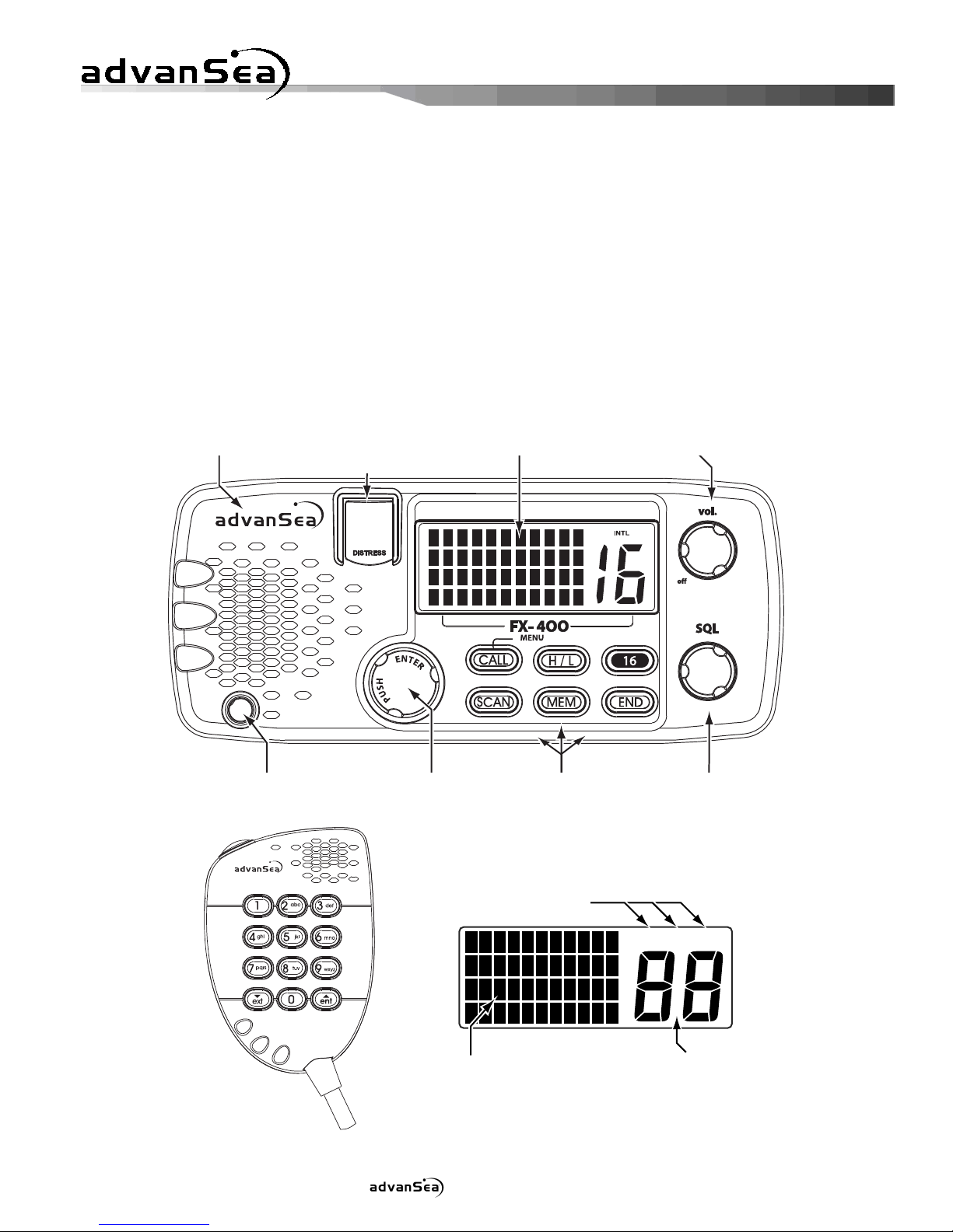
5.2 Display and Controls
The transceiver is operated using the front panel controls, the keypad, the
Push To Talk (PTT) button and a keypad on the microphone. The 4-line LCD
displays the current operating status, menus for selecting functions, and
settings for optional features. The microphone has a keypad for changing
channels and selecting functions.
MT-500
USA INT CAN
FX-400
Internal Speaker LCD DisplayEmergency Button
Under Cover Volume Control
Microphone
Cable Entry Channel/Data
Selector Keypad Squelch Control
Liquid Crystal Display
Frequency Bank
Annunciators
4 lines, 11 characters each
for alphanumeric information Channel
Number
User manual FX-400 - 14 -
5.3 Basic Operation
Power On/Off
Power to the transceiver is controlled with the VOLume knob. When the
VOL knob is in the full CCW position the unit is turned Off.
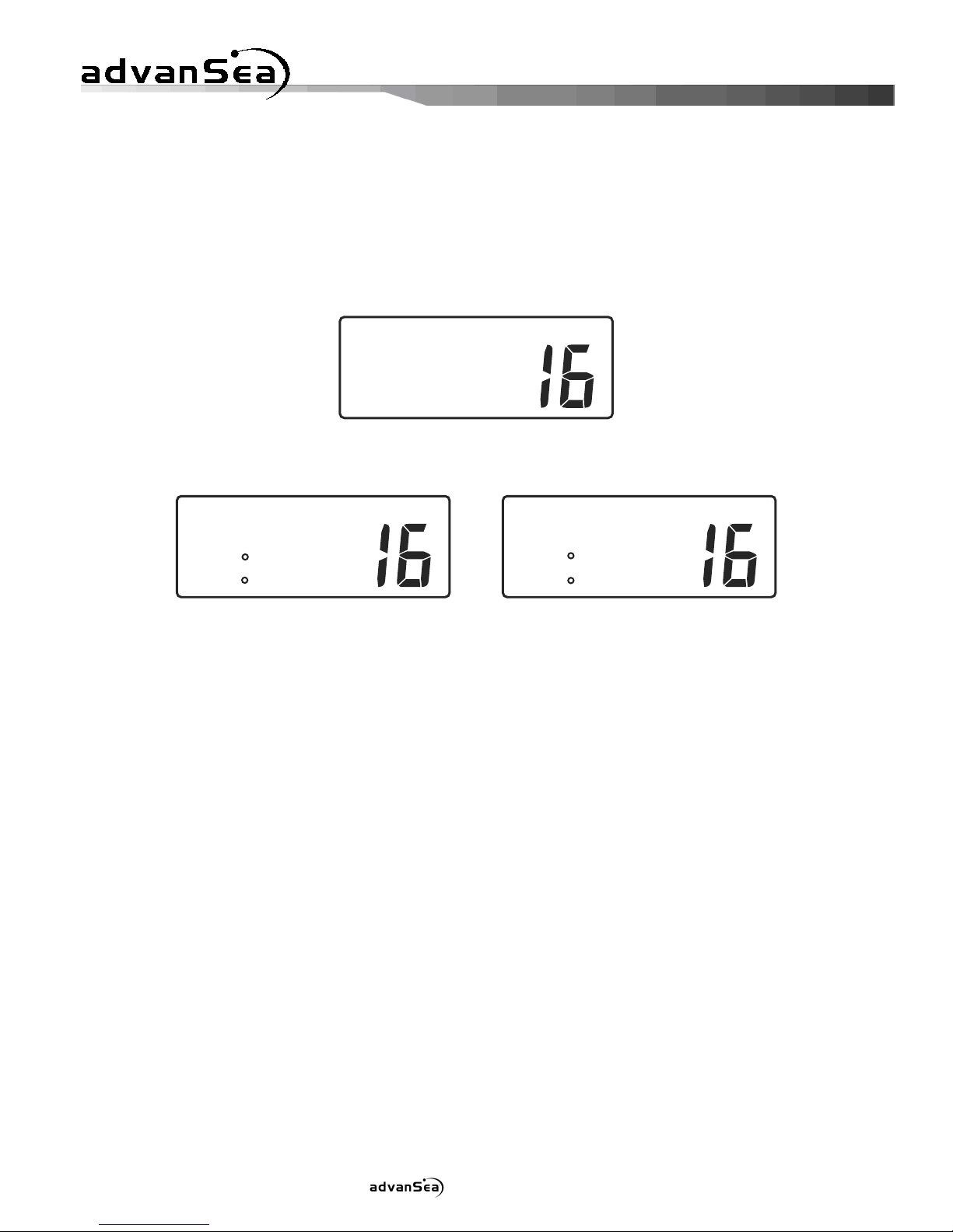
To turn the transceiver On:
•Rotate the VOL knob CW until it clicks over the detent. The LCD
backlight illuminates and the Power-On screen appears.
INT
FX-400
CODE 000.00
Power-On Screen
After approximately two seconds, the Normal Communication screen
appears in the display.
INT
16 PRI. HI
MEM CHANNEL
N 28 04.814
W 83 42.169
INT
16 PRI. HI
MEM CHANNEL
99 99.999
999 99.999
Normal Com Screen Normal Com Screen
withGPSConnected w/oGPSconnected
To turn the transceiver Off:
•Rotate the VOL knob CCW until it clicks over the detent to the OFF
position.
Volume and Squelch
The VOLume and SQuelch controls have each knob. They are independent
controls but work together to control audio output from the speaker. The
volume control sets the loudness of sound from the speaker and the squelch
control is used to mute background noise when no received signals are
present.
To properly set the VOL and SQ controls:
•Rotate the SQ knob fully CCW.
•Rotate the VOL knob CW until background noise is plainly heard.
•Slowly rotate the SQ knob CW until the noise is muted (squelched).
Then adjust the control slightly more CW (approximately 1/8 turn).
Use care not to set the SQ control more CW than necessary or weak
signals may not be heard.
Some channels exhibit more background noise than others, so it may be
necessary to readjust the squelch setting when changing channels or when
scanning.
User manual FX-400 - 15 -
Channel Selection
When the transceiver is turned On, the Primary Calling Channel (channel 16)
is selected.
There are three ways to change channels:
•Rotate the (SELECT/ENT) knob, press and hold the or
keys, or directly enter the channel number using the numeric
keys on the microphone. The and keys will always
change channels except when being used to enter or edit a directory
page.
Channel Banks
Your FX-400 is designed for use with the International VHF marine channel
frequencies plus authorized local channel frequencies. Only authorized
dealers can program other approved country channels, where specifically
allowed by government regulations, by using the 8 pin com connector.
Keypad, Transceiver
A tone is emitted each time a key is pressed. A three beep error tone is
emitted when a key is not allowed. Some functions require a key to be
pressed and held. After the hold period times out, a second tone is emitted
as the function is entered. The basic purpose for each key follows.
Detailed usage of keys is described in operating procedures for the
transceivers various functions.
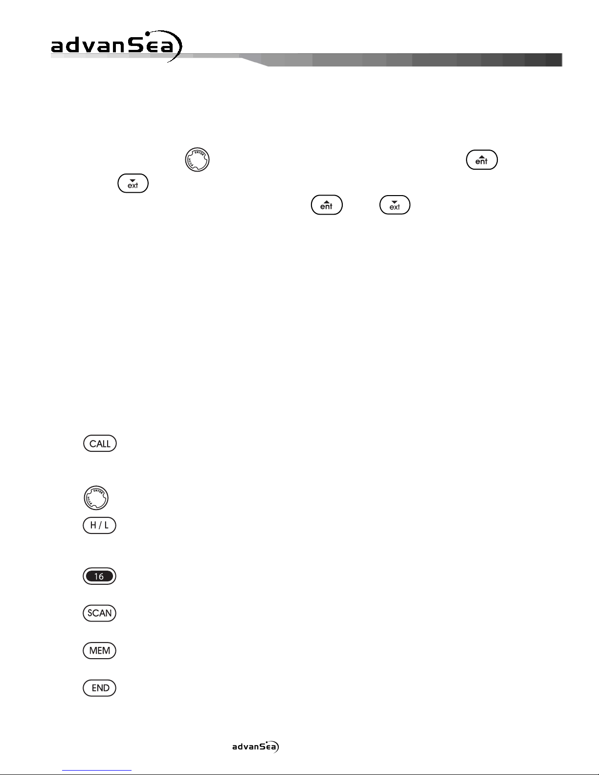
Initiates DSC operation screens by pressing. Also opens menu to
select optional settings to personalize your transceiver’s
operation by pressing and hold.
Used to complete editing or selection of options from menu.
Use to toggle transmitter power between 25 watts and 1 watt
output. Certain channels are restricted to 1 watt maximum
power and will cause the error beep if the HI/LO key is pressed.
Selects the Primary Calling Channel 16 or the last channel used.
Also, cancels DSC and Emergency/Distress calls.
Can be used alone or with the MEM key to select Priority Scan,
Memory Scan or All Scan.
Stores channels in the scan memory bank, and when used with
the SCAN key, starts Memory Scan.
Cancels DSC calls and Emergency/Distress calls.
Keypad, Microphone

User manual FX-400 - 16 -
The microphone keypad is used to change channels by directly entering the
actual channel number with the through keys. The or
keys step or scroll to a new channel. The microphone keys are used
to enter alphanumeric characters and symbols shown in the following chart.
Microphone Keys
Alphanumeric Character Sequence
6. OPERATING PROCEDURES
6.1 Primary Calling Channel
VHF Channel 16 (156.8 MHz) is the Distress Safety and Primary Calling
Channel. All vessels, not actively engaged in communication, are required
to maintain a listening watch on Channel 16.
6.2 Transmitting
The transmitter is activated, for normal voice communications, by pressing
the Push To Talk (PTT) button on the microphone. Always listen for
moment on a channel before transmitting. If the channel is busy, do not
transmit until the channel is clear. For DSC calling and Distress calls, the
transmitter is activated automatically during the appropriate operating
procedure. After DSC contact is established, proceed as in normal voice
communication. Continuous transmitter operation is limited to five minutes
and the transmitter will automatically stop.
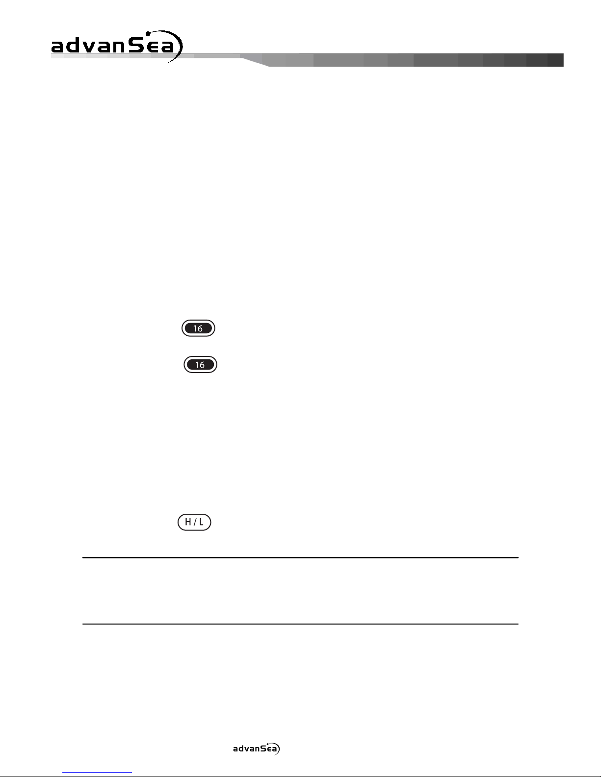
To establish normal voice communication:
•Press the key to select the Primary Calling Channel. The
Primary Calling Channel is 16. The Primary Calling Channel number
appears in the upper left corner of the display.
•Listen on the Primary Calling Channel to make sure the channel is
clear.
•Press the PTT button. Speak directly into the microphone in a normal
tone of voice --clearly--distinctly. Say “(name of vessel being called)
THIS IS (your vessel’s name and call sign).”
Space
User manual FX-400 - 17 -
•Release the PTT button and listen for a reply.
•Once contact is made on the Primary Calling Channel, each vessel
must switch to a working channel to continue conversation. Refer to
the channel chart for proper usage.
•After communication is completed, each vessel must give its call sign
or vessel name and switch to the Primary Calling Channel and resume
listening watch.
6.3 Working Channel Recall
Rather than using the SELECT/ENT knob or microphone keys to change
channels, this feature allows quick switching between the last working
channel and the current primary channel.
To quickly switch between the last working channel and the Primary Calling
Channel:
•Use the SELECT/ENT knob or microphone keys to select a working
channel, such as channel 68.
•Press the key momentarily. The current primary channel
number appears in the channel number display.
•Press the key again momentarily. The working channel
number appears in the display. Each time the key is pressed, channel
selection toggles between the primary channel and the working
channel.
6.4 Transmitter Power Setting
The transmitter has two power settings, 25 watts or 1 watt, which are
indicated by HI or LO appearing in the upper line of the display. The normal
power setting is HI for all channels where 25 watts is allowed. Use the 1
watt setting for communication with nearby vessels (bridge-to-bridge) or
facilities (drawbridges).
•Press the key to toggle transmitter power between 25 watts
and 1 watt output.
SPECIAL NOTE
Channels 15, 17, 75 and 76 are restricted to 1 watt maximum power and will
cause the error beep if the HI/LO key is pressed.
6.5 Channel Scanning
There are three channel scanning modes; Priority Scan, All Scan and Memory
Scan. In the Priority Scan mode, Channel 16 is checked for activity every 2
seconds, even if, the scan is halted by traffic on a working channel. When
scanning is halted by traffic, the scan pauses while the channel is active.
User manual FX-400 - 18 -
Scanning resumes, after a brief delay when the channel is clear. If the PTT
is pressed, in reply to a received signal, scanning is cancelled.
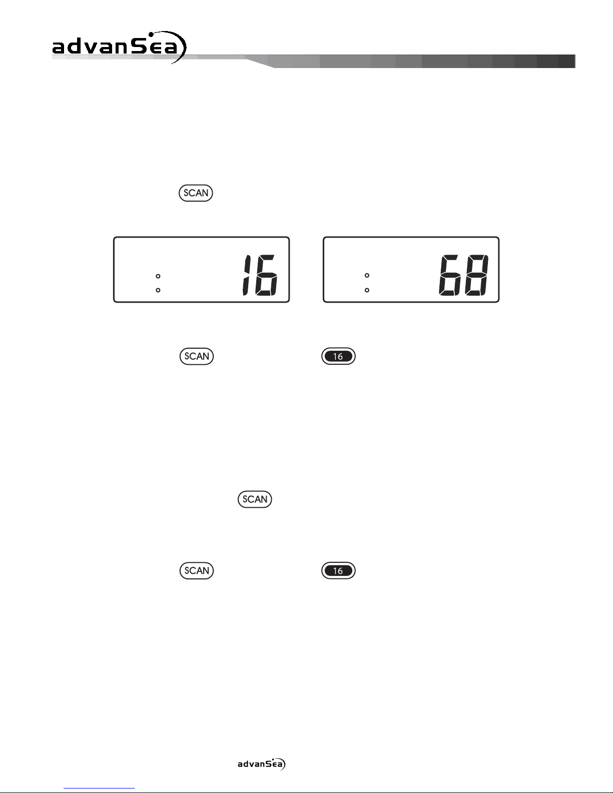
Priority Scan
The Priority Scan function scans the Primary Calling Channel and the last
selected working channel.
To select Priority Scan:
•Press the key. PSCAN appears in the upper line of the display
and the two scanned channel numbers appear alternately in the
display.
INT
PSCAN HI
08Dec12:05P
N 28 04.814
W 83 42.169
INT
PSCAN HI
08Dec12:05P
N 28 04.814
W 83 42.169
Priority Scan Sequence
To exit Priority Scan:
•Press the key or press the key.
All Scan
The All Scan function scans all channels except channel 70. Channel 70 is
the Digital Selective Calling (DSC) channel. Voice traffic is not permitted on
this channel. If noisy or busy channels interfere with scanning, the
interfering channels may be temporarily removed from the scan sequence.
To select All Scan:
•Press and hold the key for 2 seconds. ALLSCAN appears in
the upper line of the display. The scanned channel numbers appear in
sequence in the channel number display.
To Exit All Scan:
•Press the key or press the key.
To delete channels from the scan sequence:
•Push and hold the SELECT/ENT knob while the scan is halted on the
offending channel. Turning the transceiver Off and On, restores all
channels to the scan sequence.
Memory Scan
Memory Scan allows the user to create and scan a bank of preferred channels.
Channels may be added to or removed from the memory channel bank as
desired. Memory channels are stored individually and may be deleted
individually, or the entire bank may be deleted. If the PTT button is pressed,

User manual FX-400 - 19 -
the transceiver exits scanning and normal communication is resumed.
To create or add channels to the memory channel bank:
•Press the key. The Memory Scan channel bank appears in
lower two lines of the display. If no channels have been previously
added to the bank, the Primary Calling Channel (16) is displayed.
Otherwise, up to six channel numbers appear. A plus sign (+) at the
end of the lower line indicates more than six channels are stored in the
bank. Press the key again to advance to the next page of
channels. The memory channel bank can hold all usable voice
communication channels.
INT
ADD/DELETE
MEM CHANNEL
16
INT
ADD/DELETE
MEM CHANNEL
06 09 16
22 67 68 +
INT
ADD/DELETE
MEM CHANNEL
72 78
Memory Scan Bank Memory Scan Bank Memory Scan Bank
DefaultPage PageFull NextPage
•Rotate the SELECT/ENT knob or microphone keys to select a desired
channel to add to the memory channel bank.
•Press and hold the key for about two seconds. The selected
channel is stored and the channel number appears in the memory
channel bank. Repeat the select and store process to add more
preferred channels. As each channel is added, the existing channels
in the bank shift as necessary to display the new channel number in the
bank.
When in the normal communication mode, as channels are selected,
MEM CHANNEL appears in the second line of the display if the
selected channel is stored as a memory channel.
INT
16 PRI. HI
MEM CHANNEL
N 28 04.814
W 83 42.169
Memory Channel Display
To remove channels from the memory channel bank:
•Press the key. The Memory Scan channels appear in the
display.
•Rotate the SELECT/ENT knob or use microphone keys to select a
displayed channel.
•Press and hold the key for about two seconds. The selected
channel is deleted and the channel number is removed from the
memory channel bank.

User manual FX-400 - 20 -
To remove all channels from the memory channel bank:
•Turn the transceiver Off.
•Press and hold the key while turning the transceiver On. The
memory channel bank is erased except for Channel 16 which remains.
To start Memory Scan:
•Press the key. The Memory Scan channel bank appears in the
display.
•Press the key. MSCAN appears in the upper line of the display.
The scanned channel numbers appear in sequence in the channel
number display.
6.6 Menu Functions
Menus are used to customize optional settings to individual preference. The
multilevel menu system is a list of topics that, when selected individually,
offer options or additional related topics from which to choose. Changes to
menu settings are stored and remain in force until changed again.
To navigate through menus:
•Press and hold the key. The Main Menu appears in the display.
DIRECTORY is always the first topic displayed on the Main Menu list.
INT
>DIRECTORY
LAMP
CONTRAST
DATA SET
Main Menu Topics
To select a topic in the menu list:
•Rotate the SELECT/ENT knob to move the cursor >to the desired
topic. There are more topics than can be displayed at one time, so the
list scrolls as the cursor is advanced beyond the top or bottom of the
list.
INT
GPS ALERT
CH NAME
CH CHANGE
>DIRECTORY
More Main Menu Topics
•With the cursor on the desired menu topic, press the SELECT/ENT
knob. Options or edit settings for the topic appear in the display.
•Rotate the SELECT/ENT knob to move the cursor to the desired
setting.
Table of contents
Languages:
Popular Radio manuals by other brands


RCA
RCA RIR205 - Infinite Radio Tabletop Internet quick start guide

SOUNDMASTER
SOUNDMASTER TR480 manual

Busch-Jaeger
Busch-Jaeger Busch-AudioWorld 8217 U-101 product manual

Blaupunkt
Blaupunkt PP30BT JOBSITE owner's manual

argon audio
argon audio Radio1 user manual

Sirius Satellite Radio
Sirius Satellite Radio XTR3CK instruction manual