Pub. 42004-387G
GAI - TRONI CS
®
AHUBBELL COMPANY
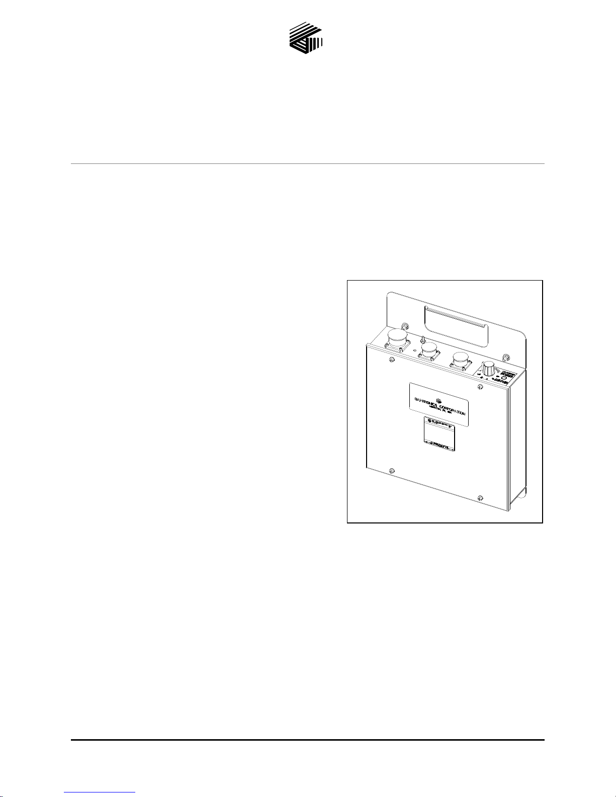
Model 4512-001, 4512-001FR, 4514-001
and 4514-001FR 6-Channel Radios
User and Installation Manual
TABLE OF CONTENTS
GAI-TRONICS 3030 KUTZTOWN RD. READING, PA 19605 USA
610-777-1374 800-492-1212 Fax: 610-796-5954
VISIT WWW.GAI-TRONICS.COM FOR PRODUCT LITERATURE AND MANUALS
Confidentiality Notice.....................................................................................................................1
General Information.......................................................................................................................1
Scope of Manual......................................................................................................................................1
Features and Functions ..........................................................................................................................1
Description ......................................................................................................................................2
Connectors...............................................................................................................................................3
Power Connector...................................................................................................................................................3
Speaker Connector ................................................................................................................................................4
Microphone Connector .........................................................................................................................................4
Antenna Connector ...............................................................................................................................................4
Channel Selector Switch.........................................................................................................................4
Radio Transceiver Module.....................................................................................................................5
Interface PCBA.......................................................................................................................................5
Pot R7 ...................................................................................................................................................................5
Wide Range (110/220 V AC/270 V DC) Power Supply PCBA............................................................6
Pot 2......................................................................................................................................................................6
Surge Filter PCBA..................................................................................................................................6
Optional Standby/Emergency Battery..................................................................................................7
Installation ......................................................................................................................................8
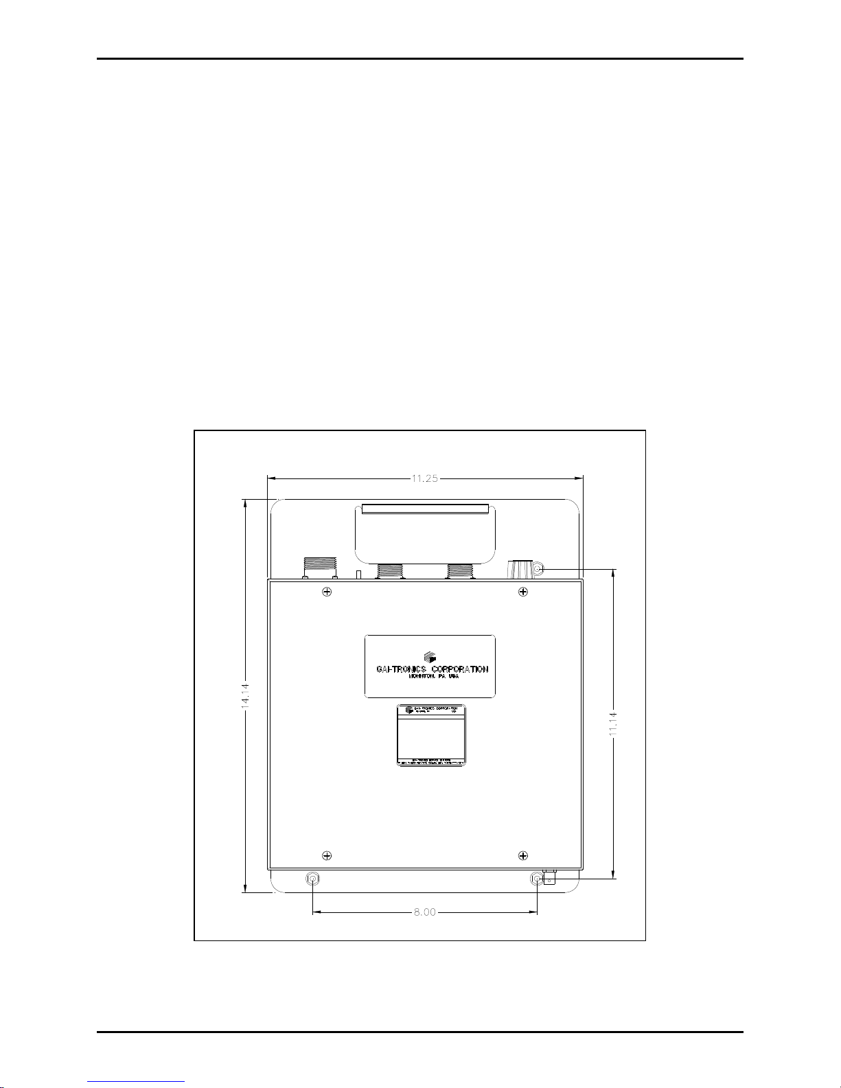
Mounting..................................................................................................................................................8
FCC Interference Warning....................................................................................................................8
Safe Handling of CMOS Integrated Circuit Devices...........................................................................9
Equipment Required ............................................................................................................................10
Test Equipment ...................................................................................................................................................10
Cable Installation Safety Considerations............................................................................................10
Surge Protection....................................................................................................................................10
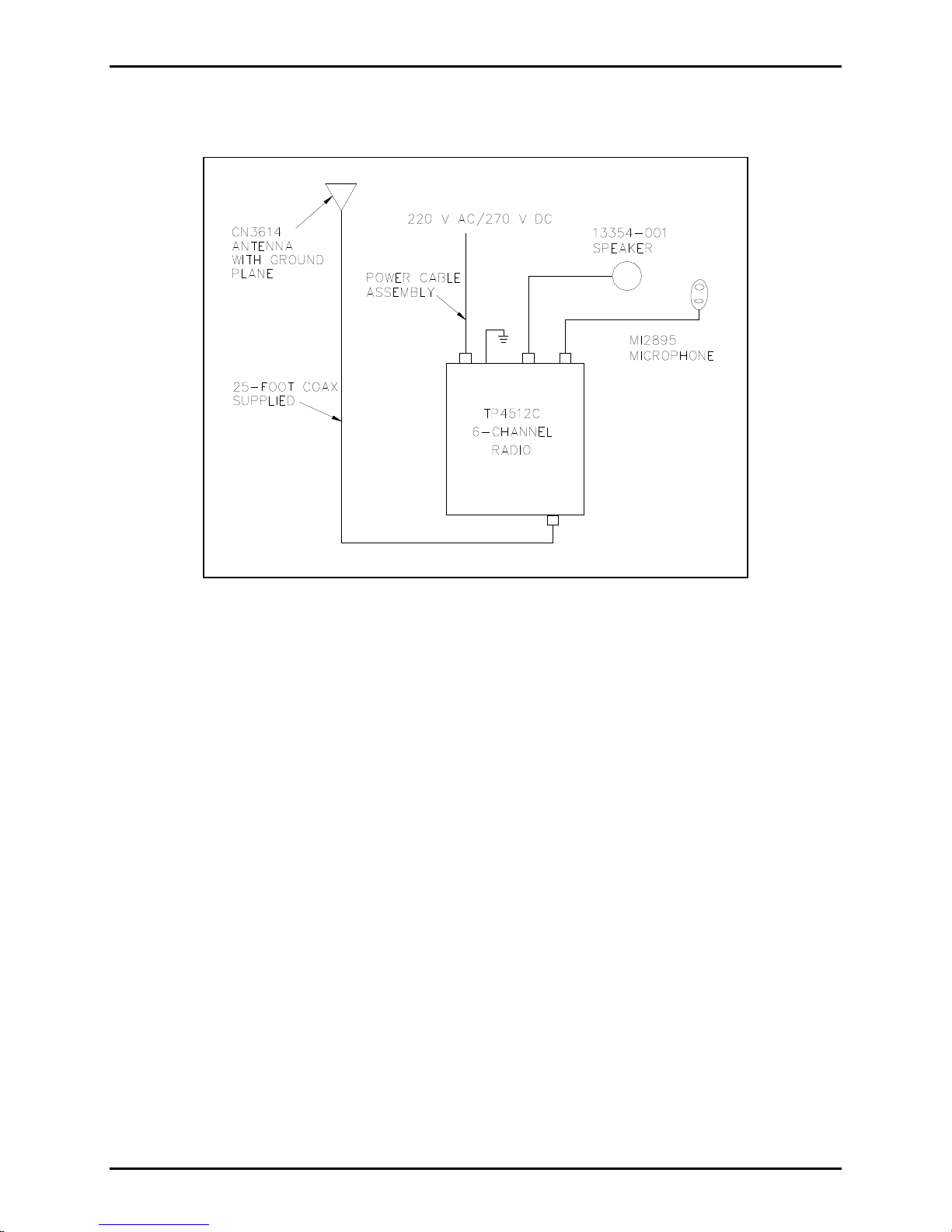
Antenna Connection .............................................................................................................................11
Power Connections................................................................................................................................13
Models 4514-001 and 4514-001FR ....................................................................................................................13
Models 4512-001 and 4512-001FR ....................................................................................................................13