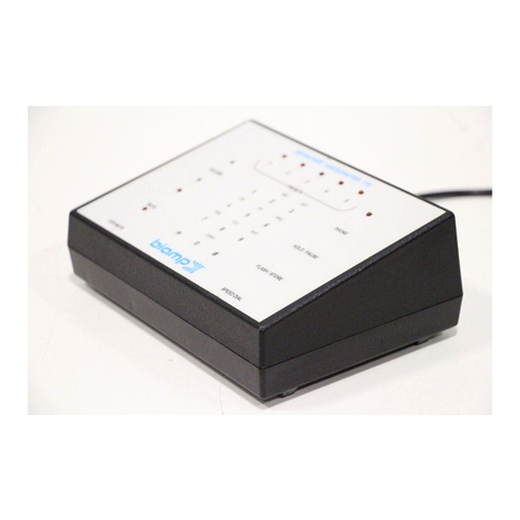
Advantage MicroTron User manual

1
Installation
Maintenance
Repair
Manual
Advantage Controls
P.O.Box 1472
Muskogee, OK 74402
Phone: 800-743-7431
Fax: 888-686-6212
www.advantagecontrols.com HE-22
1/08
MicroTron
Timer Controller
Manual

2
MicroTron Timer Controller
Instruction & Maintenance Manual
Table of Contents
Contents Page No.
I. Introduction...................................................................................... 3
Model Numbering ............................................................................ 3
II. Description....................................................................................... 3
III. Installation
Electrical Wiring............................................................................... 4
Conduit Layout for LCD Display ...................................................... 4
Mounting Instructions ...................................................................... 5
Typical Installations ......................................................................... 5
IV. Front Panel Description ................................................................... 6
V. System Operation Overview............................................................ 7
A. Description of Set Up Menu Screens ......................................... 7
1. Chem Feed Set..................................................................... 8
2. Biocide Set ............................................................................ 9
3. Clock Set............................................................................. 10
4. System Set Menu................................................................ 11
5. Diagnostics Menu................................................................ 13
B. Run Menu ................................................................................. 14
VI. Troubleshooting........................................................................ 14
VII. Warranty & 30 Day Billing Memo Policy ................................... 15
Instructions herein apply to all Microtron chemical feed or biocide timers
or combinations of the two. Additional options described in this manual may
or may not be present on your unit. Refer to Model Numbering on Page 3.

3
I. Introduction
MicroTron controllers are microprocessor based menu driven units for control of recirculating water applications.
All settings are entered into the controller through a simple front panel keypad which includes relay test
keys.
Model Numbering
Base Functions
All model numbers can be broken down as
follows and will start with an M or L:
MMicroTron with a VFD display
L MicroTron with an LCD display
FSingle programmable feed timer
F-2 Dual feed timers
F-3 Triple feed timers
F-4 Quadruple feed timers
BSingle 28 day timer
B-2 Dual 28 day timers
B-3 Triple 28 day timers
II. Description
Selectable Timers
Selectable timers (base function F) are designed to automate the addition of various chemicals or activation
of other devices via a relay output. Multiple timers can be supplied depending upon the model number, and
each timer will include a relay output. All timers can be programmed to be one of the following types:
1. Pulse Timer – This timer accepts dry contact pulses from a make-up water meter (supplied
separately). It can accumulate 1-250 pulses to activate the timer to run from 0-99 minutes, 59
seconds in minutes and seconds.
2. Percentage – The relay is on for a percentage of a continuously repeating cycle time. Both the
percentage and cycle time are programmable.
28-Day Feed Timers
28-day feed timers, typically used for biocide feed are based on a 28-day cycle with two independent
programmable feed cycles allowing for feed on selectable days and weeks. The biocide timers on units
with selectable timers also include bleed lockout settings. Multiple timers can be supplied depending upon
the model number, and each timer will include a relay output.
MicroTron timer controllers have several base functions and optional features available. Your unit may be
supplied with one or more of the options that are described in this manual. To determine what features apply
to your unit, check the model number label located on the controller enclosure.
Optional Features
This list represents our most popular options.
A Conduit connections
A-6 On/Off power switch
A-7 Lower enclosure
D220 V service (conduit only)
EMounted ow switch assembly
MAlarm relay output
M-1S Sonic alarm buzzer with silence switch
VDigital input for bleed-off water meter
WPower relay 1.5 HP max, 25 amps
XTank low level alarms
Z-9 Chem A lockout with biocide

4
III. Installation
Electrical Wiring
The standard MicroTron Timer controller has an internal regulated power supply that will operate in the range
of approximately 90 to 240 VAC on the incoming wiring. Output relay(s) are protected with a replaceable fuse.
Relay output voltage will equal the incoming line voltage.
Prewired units are supplied with a 16 AWG cable with a 3-wire grounded USA 115 volt plug for incoming power
and 18 AWG 3-wire grounded receptacle cords for all control relay outputs.
Conduit units are predrilled at the factory and supplied with conduit knockouts for easy hard wiring to supplied
connectors.
NOTE: Liquid tight ttings and some labeled signal leads are provided for all signal (low voltage)
connections, such as water meter, low drum level, ow switch and 4-20mA outputs.
WARNINGS:
1. The controller should be connected to its own isolated circuit breaker, and for best
results, the ground should be a true earth ground, not shared. Wiring must be done
according to all applicable local codes.
2. Power (line voltage) must be disconnected while making any connections. If power is
supplied to the unit, line voltage will be present on the relay cards.
3. Low voltage signal wires (probes, ow switch, water meter, etc.) should never be run
in conduit with high voltage wires.
!
Conduit Connections for LCD Units
Relay / Power BoardLogic Board
Serial Line
Connection
R
B
R
B
R
B
R
B
Level 1
Level 2
Level 3
Level 4
Water
Meter
Input
Make/up
Switch
Make/up
Cal.
Make/up
Cond.
Probe
R
B
ISO
4-20
Out
To 4-20
Board
LCD
Contrast
TP-6 TP-7
Red
Green
Black
White
TP-3
GND
TP-4
TP-2
TP-5
TP-1
-5 +5
-12 +12
R
B
R
B
R
B
R
B
R
B
Pulse 1
Pulse 2
Pulse 3
Pulse 4
Bleed Meter
Flow
R +12 VDC
B GND
B
R
W
G
B
R
W
G
Eprom
ADJ.
TP6
Cond. Switch
OFF / ON
Cond.
Cal.
Conductivity
Probe
OFF
ORP
Test
OFF
ORP
Test
10 9
21
Ribbon
Cable
for Relays
SIGNAL
GROUND
+ vdc for option 9
Relay 5
Relay 3Relay 2Relay 1 Relay 4
POWER SUPPLY
Relay / Power Card (REV D)
Green
White
Red
Black
FUSE
FUSE
FUSE
FUSE
FUSE
1
Relay 1
2
Relay 2
4
Relay 4
35
N.O N.C NET GRD
N.O N.C NET GRD
N.O N.C NET GRD N.O N.C NET GRD
N.O N.C NET GRD
H N G
POWER INPUT
Ribbon Cable
1
2
9
10
Actual connection present depend on options ordered. Drawing is for referce only.

5
Mounting Instructions
Select a mounting location that provides the operator easy access to the unit and a clear view of the controls
through the cover of the controller. The unit should be located convenient to grounded electrical connections,
the required sample line plumbing, and installed on a stable vertical surface.
WARNING:
Avoid locations that expose the controller to direct sunlight, vapors, vibration, liquid
spills or extreme temperatures; less than 0°F (-17.8°C) or greater than 120°F (50°C). EMI
electromagnetic interference from radio transmissions and electric motors can also cause
damage or interference and should be avoided.
!
B L OWDOWN
S OL E NOID
V A L V E
C O O L ING T O WE R
C IR C UL A T IO N P UMP C HIL L E R
MA K E -U P
W A T E R ME T E R
Throttling device
Electrically actuated
blow down valve
To drain
Water Meter
1" Continuous
blow down line
Typical Boiler Installation
Typical Tower Installation

6
#4
Front Panel Drawing
IV. Front Panel Description
READ: 1x16 character display.
CONTROL: Relay 1, Relay 2, Relay 3, Relay 4 - HOA switches for control relays.
KEY PAD
SET UP/RUN KEY - System initializes into RUN mode. Press this button key to toggle
the controller from SET UP mode to RUN mode.
UP/DOWN Arrows - Used to change the display from one line to the next. All menus
are circular, so when all items in a menu have been displayed,
the display will return to the originally displayed item.
ENTER Key - Used to access a menu and to log a changed value into the
program.
CLEAR Key - Used to clear numerical values from items being changed in the
SET UP mode.
DECIMAL Key - Used at certain places to change a function or displayed items.
NUMERICAL Keys - Used to enter new values in the SET UP mode.
SET UP/
RUN
1
ENTER
CLEAR

7
V. System Operation Overview
MicroTron controllers have two modes of operation, RUN and SET-UP. Both the RUN and SET UP menus
are circular. Pressing the DOWN key in either menu will display the next line of information on the display.
After the last item in a menu has been displayed, pressing the DOWN key will return the display to the top
line of that menu.
RUN MODE - This mode is for normal operation. The control relays will only be automatically
active in this mode. In the RUN mode, the display will read system values. If an alarm
is present, the display ashes with the alarm status.
The RUN menu will display values such as day, time, date and other values
depending upon the features present on the unit. The unit will automatically return to
the RUN mode if no keys are pressed for three minutes.
SET UP MODE - This mode is used to make adjustments to settings and readings on the controller. To
access the SET UP mode from the RUN screen, press the SETUP/RUN key. Use the
up or down arrow to scroll through the various SET UP menus. When you want to
access a specic SET UP menu, press the ENTER key. Once you have entered a SET
UP sub-menu you will be able to step through that menu’s options with the down arrow
key.
Relays may be forced on while in the SET UP mode. Press the desired relay test key
to force it on. Press it a second time to turn it off. Once the unit returns to the RUN
mode, relays will activate automatically.
A. Description of SET UP Menu Screens
The SET UP menu is the main menu circle of set up sub-menus used to customize your unit to the particular
parameters needed for your installation. Listed on the following pages is a description and menu map of
each SET UP menu.
NOTES:
1. Your unit may not have all of the SET UP menus listed depending upon your model
number.
2. After you press ENTER or CLEAR to change a numerical value in the SET UP menu, use
the number keys to dene the new value. Press ENTER again to enter the new value.
3. When entering new numeric values, all available digits (characters) must be entered.
The number of available digits depends upon the scale of operation. Position of cursor
indicates number of digits to be entered.
For example, when entering a run time value for a timer in the minute and seconds scale
(10:30 would equal 10 minutes and thirty seconds). You would need to key in a number of
00.30 to make it 0 (zero) minutes and 30 seconds.

8
CHEM A PULSE TIMER
CHEM A PULSES XXX
ENTER
To change # of PULSES
CHEM A TIME XX.XX Min.Sec
ENTER
To change Chem A time
Returns to CHEM FEED SET
CHEM A PERCENTAGE
CHEM A PERCENT XXX
ENTER
to change percentage
CHEM A CYCLE XX.XX
ENTER
To change Cycle Time
Returns to CHEM FEED SET
1. CHEM FEED SET
Units with selectable feed timer(s) will have this SET
UP menu for selecting the chemical feed method and
setting the feed time. A selectable feed timer can be
programmed as one of the following:
1. PULSE TIMER - A timer activated by dry
contacts from a contacting head water meter
and includes an accumulator for counting the
number of pulse (contacts) before starting the
timer.
2. PERCENTAGE -A continuously repeating
timer where the cycle timer can be programmed
along with the percentage of ON time for the
cycle.
-- CHEM FEED SET--
ENTER
Shows timer currently selected
ENTER
To change to a different timer.
To cycle through timer options
CHEM A PULSE TIMER
CHEM A PERCENTAGE
ENTER
To Select timer.
To bypass the feed method selection.

9
--BIOCIDE SET--
ENTER
Shows BIO A timer 1 activation day
ENTER
To change day of the week
To cycle through day options
SUN,MON,TUES,WED,THUR,FRI,SAT,
ALTERNATE ...
ENTER
To select day
Shows BIO A timer 1 activation week
ENTER
To change week
To cycle through week options
ENTER
To set week
ShowsBio A timer activation month
ENTER To change month
To cycle through month options
ENTER To set month
Shows BIO A Timer 1 start time of day
CLEAR
To change Time of Day XX.XX
ENTER
To enter time keyed in using
number keys
Menu repeats for BIO A Timer 2
BIO A LENGTH X.XX (H.MM)
CLEAR
To change length
ENTER
To accept value keyed in
using number keys
BIO A LOCKOUT X.XX (H.MM)
CLEAR
To change length
ENTER
To enter time keyed in using
number keys
2. BIOCIDE SET
Units with a biocide timer will have this SET UP menu
for setting biocide feed times. The Biocide Set Menu
consists of two weekdays, week and start times and
one feed length time and lockout setting for each
biocide.
BIO _ _ (A1,A2,B1,B2...) WEEKDAY - Select
from Sunday through Saturday, TuesThrSat,
MonWedFri, Every Other Day, Every Day or No
Day. A setting of No Day disables timer.
BIO__(A1,A2,B1,B2 ...) WEEK - Select week
(1-4), Even Weeks, Odd Weeks, or Every Week.
A setting of No Week disables timer.
BIO__(A1,A2,B1,B2 ...) MONTH - Select month
(1-12), Even Month, Odd Month, or Every Month.
A setting of No Month disables timer.
BIO_(A,B,C...)TIME HH.MM - Start time based
on 24 hour clock, in hours and minutes.
BIO_(A,B,C...) LENGTH H.MM - Feed time in
hours and minutes can be set up to 9 hours and
59 minutes, 0 (zero) disables both start times for
that biocide.
BIO_(A,B,C...) LOCKOUT H.MM - The lockout
timer is a timer that starts after a biocide feed time
is nished. The timer can be set for a time up to 9
hours and 59 minutes to lock out the bleed.
NOTE:
On units with option Z-9 this lockout timer
prevents Chem A selectable timer from
activating. On all other units the lockout
timer operates a normally closed pigtail
output.

10
3. CLOCK SET
The CLOCK SET menu is for adjusting the time,
date and day of the week.
After entering a new value, hit the ENTER key
to accept the value.
The clock time is based on a 24 hour clock. So,
a time of 1 pm would be shown as 13.00.00.
--CLOCK SET--
ENTER
SET TIME XX.XX.XX (hh.mm.ss)
CLEAR
To change clock setting
ENTER
To accept value keyed in using
number keys
SET DATE XX.XX.XX
CLEAR To change date
ENTER
To accept value keyed in using
number keys
SET DAY OF WEEK
ENTER
To change day of week
To cycle through day options
ENTER
To set day
SET WEEK X
ENTER
To change week
To cycle through week options
ENTER
To set week
Return to CLOCK SET

11
ENTER
PASSWORD XXXX
ENTER
To change password
ENTER
Use numeric keys to set password
then press ENTER to accept.
RESET METER
ENTER
Count zeroed
Dry Contact Head
ENTER
To change to HALL EFFECT
English Units
ENTER
Metric Units
GAL/PULSE
ENTER
To change value
ENTER
Use numeric keys to change gal/pulse
then press ENTER to accept.
BLEED/PULSE
ENTER
To change value.
Use numeric keys to change gal/pulse
ENTER
for bleed then press ENTER to
accept.
PUMP LOW DRUMS
ENTER
To change LOW DRUM NO PUMP
BAUD RATE 1200
ENTER
To change baud rate
4. SYSTEM SET MENU
This menu is used to congure the controller to
specic operational needs. Some of the items in
this menu may not apply depending on the controller
model but will always be present.
PASSWORD -If a value of 0000 is entered,
a password is not required. If a password is
entered, it must be used to operate the controller.
If the rst digit is 0, relays may be activated without
a password.
RESET WATER METER COUNT -Does not apply
unless the unit has selectable feed timer.
WATER METER IN - Select a contacting head
water meter or a paddle wheel ow meter.
GAL/PULSE -If a feed timer is using a contacting
head water meter this tracks make-up volume by
entering the number of gallons a contact equals.
Use • key to change to pulse/gal for owmeter.
LOW DRUM NO PUMP/PUMP LOW DRUMS -If
unit has low level alarms, allows the associated
feed timer to be forced off when drum is low.
BAUD RATE - For units ordered with the serial
line or modem option.
--SYSTEM SET--
System Set continued on next page.

12
Scroll to choose baud rate
ENTER
To accept change
FLOW WHEN CLOSED
ENTER
FLOW WHEN OPEN
FLOW ALARM ON
ENTER
FLOW ALARM OFF
NO BIOS W/O FLOW
ENTER
BIOS WITH FLOW
FEED OK WHEN BIO
ENTER
NO FEED WHEN BIO
Return to SYSTEM SET
SYSTEM SET MENU (Continued)
FLOW WHEN CLOSED -For ow switches.
FLOW ALARM - With FLOW ALARM ON, when
the system loses ow, an alarm signal can be sent.
FLOW ALARM OFF means that no alarm signal
is sent in the event of loss of system ow.
NO BIOS WITHOUT FLOW - Allows the biocide
timer(s) to run only with a ow condition or to
ignore the ow and always run even without
ow.
FEED OK WHEN BIO - The chemical feed timer
can be prevented from activating during a biocide

13
5. DIAGNOSTICS MENU
This menu is used to select, enter and test the
following items.
MODEL NUMBER -Read only screen.
SOFTWARE VERSION NUMBER - Read only
screen. Please have this number if calling for
support.
TEST DISPLAY - Press ENTER and all pixels will
ash. Make a visual check to see that all pixels
are lit.
TEST KEYPAD - Press ENTER, then press each
individual key to test its function. NOTE: Pressing
the SET UP/RUN key returns display to the main
menu. Pressing ENTER again returns to TEST
KEYPAD.
LEVELS INACTIVE - Press ENTER to select
between having level alarms active or inactive.
If level wand are present select inactive.
Display will ash (all spaces
should light) press ENTER
againt to nish test
Key on keypad pressed,
corresponding number appears
on display, ENTER to quit
SOFTWARE V.(n)
TEST DISPLAY
ENTER
MODEL # LF-2B-2
--DIAGNOSTICS--
ENTER
ENTER
TEST KEY PAD
LEVELS INACTIVE
Press ENTER to change
to ACTIVE
Returns to DIAGNOSTICS

14
B. RUN MENU
During normal operations the controller will be in the RUN mode where current values are displayed. If left
in the SET UP mode the display will revert to the RUN mode screen if no keys are touched for 3 minutes. If
an alarm is present, it will ash on the screen in the RUN mode.
While in the RUN mode, hit the down arrow to show the following items:
DAY-TIME Current day or the week and time.
DATE Current date.
CHEM (A-E) If a chemical feed relay is on, how long it has been on.
GALLONS If a water meter is being used, total number of gallons made up.
WATER METER If a water meter is being used, number of contacts
VI. Troubleshooting
The Advantage Microtron controller is designed for many years of trouble free operation. Should a
problem occur, refer to the following chart to help identify the problem.
SYMPTOM POSSIBLE CAUSE SOLUTION
No system power Power source Check power source
Cable from power supply Secure cable
board to relay board
No output power Check relay fuse Replace as needed
Check ribbon cable from Secure ribbon cable
logicboard to relays & orientation
Not receiving water meter Connection between unit and Check cable between water
contacts water meter meter and unit
Meter input set incorrectly Check meter input in
System Set
If problem persists, contact our customer service department with the model number and serial
number and software version (found under diagnostics) of unit for free factory technical assistance
at 800-743-7431.

15
VII. Advantage Controls’ Product Warranty
Manufacturer’s Product Warranty
Advantage Controls warrants control systems of its manufacture to be free of defects in material or
workmanship. Liability under this policy extends for 24 months from date of installation. Liability
is limited to repair or replacement of any failed equipment or part proven defective in material or
workmanship upon manufacturer’s examination. Removal and installation costs are not included
under this warranty. Manufacturer’s liability shall never exceed the selling price of equipment or part
in question.
Advantage disclaims all liability for damage caused by its products by improper installation, mainte-
nance, use or attempts to operate products beyond their intended functionality, intentionally or oth-
erwise, or any unauthorized repair. Advantage is not responsible for damages, injuries or expense
incurred through the use of its products.
The above warranty is in lieu of other warranties, either expressed or implied. No agent of ours is
authorized to provide any warranty other than the above.
30 Day Billing Memo Policy
Advantage Controls maintains a unique factory exchange program to ensure uninterrupted service
with minimum downtime. If your controller malfunctions, call 1-800-743-7431, and provide our
technician with Model and Serial Number information. If he is unable to diagnose and solve your
problem over the phone, a fully warranted replacement unit will be shipped, usually within 48 hours,
on a 30 Day Billing Memo.
This service requires a purchase order and the replacement unit will be billed at current list price for that
model less any applicable resale discount. Upon return of your old unit, credit will be issued to your
account if the unit is in warranty. If the unit is out of warranty or the damage not covered, a partial
credit will be applied based upon a prorated replacement price schedule dependent on the age of
the unit. Any exchange covers only the controller or pump. Electrodes, liquid ends and other external
accessories are not included.
FCC Warning
This equipment generates and uses radio frequency energy and if not installed and used properly, that
is, in strict accordance with the manufacturer’s instruction, may cause interference to radio commu-
nications. It has been type tested and found to comply with the limits for a class A computing device
pursuant to subpart J of part 15 of FCC Rules, which are designed to provide reasonable protection
against such interference when operated in a commercial or industrial environment. Operation of
this equipment in a residential area is likely to cause interference in which case the user, at his own
expense, will be required to take whatever measures necessary to correct the interference.

16
Get the Advantage in Water Treatment Equipment
Advantage Controls can give you the Advantage in products, knowledge and
support on all of your water treatment equipment needs.
Cooling Tower Controllers
Boiler Blow Down Controllers
Blow Down Valve Packages
Solenoid Valves
Water Meters
Chemical Metering Pumps
Corrosion Coupon Racks
Chemical Solution Tanks
Solid Feed Systems
Feed Timers
Liquid Level Controllers
Glycol Feed Systems
Pre Fabricated Systems
#4
Get the Advantage
11,500
CONDUCTIVITY
uS/cm
Table of contents
Other Advantage Controllers manuals
Popular Controllers manuals by other brands

ABB
ABB Ability BECL/D.200.16 product manual

Curtis Instruments
Curtis Instruments MultiMode 1230 manual

Honeywell
Honeywell KromSchroder IC 40 technical information

Monoprice
Monoprice RVC50-70 Quick install guide

Serato
Serato DJ INTRO NUMARK MIXTRACK PRO quick start guide

Neets Control
Neets Control Alfa manual