manuals.online logo
Brands
  1. Home
  2. •
  3. Brands
  4. •
  5. Advantech
  6. •
  7. Power Supply
  8. •
  9. Advantech MIC-3890 Installation and operation manual

Advantech MIC-3890 Installation and operation manual

MIC-3890 Startup Manual 1
Before installation, please ensure that the following items
have been included in your shipment:
1. MIC-3890 serial power supply unit
2. Quick Start User Manual
If any of the above items are missing or damaged, contact
your distributor or sales representative immediately.
FCC Class A
This equipment has been tested and found to comply with
the limits for a Class A digital device, pursuant to part 15
of the FCC Rules. These limits are designed to provide
reasonable protection against harmful interference when
the equipment is operated in a commercial environment.
This equipment generates, uses, and can radiate radio fre-
quency energy and, if not installed and used in accordance
with the instruction manual, may cause harmful interference
to radio communications. Operation of this equipment in
a residential area is likely to cause interference in which
case the user is required to correct interference at his own
expense.
CE
This product has passed the CE test for environmental
specications when shielded cables are used for external
wiring. We recommend the use of shielded cables. This kind
of cable is available from Advantech. Please contact your
local supplier for ordering information.
MIC-3890
3U CompactPCI Serial DC Dual Output (with 5V
Standby) 250W Switching Power Supply
Startup Manual
1. When the power supply is working keep your hands
and face away from the product to avoid accidental
injury when.
2. Please do not change or decompose the product,
otherwise it may cause electric shock.
3. Please do not touch the internal components , there is
high pressure and high temperature inside the product,
which may cause electric shock or burns.
4. Verify that the input/output terminals and signal
terminals are correctly connected according to the
product instructions. Disconnect the input power when
connecting cables. Please use the power supply within
the range of technical parameters. If you use the power
supply beyond the range, the product may be damaged.
5. Consideration must be given to possible electrical haz-
ards at the output of the product during use to ensure
that the end product user does not come into contact
with the product. For terminal equipment the manufac-
turer must design protection schemes to ensure that
the operation will not be hazardous due to accidental
contact with the source terminals by engineers or other
equipment.
PN Description
MIC-3890-A1D1 3U/8HP CPCI-S 250W Wago DC-IN Power
MIC-3890-A1D2 3U/8HP CPCI-S 250W M12 DC-IN Power
Packing List
For more information on this and other Advantech
products, please visit our website at:
http://www.advantech.com
For technical support services, please visit our support
website at:
https://www.advantech.com/support
This manual is for the the MIC-3890.
Part No. 2041389001 Edition 2
November 2022
Declaration of Conformity
Safety Instructions
Ordering Information
2 MIC-3890 Startup Manual
OUTPUTS
Assignment DC VOLTAGE CURRENT PIN NBR
V01 +12V min Typ Max CNT1-P8,P9
0A 20A 20A
COM Return of all ouput CNT1-
P6,P7,C3,B6,D4
5Vsb +5V 0A 2.5A 2.5A CNT1-C6,D6
-VS The negative remote sense
of V01 CNT1-A2
12VCS The current share bus of V01 CNT1-B2
EN Active low to enable CNT1-A6
FAL Active low to show power is fail CNT1-D2
+VS The positive remote sense
of V01 CNT1-A3
PSNON Active low to enable V01 CNT1-B3
PS_P PS_present, pull low in the
PSU CNT1-D3
A2 I²C address bit 2 CNT1-A4
A1 I²C address bit 1 CNT1-B4
A0 I²C address bit 0 CNT1-C4
SDA Data interface respectively for
I²C logic CNT1-A5
SCL Clock interface respectively for
I²C logic CNT1-B5
ALERT Active low to alert fot PUMBus CNT1-C2
DEG Active low to show over tem-
perature CNT1-D2
M12 Connector Input Pin Denition
Item Pin dene Remark
1,4 +110V Input anode
2,3 -110V Input cathode
Wago Connector Input Pin Denition
Item Pin dene Remark
1 +110V Input anode
2 -110V Input cathode
3 PE GND
Input
• Input Voltage: Range 66V-160VDC; Type 110V
• Input Current: ≤5A
• Inrush Current: Peak 11.4A at 160VDC
• Input Connector: Wago 769-663/004-000/Harting 21 03
321 3401
Output
• Output Voltage: V1: +12V/STANDBY V2: +5V
• Output Current (typ.): V1: 20A/STANDBY V2: 2.5A
• Output Wattage: Typ. 250W continuous
• Output Connector: FCI 51939-667LF
• Noise & Ripple: 5V: ≤100MV;12V: ≤120mV
• Remote Sense: Available at 12V
• Current Sharing: Available at 12V
Protection
• Over Voltage: Built-in (LATCH)
• Over Current: Installed
• Over Temperature: Available
General
• E󰀩ciency: ≥84%
• Switching Frequenc: 225~275KHz, Typical 250KHz
• Dielectric Withstand: 1500VAC
• Remote ON/OFF: Available
• PM Bus Interface: Available
• Power Fail Signal: Available at [FAL#] pin
• DC OK: Available for V1 & +5Vsb (V2)
• N+1 Redundancy: Internal OR-ing diodes
• Hot-swappable: Available
• Status LED:
- <Green> means valid input voltage
- <Red> means a critical fault
1V1: +12V
2V2: +5V
Environmental
• Operating Temperature: -40 ~ 70° C (with air ow and
derating)
• Storage Temperature: -55° C to +85° C
• Operating Humidity: 95 % @ 40° C, non-condensing
• Cooling: ≥150W, forced air (2.42m³/min Fan)
• Vibration: 2.0 Grms (5~500 Hz)
Safety/EMC
• Emissions (conducted): GB/T 24338.5/EN50121-4
• Safety Standard: GB/T 25119
• Surge: EN50121-3-2
• Shock and Vibration: GB/T 21563; GB/T 24338.4
• Radiated Susceptibility: EN50121-3-2/IEC 62236-3-2
Assignment Volt. Typ Min Max
V1 12V 20A 0A 20A
V2 5V 2.5A 0A 2.5A
Output Voltage & Current Rating Chart
Specications
Pin Assignment
Derating Curve
MIC-3890 Startup Manual 3
M12 Wago
Power on Sequence
Command name Command
code
SMBus transaction
type: writing data
SMBus transaction
type: reading data
Number of
data bytes
PMBUS_CMD_READ_VOUT 0x8B N/A Read Word 2
PMBUS_CMD_READ_IOUT 0x8C N/A Read Word 2
PMBUS_CMD_READ_TEMPE RATURE_1 0x8D N/A Read Word 2
Note: 1. SlaveID: 0x6A.
2. Communication data tolerance: VOUT tolerance ±0.2V; IOUT tolerance ≤±0.2A.
3. Communication data unit: VOUT unit is mV; IOUT unit is mA; temperature unit is °C.
4 Temperature takes two bytes. If the high byte is 0, the low byte is positive temperature. If the high byte is not 0,
the low byte data is negative temperature.
5. The PMBus communication function is reserved by BOM option.
Boundary dimension: length x width×height = 172.06×128.4×40.32±0.3mm (unit: mm).
PMBUS Specication
Dimension

Other Advantech Power Supply manuals

Advantech POC-IPSM90PS User manual

Advantech

Advantech POC-IPSM90PS User manual

Advantech OP-20PZ User manual

Advantech

Advantech OP-20PZ User manual

Advantech PPC-IPS User manual

Advantech

Advantech PPC-IPS User manual

Advantech UNO-IPS1560 User manual

Advantech

Advantech UNO-IPS1560 User manual

Advantech iPS-M S Series User manual

Advantech

Advantech iPS-M S Series User manual

Popular Power Supply manuals by other brands

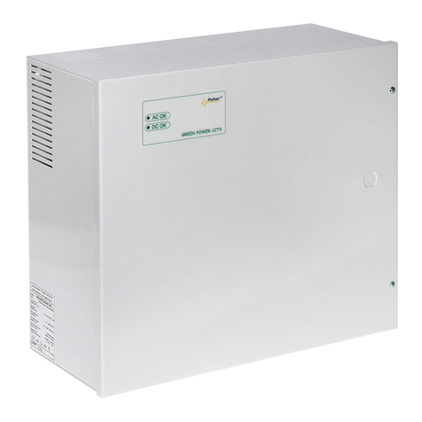
Pulsar PSD12080 manual

Pulsar

Pulsar PSD12080 manual

Pulsar PSDCSEP-12V4x1A user manual

Pulsar

Pulsar PSDCSEP-12V4x1A user manual

Moxa Technologies V2416A Series Quick installation guide

Moxa Technologies

Moxa Technologies V2416A Series Quick installation guide

alfatronix PV-USB1 Operating & assembly instructions

alfatronix

alfatronix PV-USB1 Operating & assembly instructions

Monster Power Reference PowerCenter HTS2600 owner's manual

Monster Power

Monster Power Reference PowerCenter HTS2600 owner's manual

Pulsar MSRK 2512 manual

Pulsar

Pulsar MSRK 2512 manual

Reno A&E RAE CPS-TS2E manual

Reno A&E

Reno A&E RAE CPS-TS2E manual

Aseko ASIN Salt 2 user manual

Aseko

Aseko ASIN Salt 2 user manual

Televes 563901 user manual

Televes

Televes 563901 user manual

Goobay DF 1730 LCD manual

Goobay

Goobay DF 1730 LCD manual

Venitem TUL 272 installation manual

Venitem

Venitem TUL 272 installation manual

Ultra Products ATX Power Supply user manual

Ultra Products

Ultra Products ATX Power Supply user manual

DRAKE PS151 quick guide

DRAKE

DRAKE PS151 quick guide

PowerBox Systems Mercury SRS instruction manual

PowerBox Systems

PowerBox Systems Mercury SRS instruction manual

Pulsar PS-12V3A manual

Pulsar

Pulsar PS-12V3A manual

Pulsar PSBS 5012D quick start guide

Pulsar

Pulsar PSBS 5012D quick start guide

Pentair HYDROMATIC A+ Installation and service manual

Pentair

Pentair HYDROMATIC A+ Installation and service manual

Pulsar HPSBOC 3524C quick start guide

Pulsar

Pulsar HPSBOC 3524C quick start guide

manuals.online logo
manuals.online logoBrands
  • About & Mission
  • Contact us
  • Privacy Policy
  • Terms and Conditions

Copyright 2025 Manuals.Online. All Rights Reserved.