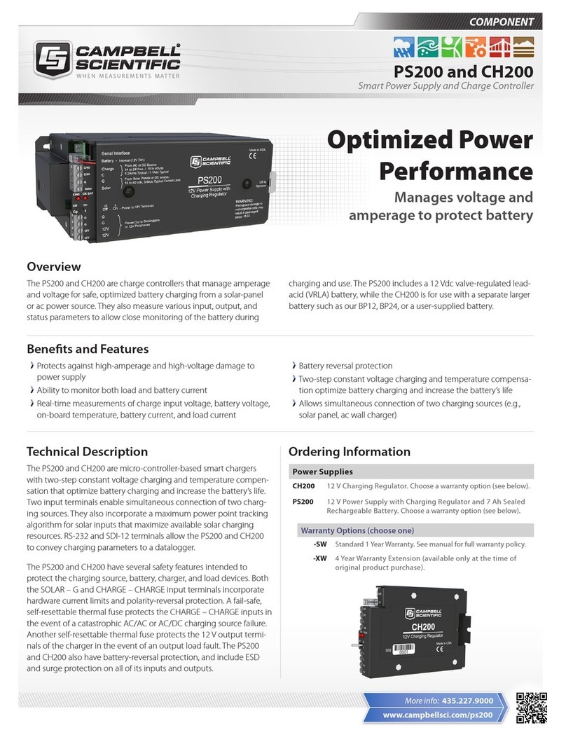
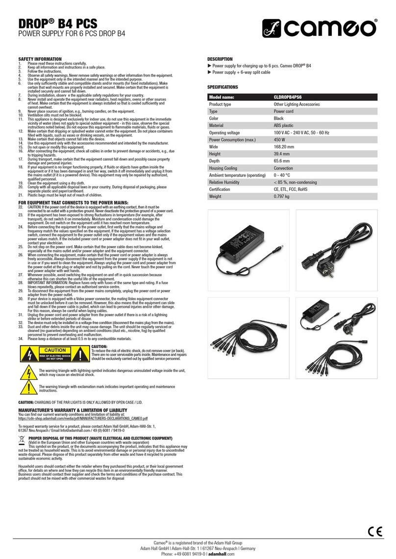
Advantech POC-IPSM90PS User manual

User Manual
POC-IPSM90PS
Point-of-Care Intelligent Power
System

POC-IPSM90PS User Manual ii
User Instructions
The document combines text and illustrations to provide a comprehensive overview
of the system. The information is presented as a sequential steps of actions, allowing
the user to learn directly how to use the device.
The text provides explanations and instructs the user step-by-step in the practical
use of the product, with short, clear instructions in an easy-to-follow sequence.
Definitions
Part No. 200890PS00 Edition 1
Printed in Taiwan December 2019
Warning! A WARNING statement provides important information about a poten-
tially hazardous situation that, if not avoided, could result in death or
serious injury.
Caution! A CAUTION statement provides important information about a poten-
tially hazardous situation that, if not avoided, may result in minor or
moderate injury to the user/patient or damage to the equipment or other
property.
Note! A NOTE provides additional information intended to avoid inconve-
nience during operation.

iii POC-IPSM90PS User Manual
Safety Instructions
1. Read these safety instructions carefully.
2. Retain this user manual for future reference.
3. Disconnect this equipment from any power outlet before cleaning. Use only a
damp cloth for cleaning. Do not use liquid or spray detergents.
4. For pluggable equipment, the power outlet socket must be located near the
equipment and easily accessible.
5. Protect this equipment from humidity.
6. Put this equipment on a reliable surface during installation. Dropping or letting it
fall may cause damage.
7. The openings on the enclosure are for air convection. Protect the equipment
from overheating. Do not cover the openings.
8. Ensure that the voltage of the power source is correct before connecting the
equipment to a power outlet.
9. Position the power cord away from high-traffic areas. Do not place anything over
the power cord.
10. All cautions and warnings on the equipment should be noted.
11. If the equipment is not used for a long time, disconnect it from the power source
to avoid damage from transient overvoltage.
12. Never pour any liquid into an opening. This may cause fire or electrical shock.
13. Never open the equipment. For safety reasons, the equipment should be
opened only by qualified service personnel.
14. If one of the following occurs, have the equipment checked by qualified service
personnel:
The power cord or plug is damaged.
Liquid has penetrated the equipment.
The equipment has been exposed to moisture.
The equipment is malfunctioning or does not operate according to the user
manual.
The equipment has been dropped and damaged.
15. Do not leave this equipment in an environment with a storage temperature of
below -10 °C (10 °F) or above 50 °C (122 °F). This could damage the equip-
ment. The equipment should be in a controlled environment.
16. Follow national, state, or local requirements to dispose of unit.
17. This equipment must not be used as a life-support system.
18. Grounding reliability can only be achieved when the equipment is connected to
an equivalent receptacle marked “hospital only” or “hospital grade”.
19. Use a power cord that matches the voltage of the power outlet, which has been
approved and complies with the safety standard of your particular country.
20. It is the responsibility of the end user to maintain the battery in a charged state.
The battery should not be left for more than 30 days without checking its charge
state. We recommend that a battery left in “storage state” should be charged
every 30 days to maintain the maximum life expectancy of the battery.
DISCLAIMER: These instructions are provided in accordance with the IEC 704-1
specifications. Advantech disclaims all responsibility for the accuracy of any state-
ments contained herein.

POC-IPSM90PS User Manual iv
Explanation of Graphical Symbols
Warning! 1. Input voltage rate: 100 ~ 240 VAC 19V/7.9A 150W
2. Output voltage rate: 12V/17V/19V/24V
Warning! 1. Do not modify this equipment without authorization from the manu-
facturer.
2. To avoid risk of electric shock, this equipment must only be con-
nected to a supply mains with protective earthing.
3. To prevent electric shock, turn off the power or unplug the power
cord before removing the cover.
4. To disconnect this product from the main power supply, disconnect
the plug from the socket. The power supply is regarded as
part of
this equipment.
5. Do not use the battery if the battery pack is damaged.
Caution! 1. Contact a qualified technician or your retail provider for battery
replacement. Do not attempt to do it yourself.
2. Batteries are at risk of exploding if incorrectly replaced. Replace
only with same or equivalent type as recommended by the manu-
facturer. Discard used batteries according to the manufacturer's
instructions.
IEC 60878 and ISO 3864-B.3.6: Warning: dangerous voltage
ISO 7000-0434: Caution, consult accompanying documents
IEC 60417 -5009: Standby
IEC 60417-5032: Alternating current
IEC 60417-5021: Equipotentiality
ISO 7010-M002: Follow instructions for use
IEC 60417-5021: Earth (ground)

v POC-IPSM90PS User Manual
Product Disposal
Within the European Union
FCC Class B
This equipment has been tested and found to comply with the limits for a Class B dig-
ital device, pursuant to Part 15 of the FCC rules.
These limits are designed to provide reasonable protection against harmful interfer-
ence when the equipment is operated in a residential environment. This equipment
generates, uses, and can radiate radio frequency energy, and if not installed and
used in accordance with the user manual, may cause harmful interference to radio
communications.
Note that even when this equipment is installed and used in accordance with the user
manual, there is still no guarantee that interference will not occur. If this equipment is
believed to be causing harmful interference to radio or television reception, this can
be determined by turning the equipment off and on again. If interference is occurring,
users are encouraged to try to correct the interference by one or more of the follow-
ing measures:
Reorient or relocate the receiving antenna
Increase the separation between the equipment and the receiver
Connect the equipment to a power outlet on a circuit different from that to which
the receiver is connected
Consult the dealer or an experienced radio/TV technician for help
EU-wide legislation, as implemented in each Member State,
requires that waste electrical and electronic products carrying the
mark (shown on the left) must be disposed of separately from nor-
mal household waste. This includes monitors and electrical acces-
sories, such as signal cables or power cords. To dispose of display
products, follow the guidance of your local authority, or ask the shop
where you purchased the product, or, if applicable, follow any
agreements made between yourself and the supplier.
This mark on electrical and electronic products only applies to cur-
rent European Union Member States.
Warning! Any changes or modifications made to the equipment that are not
expressly approved by the relevant standards authority could void your
authority to operate the equipment.

POC-IPSM90PS User Manual vi
Packing List
Before installation, ensure that the following items have been included with the prod-
uct:
1 x POC-IPSM90PS intelligent power system
1 x COM port cable
1 x DC-out cable
1 x 150W/19V adapter (optional)
Additional Information and Assistance
Contact your distributor, sales representative, or Advantech's customer service cen-
ter for technical support if you require additional assistance. Please have the follow-
ing information ready before calling:
Product name and serial number
Description of your peripheral attachments
Description of your software (operating system, version, application software,
etc.)
A comprehensive description of the problem
The exact wording of any error messages
Environmental Protection
Follow national requirements to dispose of unit.
Manufacturer
Advantech Co., Ltd.
No.1, Alley 20, Lane 26, Rueiguang Road, Neihu District, Taipei,
Taiwan 114, R.O.C.
TEL: (02) 2792-7818
Distributed in Europe by
Advantech Europe GmbH Kolberger Straße 7
D-40599 Düsseldorf, Germany
Tel: 49-211-97477350
Fax: 49-211-97477300
Visit the Advantech website at www.advantech.com or www.advantech.com.tw
should you require more information.
Warning! There are no user-serviceable parts inside the product. Refer all servic-
ing to qualified personnel. Only the accessories indicated on the list of
accessories above have been tested and approved to be used with the
device. Accordingly, we strongly recommend that only these accesso-
ries be used in conjunction with the device. Otherwise, the correct func-
tioning of the device may be compromised.
Note! This equipment is a source of electromagnetic waves. Before use,
ensure that there are no EMI-sensitive devices in the surrounding area
that may malfunction as a result.

vii POC-IPSM90PS User Manual
Contents
Chapter 1 General Information ............................1
1.1 Introduction ............................................................................................... 2
1.2 Specifications ............................................................................................ 2
Table 1.1: POC-IPSM90PS Intelligent Power System ................ 2
1.3 Dimensions ............................................................................................... 4
Chapter 2 System Setup.......................................7
2.1 Quick Tour................................................................................................. 8
2.1.1 Front view ..................................................................................... 8
Figure 2.1 POC-IPSM90PS Front View....................................... 8
2.1.2 Rear View ..................................................................................... 8
Figure 2.2 POC-IPSM90PS Rear View ....................................... 8
2.1.3 Underside View............................................................................. 8
Figure 2.3 POC-IPSM90PS Underside View............................... 8
2.1.4 Side View ...................................................................................... 9
Figure 2.4 POC-IPSM90PS Side View ........................................ 9
2.2 Power Input/Output Specifications ............................................................ 9
Table 2.1: DC-In/DC-Out Specifications...................................... 9
2.2.1 DC-IN Pin Definition.................................................................... 10
2.2.2 DC-Out Pin Definition.................................................................. 11
2.3 COM Output Specifications..................................................................... 11
2.3.1 COM Pin Definition ..................................................................... 12
2.4 Installation Procedures............................................................................ 12
Chapter 3 Battery Maintenance .........................17
3.1 Regular Use ............................................................................................ 18
Figure 3.1 Low-Battery Alert ...................................................... 18
3.2 Battery Storage ....................................................................................... 19
3.3 Troubleshooting ...................................................................................... 19
Chapter 4 Operating and Safety information....23
4.1 General Safety Guide.............................................................................. 24
4.2 Thermal Management ............................................................................. 24
4.3 Disconnect the Power ............................................................................. 24
4.4 Proper Handling ...................................................................................... 25
4.5 Battery Warnings..................................................................................... 25
4.6 Battery Safety Instructions ...................................................................... 26
4.7 Emergency Scenarios ............................................................................. 28
4.8 Battery Storage and Transportation ........................................................ 28
4.9 Battery Disposal ...................................................................................... 29
4.10 EMC Declaration ..................................................................................... 29

POC-IPSM90PS User Manual viii

Chapter 1
1General Information

POC-IPSM90PS User Manual 2
1.1 Introduction
Advantech’s POC-IPSM90PS is an intelligent power system designed to provide DC
power to various devices in a mobile environment. Based on a lithium-ion battery
(LIB), POC-IPSM90PS offers a greater battery capacity in a more lightweight design
compared to traditional battery pack systems (lead acid). LIB batteries are also safer
and more stable and clean than any other type of battery.
POC-IPSM90PS is suitable for installation in Advantech’s point-of-care terminals
used for medical applications or applications that necessitate a higher standard of
environmental safety.
1.2 Specifications
Table 1.1: POC-IPSM90PS Intelligent Power System
Power Adapter Power Input Voltage 100 ~ 240 VAC
Power Output 19V/7.89A, 150W
POC-IPSM90B
Battery Pack
Battery Pack Type 1 ~ 3 hot-swappable 3S3P/9 cells lithium-
ion battery
Battery Pack Capacity
90Wh each, total 270Wh
2 or 3 hot-swappable batteries support
6 ~ 12 hours operation (depending on
power consumption)
Battery Life Cycle Time 300 cycle time ≧70% normal capacity
Charge Time
Single battery pack
0~80%: ~ 90 mins @ (5A charge)
0~100%: ~ 150 mins
Three battery packs
0~80%: ~ 270 mins @ (5A charge, share
with three battery packs)
0~100%: ~ 330 mins
Normal Voltage 10.8V (3.6V/cell)
Normal Capacity 8400 mAh (2800 mAh/cell)
Cutoff Voltage of Discharge 9V
Max. Voltage of Charge 12.3V (4.1V/cell)
Max. Current of Discharge 10.05A
Max. Current of Charge 5.025A
Taper Current 0.45A
Pre-Charge Current 1A
Battery LED Indicator Battery indicator button with LED indicator
(five status)
Weight 0.5 kg/1.10 lb
Dimensions (W x D x H) 84.12 x 166.93 x 21.5 mm/3.31 x 6.57 x
0.84 in
POC-IPSM90PS
Intelligent Power
System
DC-Out Voltage 12V, 17V, 19V, 24V
(By DIP switch, adjustable)
Output Power Watts 90W rated output (default)
IP Rating IP54
I/O Ports
Communication Ports (IP54) RS-232: COM signal (M12 8-pin female)
DC-Out (IP54) 1 x DC-Out (M12 5-pin female)
DC-In (IP54) 1 x DC-In (M12 5-pin male)

3 POC-IPSM90PS User Manual
Chapter 1 General Information
Environmental
Charging Temperature 10 ~ 35 °C (50 ~ 95 °F)
Discharging Temperature 0 ~ 35 °C (32 ~ 95 °F)
Operating Temperature 0 ~ 35 °C (32 ~ 95 °F)
Storage Temperature -10 ~ 50 °C (14 ~ 122 °F)
OTP/Release Temp. of
Charge
60/55 °C (140/131 °F)
OTP = over-temperature protection of
battery pack
OTP/Release Temp. of Dis-
charge
70/60 °C (158/140 °F)
OTP = over-temperature protection of
battery pack
Transportation Temperature
(POC-IPSM90PS) -20 ~ 50 °C (-4 ~ 122 °F)
Transportation Pressure
(POC-IPSM90PS) 700 ~ 1013 hPa
Transportation Humidity
(POC-IPSM90PS) 45 ~ 85% (non-condensing)
Warranty Warranty
Electronic and mechanical parts: 2 years
Battery pack: capacity 70%, 300 cycles or 1
year (depending on which occurs first)
Weight Weight < 4 kg/8.81 lb
(POC-IPSM90PS with three battery packs)
Dimensions Dimensions (W x D x H) 563.8 x 125 x 76.5 mm/22.19 x 4.92 x 3.01
in
Certification Certification
Power system: IEC60601-1-2, fourth edi-
tion, and IEC60601-1
Charging station: IEC62368
Battery pack: UN38.3, UL2054, IEC62133
Note! 1. “Battery life cycle” refers to the count number of complete charge/
discharge cycles that the battery is able to support before its
capacity drops below 70% of the original capacity.
2. “Battery life” refer to the amount of time the battery can support
device operation before needing to be recharged.
3. One “battery cycle count” is defined as one full battery discharge
and charge cycle.
4. LED Indicators
One Battery Status indicator
Five Battery Capacity indicators
5 x Green indicators = 80 ~ 100% capacity
4 x Green indicators = 60 ~ 80% capacity
3 x Green indicators = 40 ~ 60% capacity
2 x Green indicators = 20 ~ 40% capacity
1 x Green indicator = 0 ~ 20% capacity

POC-IPSM90PS User Manual 4
1.3 Dimensions
The system dimensions are 563.5 x 125 x 76.5 mm/22.18 x 5.52 x 3.01 in.
(Unit: mm)

5 POC-IPSM90PS User Manual
Chapter 1 General Information

POC-IPSM90PS User Manual 6

Chapter 2
2System Setup

POC-IPSM90PS User Manual 8
2.1 Quick Tour
Before setting up the POC-IPSM90PS intelligent power system, take a moment to
familiarize yourself with the various functions of the system connectors, switches,
and ports (which are shown below).
2.1.1 Front view
Figure 2.1 POC-IPSM90PS Front View
2.1.2 Rear View
Figure 2.2 POC-IPSM90PS Rear View
2.1.3 Underside View
(1) DC-In
(2) DC-Out
(3) COM
Figure 2.3 POC-IPSM90PS Underside View
VESA mount holes
(1) (2) (3)

9 POC-IPSM90PS User Manual
Chapter 2 System Setup
2.1.4 Side View
Figure 2.4 POC-IPSM90PS Side View
2.2 Power Input/Output Specifications
Power On/Off
button
Battery slot
VOUT Voltage
setting switch
Battery slot
Table 2.1: DC-In/DC-Out Specifications
Min Max Note
DC-In 15V 25V Rating: 19V input
Adapter: Delta MDS-150AAS19 BJ (19V/150W)
DC-Out According to switch
settings
12V/17V/19V/24V
Factory shipping default: 12V (see Note 2 below)
Output power: 90W max.
Note! The DC-In voltage is a wide range input. If this is unnecessary, use a
standard 19V adapter to power the device.
Note! DC-Out Switch Setting Table
For the POC-W2x3 series, set this to 19V VOUT voltage.
SW.1 SW.2 VOUT
Switch
OFF OFF 12V (default)
OFF ON 17V
ON OFF 19V (for POC-W2xx series)
ON ON 24V

POC-IPSM90PS User Manual 10
The following SW1 settings are printed on the enclosure cover for users to reference
before adjustment.
The 19V output setting is as shown below.
2.2.1 DC-IN Pin Definition
DC-In uses Amphenol A00-MSAS-05PMR-SF703 (male pin type).
Pin Number Function Note
1 Return/GND
2 Return/GND
3 DC In
4 DC In
5 DC In
Sleeve/Ring Return/GND

11 POC-IPSM90PS User Manual
Chapter 2 System Setup
2.2.2 DC-Out Pin Definition
DC-Out uses Amphenol A00-MSAS-05PFR-SF703 (female hole type).
2.3 COM Output Specifications
Note! Confirm the “key” direction to identify pin 1.
Pin Number Function Note
1 Return/GND
2 Return/GND
3 DC Out
4 DC Out
5 DC Out
Sleeve/Ring Return/GND
Note! Confirm the “key” direction to identify pin 1.

POC-IPSM90PS User Manual 12
2.3.1 COM Pin Definition
COM uses Amphenol A00-MSAS-08PFR-SF703 (female hole type).
2.4 Installation Procedures
Before installing the POC-IPSM90PS power system onto a POC terminal or using
POC-IPSM90PS to supply power, perform a complete battery charge. Next follow the
steps below to install and setup the system.
Step 1: Remove the AC power cord and battery packs.
Step2: Configure the DC output voltage via the switch.
Pin Number Function Note
1GND
2GND
3GND
4 Reserved Remove USB
5 Reserved Remove USB
6 Reserved Remove USB
7 RX Please connect to Host TX (RS232 level)
8 TX Please connect to Host RX (RS232 level)
Sleeve/Ring GND
Note! Confirm the “key” direction to identify pin 1.
SW.1 SW.2 VOUT
Switch
OFF OFF 12V (default)
OFF ON 17V
ON OFF 19V (for POC-W2xx series)
ON ON 24V
Table of contents
Other Advantech Power Supply manuals
Popular Power Supply manuals by other brands

Thermal Dynamics
Thermal Dynamics PakMaster XLPLUS 50 Service manual

JFA Electronicos
JFA Electronicos BOB STORM instruction manual
Pulsar
Pulsar PSP24010 quick start guide
BEL
BEL LDN85 Series Installation instruction
BEL
BEL LDC240 Seriesl LDC240-12 installation instructions
Festo
Festo EduTrainer 571812 operating instructions
