Advantech LNC M5800 Series User manual

A-LNC Milling
Machine Series
Operation Manual
Leading Numerical Controller
Version: V01.00.003(4408230007)
Advantech-LNC Technology Co., Ltd.

Milling Machine Series
Table of Contents
IAdvantech-LNC Technology Co., Ltd.
Table of Contents
_Toc448762604
1CNC operations .............................................................................................1
1.1 Type of operation device........................................................................................................................ 1
1.1.1 M5800 series............................................................................................................................ 1
1.1.2 M6800 series............................................................................................................................ 8
1.2 Screen and function instructions........................................................................................................... 13
1.3 Monitoring group (MONITOR) .............................................................................................................. 15
1.3.1 Monitoring ............................................................................................................................ 15
1.3.2 Coordinate switching.............................................................................................................. 21
1.3.3 Variables................................................................................................................................ 24
1.3.4 Machining settings ................................................................................................................. 26
1.3.5 Machining data ...................................................................................................................... 29
1.3.6 Relative coordinates............................................................................................................... 30
1.3.7 Wear ..................................................................................................................................... 31
1.3.8 MDI ....................................................................................................................................... 32
1.3.9 Figures................................................................................................................................... 33
1.3.10 Load ...................................................................................................................................... 34
1.3.11 Program restart...................................................................................................................... 35
1.4 Program group (PROG)......................................................................................................................... 39
1.4.1 Select a file to be opened ....................................................................................................... 39
1.4.2 Preview ................................................................................................................................. 42
1.4.3 Supplementary commands ..................................................................................................... 43
1.4.4 Program editing ..................................................................................................................... 44
1.4.5 File management ................................................................................................................... 45
1.4.6 Manufacturer macros............................................................................................................. 49
1.4.7 Plot settings........................................................................................................................... 54
1.5 Compensation group (OFFSET) ............................................................................................................. 56
1.5.1 Coordinate system ................................................................................................................. 56
1.5.2Tool management .................................................................................................................. 61
1.5.3 Tool service life ...................................................................................................................... 64
1.5.4 Wear management................................................................................................................. 65
1.5.5 Tool registration ..................................................................................................................... 66
1.5.6 Automatic tool alignment ....................................................................................................... 67
1.6 Diagnosis group (DGNOS)..................................................................................................................... 72

Milling Machine Series
Table of Contents
II Advantech-LNC Technology Co., Ltd.
1.6.1 Alerts and warnings ............................................................................................................... 72
1.6.2 Ladder diagram ...................................................................................................................... 74
1.6.3 IOCSA .................................................................................................................................... 75
1.6.4 Timer/counter........................................................................................................................ 76
1.6.5 System information ................................................................................................................ 77
1.6.6 Alert history........................................................................................................................... 78
1.6.7 Operation history................................................................................................................... 79
1.6.8 R value .................................................................................................................................. 80
1.6.9 Waveform monitoring ............................................................................................................ 81
1.7 Maintenance group (MAINTE) .............................................................................................................. 82
1.7.1 User parameters .................................................................................................................... 82
1.7.2 Language settings................................................................................................................... 83
1.7.3 Network settings.................................................................................................................... 84
1.7.4 Changing identity ................................................................................................................... 85
1.7.5 Hardware contact................................................................................................................... 86
1.7.6 Parameters ............................................................................................................................ 87
1.7.7 Backup .................................................................................................................................. 88
1.7.8 System update ....................................................................................................................... 90
1.7.9 Tuning functions .................................................................................................................... 91
1.7.10 Period of use.......................................................................................................................... 94
1.7.11 Page permissions ................................................................................................................... 96
1.7.12 Change password ................................................................................................................... 97
1.7.13 Date and time ........................................................................................................................ 98
1.7.14 Version information ............................................................................................................... 99
1.7.15 Project settings .................................................................................................................... 100
1.8 Usage instructions ............................................................................................................................. 101
1.8.1Opening and editing a file..................................................................................................... 101
1.8.2 Execute machining ............................................................................................................... 109
1.8.3 Using the MDI function .........................................................................................................111
1.8.4 Program restart.....................................................................................................................113
1.8.5 Automatic tool alignment ......................................................................................................116
1.8.6 Network settings and connections ........................................................................................ 124
1.8.7 System update ..................................................................................................................... 127
1.8.8 System data backup - export................................................................................................. 131
1.8.9 System data backup - import ................................................................................................ 135
1.8.10 Preview function.................................................................................................................. 139
1.8.11 Editing and using manufacturer macros................................................................................. 145

Milling Machine Series
Table of Contents
IIIAdvantech-LNC Technology Co., Ltd.
1.8.12 Tool offset settings ............................................................................................................... 148
1.8.13 Coordinate system settings ................................................................................................... 150
1.8.14 Parameter settings ............................................................................................................... 153
1.8.15 File backup - import ............................................................................................................. 158
1.8.16 File backup - export.............................................................................................................. 163
1.8.17 Waveform monitoring function............................................................................................. 167
1.8.18 OnLine Help ......................................................................................................................... 174
1.8.19 Switching multiple paths ...................................................................................................... 174
2Control panel operations ........................................................................... 176
2.1 Operating panel ................................................................................................................................ 176
2.1.1 M5800 series........................................................................................................................ 176
2.1.2 M6800 series........................................................................................................................ 176
2.2 LED signal light (LED SIGNAL) .............................................................................................................. 177
2.3 Axis selection (AXIS SELECTION).......................................................................................................... 178
2.4 Mode selection (MODE SELECTION) .................................................................................................... 179
2.5 Spindle operation & spindle speed adjustment .................................................................................... 182
2.6 Supplementary function keys ............................................................................................................. 182
2.7 Emergency stop (EMG-STOP).............................................................................................................. 189
2.8 Program start (CYCLE START) & program pause (FEED HOLD) ................................................................ 190
2.9 Feed rate adjustment......................................................................................................................... 191
2.10 Program protection lock..................................................................................................................... 191
2.11 Seven-segment display of tool number ............................................................................................... 192
2.12 Power on/off..................................................................................................................................... 192


Milling Machine Series
CNC operations
1
Advantech-LNC Technology Co., Ltd.
1CNC operations
1.1 Type of operation device
The operation panel can be divided into the LCD liquid crystal display, MDI data input panel, and OP operation panel. The
main function of the MDI data input panel is to allow users to edit or modify a program and set numerical values. The OP
operation panel is a control panel for meeting all machining requirements; it is equipped with various switches and
function keys, and a pulse generator (hand wheel), etc. The operation panel can have different designs based on different
machines, but this system contains a set of standard panels which can be selected by the machine manufacturer.
1.1.1 M5800 series
Keys shown on the LCD liquid crystal display:
Function keys: There are 10 horizontal keys right below the LCD. They allow users to select functions which are
shown in the lower part of the screen.

Milling Machine Series
CNC operations
2
Advantech-LNC Technology Co., Ltd.
LCD liquid crystal display
Function keys

Milling Machine Series
CNC operations
3
Advantech-LNC Technology Co., Ltd.
Keys shown on the MDI panel:
MDI data input panel
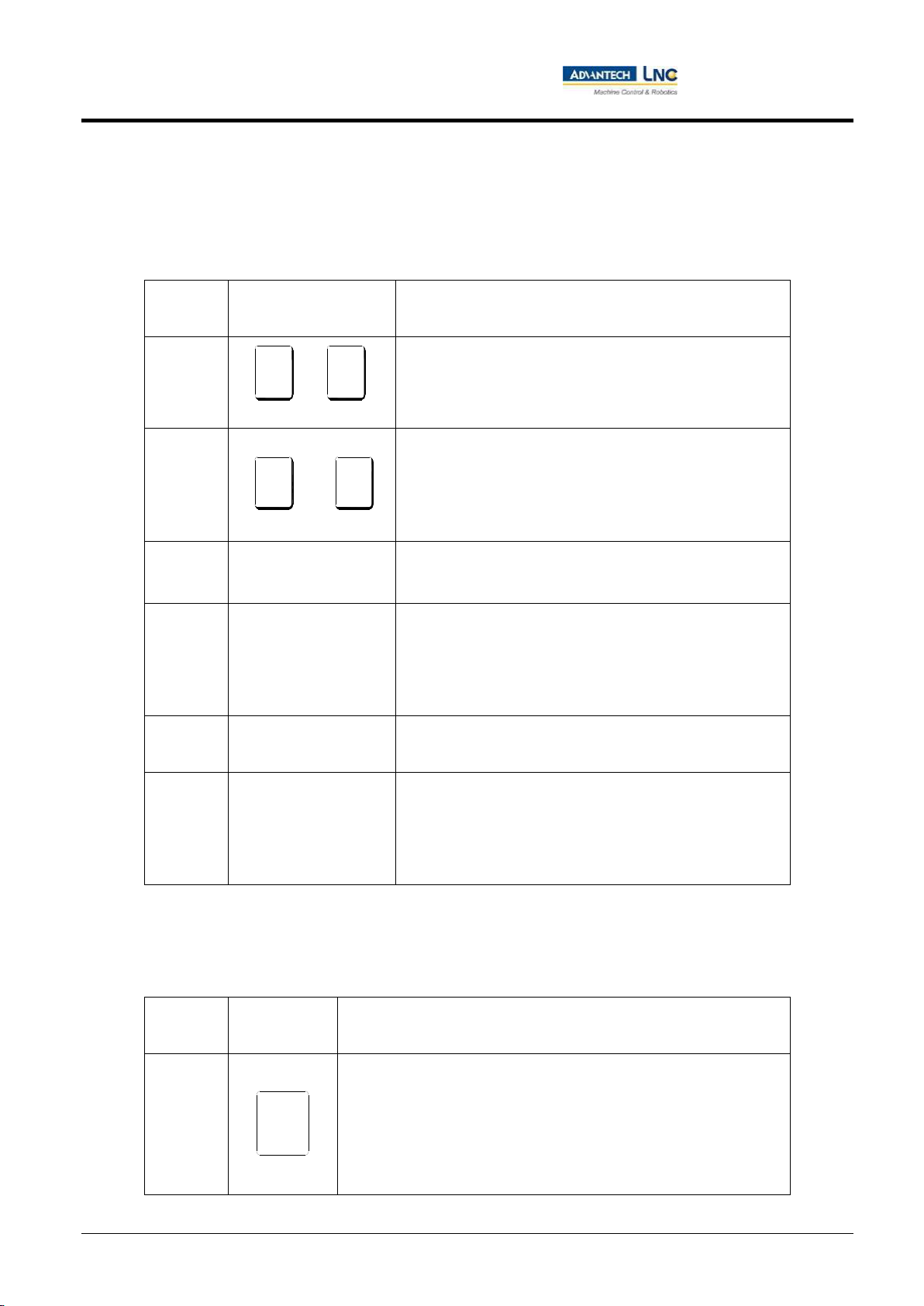
A. CNC function group key:
Name
Function group
key
Description
Monitoring
group
The group of screens showing various coordinates and machining data.
Program
group
All screens related to program information (in coordination with 1.
Editing mode, 2. Memory mode, 3. Manual mode).
Compensation
group
Sets the tool offset.
Diagnosis
group
Shows real time information from the diagnosis screen.

Milling Machine Series
CNC operations
4
Advantech-LNC Technology Co., Ltd.
Name
Function group
key
Description
Maintenance
group
System related settings.
Milling Machine Series
CNC operations
5
Advantech-LNC Technology Co., Ltd.
B. Text symbol and numerical symbol keys:
These letters, symbols, and digits are used mainly for program editing and data input. Some of the symbols are
minimized below the keys. The SHIFT key and the text symbol key must be pressed simultaneously to use these
minimized symbols.
Name
Supplementary editing
keys
Description
Letter
~
There are 26 letter keys from A to Z which can be used for
location or argument commands.
Number
?
9
0
=
~
?
9
0
=
There are 10 number keys from 0 to 9 which can be used for
numerical values or input data.
Symbol
/
The section requiring diagonal jump during program editing
Symbol
;
1. Pressing this key during program editing will indicate the
end of input program section.
2. If this key is placed at the very beginning of a program
block, it means this block of code will not be executed.
Symbol
﹒
The numerical value needs to be separated by a decimal point
during program editing.
Symbol
(、)、<、>、,、: 、
&、*、?、[、]、$、%、
^、!、@、#、+、=、-、
_、
Symbols to be used during program editing.
C. Supplementary editing keys:
These keys can be used in coordination with cursor and the highlighted row on the screen for program
modification, data setting, and page switching.
Name
Supplementary
editing keys
Description
System
reset
1. Default values of system rest status.
2. Cancel alert after the abnormal situation has been cleared.
3. Cancel the machining process after cycle start.
4. Return the cursor to highlight the program header in editing
mode.
X
U
Z
W
Reset
/ /
/ /
Reset
/ /
/ /

Milling Machine Series
CNC operations
6
Advantech-LNC Technology Co., Ltd.
Name
Supplementary
editing keys
Description
Go to
previous
page
<Page Up>
Field on the screen for navigating to the previous page.
Go to next
page
<Page Down>
Field on the screen for navigating to the next page.
Input
<Enter>
1. After entering a numerical value in the input area, press <Enter> to
store the numerical value into the field.
2. In windows explorer, move the cursor to the program location and
press <Enter> to open the file.
3. Press <Enter> in editing mode to insert a blank line.
Moves the
cursor up
1. Moves the cursor up while in program editing status.
2. Moves the cursor on this page upward.
Moves the
cursor down
1. Moves the cursor down in program editing status.
2. Moves the cursor on this page down.
Moves the
cursor left
1. Moves the cursor to the left in program editing status.
2. Moves the cursor on this page to the left.
Moves the
cursor right
1. Moves the cursor to the right in program editing status.
2. Moves the cursor on this page to the right.
Whitespace
Space
Enter the whitespace character.
Character
shift
Shift
It can be used for entering special symbols in combination with
symbol/number keys.
Please note: Character shift can only be done by simultaneously
pressing the SHIFT key and the text symbol key.
Row header
position
Home
Return the cursor for highlighted row to the character position at row
header during program editing.

Milling Machine Series
CNC operations
7
Advantech-LNC Technology Co., Ltd.
Name
Supplementary
editing keys
Description
End of row
position
End
Return the cursor to the last character position of the selected row
during program editing.
Please note: it must be used in combination with SHIFT key.
Cancel
character
CAN
Cancels the unwanted character at previous position.

Milling Machine Series
CNC operations
8
Advantech-LNC Technology Co., Ltd.
1.1.2 M6800 series
Keys shown on the LCD liquid crystal display:
Function keys: There are 12 horizontal keys right below the LCD. They allow users to select functions which are
shown in the lower part of the screen.

Milling Machine Series
CNC operations
9
Advantech-LNC Technology Co., Ltd.
LCD liquid crystal display
Function keys

Milling Machine Series
CNC operations
10
Advantech-LNC Technology Co., Ltd.
Keys shown on the MDI panel:
A. CNC function group keys:
Name
Function group
key
Description
Monitoring
group
The group of screens showing various coordinates and machining data.
Program
group
All screens related to program information (in coordination with 1.
Editing mode, 2. Memory mode, 3. Manual mode).
Compensation
group
Sets the tool offset.
Diagnosis
group
Shows real time information from the diagnosis screen.
Maintenance
group
System related settings.
CNC function group key

Milling Machine Series
CNC operations
11
Advantech-LNC Technology Co., Ltd.
B. Text symbol and numerical symbol keys:
These letters, symbols, and digits are used mainly for program editing and data input. Some of the symbols are
minimized below the keys. The SHIFT key and the text symbol key must be pressed simultaneously to use these
minimized symbols.
C. Supplementary editing keys:
These keys can be used in coordination with cursor and the highlighted row on the screen for program
modification, data setting, and page switching.
Name
Supplementary
editing key
Description
System
reset
1. Default values of system rest status.
2. Cancel alert after the abnormal situation has been cleared.
3. Cancel the machining process after cycle start.
4. Return the cursor to highlight the program header in editing
mode.
Go to
previous
page
( PgUp )
1. Field on the screen for navigating to the previous page.
Go to next
page
( PgDn )
1. Field on the screen for navigating to the next page.
Letter/symbol keys
Number/symbol
keys

Milling Machine Series
CNC operations
12
Advantech-LNC Technology Co., Ltd.
Name
Supplementary
editing key
Description
Input
1. After entering a numerical value in the input area, press <Enter> to
store the numerical value in the field.
2. After selecting a key in the child window, press <Enter> to confirm.
3. Press <Enter> in editing mode to insert a blank line.
Moves the
cursor up
1. Moves the cursor up while in program editing status.
2. Moves the cursor on this page upward.
Moves the
cursor down
1. Moves the cursor down in program editing status.
2. Moves the cursor on this page down.
Moves the
cursor left
1. Moves the cursor to the left in program editing status.
2. Moves the cursor on this page to the left.
Moves the
cursor right
1. Moves the cursor to the right in program editing status.
2. Moves the cursor on this page to the right.
Deletes the
character
1. Deletes the unwanted character at the next position.
Whitespace
1. Enter the whitespace character.
Character
shift
1. It can be used for entering special symbols in combination with
symbol/number keys.
Please note: Character shift can only be done by simultaneously
pressing the SHIFT key and the text symbol key.
Row header
position
1. Return the cursor for highlighted row to the character position at
row header during program editing.
End of row
position
1. Return the cursor to the last character position of the selected row
during program editing.

Milling Machine Series
CNC operations
13
Advantech-LNC Technology Co., Ltd.
1.2 Screen and function instructions
This controller can be divided into 5 function groups: Monitoring (MONITOR), program (PROG), offset (OFFSET), diagnosis
(DIAGN), and maintenance (MAINTE). In this manual, 【】represents function keys in the lower part of screen, and <
> represents keys on the MDI panel.
Layout of the display screen:
Note: Different models are equipped with different numbers of function keys in the lower part of screen.
1
2
3
4
5
6
7
8
9
10
11
12

Milling Machine Series
CNC operations
14
Advantech-LNC Technology Co., Ltd.
1: Path information. (It will only be shown when the multi-path function is available)
Note: numerator is the current path number, and denominator is the total number of paths.
2 : Name of currently assigned program.
Note: it refers to the filename currently being used by the controller.
3 : CNC mode information.
Note: 1. Jog, 2. Reference point, 3. Manual, 4. Incremental, 5. Hand wheel, 6. Automatic
4 : Machine's status information.
Note: 1. Not ready, 2. Ready, 3. Cycle start, 4. Machine paused, 5. Section stopped.
5 : Current function group.
Note: 1. Monitoring, 2. Program, 3. Offset, 4. Diagnosis, 5. Maintenance.
6 : Name of current page.
Note: it refers to the function page currently accessed by the controller.
7 : System time and user level.
Note: it refers to the current user level between L1 to L7.
8 : Range of each screen's display area.
Note: the range of variation to be shown by switching among function pages of each group.
9 : Input area/section.
Note: provided by the controller for users to input values in various fields on each page.
10: Summary information reminder section.
Note: the controller will provide an operation information summary prompt to remind users.
11: Display areas corresponding to the keys on the screen.
Note: this area is to be used for corresponding keys on the screen. If there are keys listed in this manual but they
cannot be seen on the controller, it means that current user does not have the proper permission level.
12: Error messages.
Note: Alerts and warnings.

Milling Machine Series
CNC operations
15
Advantech-LNC Technology Co., Ltd.
1.3 Monitoring group (MONITOR)
1.3.1 Monitoring
On the monitoring page, users can view various information such as the filename of the current program,
current operating mode, current machine status, has an alert being issued, feeding % status, spindle % status,
number of workpieces undergoing the machining process, maximum number of machining pieces, time required
for single machining, total time of machining accumulated, and various coordinates.
Description of various fields:
Users can inspect the current machining program's filename on the monitoring page as shown in the figure
below.
This manual suits for next models
1
Table of contents
Other Advantech Power Tools manuals

Popular Power Tools manuals by other brands

Bosch
Bosch GST Professional Series Original instructions

Metabo
Metabo STE 100 PLUS - operating instructions

Zimmer
Zimmer LKE Series Installation and operating instructions

Fein
Fein ASg 636 Kinetik operating instructions

Tyco Electronics
Tyco Electronics PRO-CRIMPER III instruction sheet

Josef Kihlberg
Josef Kihlberg B561PN Repair instructions


