INDUSTRIAS TECHNOFLEX MAMUT-10 User manual
http://www.technoflex.es/
BANDEJA VIBRANTE “MAMUT-10”
PLATE COMPACTOR “MAMUT-10”
COMPACTADORA DE PLACAS “MAMUT-10”
MAQUINARIA PARA LA CONSTRUCCIÓN Y OBRAS PÚBLICAS
BUILDING AND PUBLIC WORKS MACHINERY
MÁQUINAS PARA A CONSTRUÇÃO E OBRAS PUBLICAS

Este manual está compuesto por los siguientes capítulos:
This manual is divided into the sections listed below:
Este manual está composto dos seguintes capítulos:
Utilización (Español)
Operation (English)
Utilização (Português)
Este manual contiene información y procedimientos que son necesarios
para utilizar y mantener esta máquina. Para su propia seguridad y
protección, por favor lea cuidadosamente, entienda y observe todas las
instrucciones de seguridad descritas en este manual. LOS DATOS
CONTENIDOS EN ESTE MANUAL SON CORRECTOS EN EL MOMENTO
DE SU EDICIÓN. NO OBSTANTE EL FABRICANTE SE RESERVA EL
DERECHO DE MODIFICAR LAS CARACTERÍSTICAS, SIN PREVIO
AVISO A FAVOR DEL COMPROMISO DE MEJORA CONTINUA.
This manual provides information and procedures to safely operate and
maintain this machine. For your own safety and protection from injury,
carefully read, understand and observe the safety instructions described
in this manual. THE INFORMATION CONTAINED IN THIS MANUAL ARE
CORRECT FROM THE MOMENT OF EDITING. HOWEVER THE
MANUFACTURER RESERVES THE RIGHT TO MODIFY THE
CHARACTERISTICS, WITHOUT PRIOR NOTICE IN CONSIDERATION
OF CONTRACT COMMITMENT OF CONTINUOUS IMPROVEMENT.
Este manual contém informação e procedimentos que são necessários para utilizar e
manter esta máquina. Para a sua própria seguridade e protecção, faça o favor de ler
com cuidado, entender e observar todas as instruções de seguridade descritas neste
manual. OS DATOS QUE ESTE MANUAL CONTÉM SÃO CORRECTOS NO
MOMENTO DA SUA EDIÇÃO. MAS O FABRICANTE RESERVA-SE O DIREITO DE
MODIFICAR AS CARACTERÍSTICAS SEM ANTES AVISAR, A FAVOR DO
COMPROMISSO DA MELHORA CONTÍNUA.

1
Mantenga este manual ó una copia de él con la máquina. Si se
pierde ó Vd. desea un ejemplar adicional haga el favor de
comunicarse con INDUSTRIAS TECHNOFLEX S.A. Esta máquina
fue fabricada con la seguridad del usuario en mente; sin
embargo, situaciones peligrosas pueden presentarse si la
máquina es utilizada inapropiadamente. Siga las instrucciones
de utilización cuidadosamente. Si Vd. tiene preguntas ó dudas
acerca de la utilización o mantenimiento de este equipo, haga el
favor de comunicarse con INDUSTRIAS TECHNOFLEX S.A.
Keep this manual or a copy of it with the machine. If you lose
this manual or need an additional copy, please contact
INDUSTRIAS TECHNOFLEX S.A. This machine is built with user
safety in mind, however, it can present hazards if improperly
operated and serviced. Follow operating instructions carefully!
If you have questions about operating or servicing this
equipment, please contact INDUSTRIAS TECHNOFLEX S.A.
Mantenha este manual ou uma cópia dele com a máquina. Se o perder ou se
o senhor desejar um exemplar adicional faça o favor de se comunicar com
INDÚSTRIAS TECHNOFLEX S.A. Esta máquina foi fabricada pensando na
seguridade do usuário; mas se a máquina for utilizada impropriamente
poderiam se apresentar em situações perigosas. Siga as instruções de
utilização cuidadosamente. Se o senhor tiver perguntas ou dúvidas sobre a
utilização ou mantimento de este equipe, faça o favor de se comunicar com
INDÚSTRIAS TECHNOFLEX S.A.

2
ÍNDICE
Capítulo Página
1.- INTRODUCCIÓN ___________________________ 3
2.- AP ICACIONES ____________________________ 3
3.- CONTRO ES Y FUNCIONES _________________ 3
4.- RIESGOS Y PE IGROS ______________________ 3
5.- OPERACIONES _____________________________ 4
6.- MANTENIMIENTO PREVENTIVO ____________ 5
7.- SERVICIOS _________________________________ 7
8.- ESPECIFICACIONES ________________________ 7
9.- GARANTÍA _________________________________ 8
10.- POSIB ES FA OS __________________________ 8
11.- POSIB ES FA OS DE MOTOR ______________ 9
12.- REPUESTOS ________________________________ 10-13

3
1.- INTRODUCCIÓN
Gracias por escoger este equipo. Hemos tenido un especial cuidado con su diseño, fabricación y
posterior prueba. La garant a de este equipo está cubierta para seis meses. Las posibles
reparaciones o repuestos que se necesiten, las puede conseguir por medio de esta empresa o por
su agente o proveedor.
INSTRUCCIONES PARA EL FUNCIONAMIENTO GENERAL DEL EQUIPO
La meta de nuestra compañ a es fabricar un equipo en que el operario pueda trabajar con él, de
una manera eficiente y correcta. Lo más importante para este equipo o cualquier herramienta es
el operario. La prevención, es la mejor protección contra accidentes. No podemos incluir todos
los posibles accidentes, pero les proporcionamos un resumen de los más frecuentes, el operario
debe ir con cuidado con los posibles riesgos en el lugar de trabajo. El operario debe leer el
manual y entenderlo antes de comenzar a trabajar con el equipo.
Aprenda a utilizar los equipos de trabajo. Si usted a utilizado previamente un equipo similar ,
tenga cuidado en probar el nuevo equipo en un lugar adecuado antes de empezar a usarlo.
Consiga conocer las capacidades, limitaciones, riesgos, y funciones principales del equipo y
como detenerlo en cualquier situación.
2.- AP ICACIONES
Compactación de zanjas
Mantenimiento de caminos
Recubrimientos
Trabajo de tierra
Carreteras
3.- CONTRO ES Y FUNCIONES
El motor se controla por medio del interruptor ON/OFF situado debajo del depósito de
combustible.
La tensión de la correa de accionamiento es ajustable, afloje las tuercas de los tornillos, para
poder asegurar el motor a la base. Ajuste los tornillos fijos , que van contra el motor para
conseguir la tensión adecuada. Asegúrese que los tornillos y tuercas, están bien fijados después
del ajuste.
4.- RIESGOS Y PE IGROS
Nunca permita que una persona trabaje con la máquina sin la formación adecuada.
Asegúrese que los operarios han le do y entendido las instrucciones de la máquina.
El uso impropio o descuidado de la máquina puede acarrear lesiones serias.
Estas máquinas son pesadas, y deben posicionarse por medio de dos personas de fuerza
apropiada. Usen las barras alzadoras que vienen en la máquina, y util cenlas de forma adecuada.
RIESGOS MECÁNICOS
NO trabajar con la máquina sin los equipos de protección adecuados.
PROTEJA manos y dedos de posibles lesiones por objetos móviles de la máquina.
ASEGÚRESE que el motor está en posición OFF.
ASEGÚRESE que tanto el operario como la máquina trabajen en un lugar plano, sin riesgos de
ca das.
NO deje la máquina en funcionamiento, mientras esté desatendida.

4
ASEGÚRESE antes de compactar, que los muros de la zona a compactar, son estables y no hay
posibilidad de derrumbe
ASEGÚRESE de que el área a compactar, no contiene cables eléctricos, de gas, agua o de
comunicaciones, ya que pueden producirse daños a causa de la vibración.
NUNCA esté encima de la máquina mientras trabaje.
NO SOBREPASE el número de revoluciones del motor en 3500 r.p.m. Puede provocar
accidentes en el operario y destrozos en la máquina.
TENER CUIDADO con tocar las partes colindantes al motor cuando esté caliente, ya que se
puede sufrir quemaduras.
ASEGÚRESE que las reparaciones del motor o de la máquina, las realizan personal
COMPETENTE.
¡RIESGOS DE FUEGO Y EXPLOSIÓN¡
La GASOLINA es extremadamente inflamable y explosiva según las condiciones.
ASEGÚRESE de que la gasolina sólo esté almacenada en lugares apropiados.
No repostar, cuando el motor esté en funcionamiento o caliente.
NO repostar de gasolina el motor cerca de chispas o una persona que esté fumando.
NO llenar el depósito a rebosar de combustible, ya que derramar el combustible puede acarrear
riesgos, si se derrama , asegurarse de haber limpiado el depósito antes de encender el motor.
ASEGURARSE de que el depósito de gasolina esté bien cerrado después de repostar.
¡RIESGOS QUÍMICOS¡
NO repostar en lugares que no estén suficientemente ventilados.
EL MONÓXIDO DE CARBONO producido por la combustión del motor, puede acarrear la
muerte en lugares cerrados.
¡RIESGOS DE RUIDO¡
EXCESIVO RUIDO puede producir sordera temporal o permanente.
UTILIZAR las protecciones contra el ruido necesarias para evitar grandes exposiciones al ruido.
ROPA DE PROTECCIÓN
SIEMPRE se tienen que utilizar los equipos de protección adecuada , en el lugar de trabajo.
UTILIZAR protección para los ojos, y máscara para ambientes polvorientos. Se debe utilizar
botas de seguridad para este tipo de trabajo.
¡RIESGOS ADICIONALES¡
Ca das, resbalones, son las mayores causas de accidente. Tenga cuidado con las superficies de
trabajo irregulares, o resbaladizas.
Hay que tener un especial cuidado cuando se trabaje en excavaciones o agujeros sin protección.
5.- OPERACIONES
La máquina satisface las necesidades de compactación de materiales granulares y bituminosos,
(arcilla, tierras granulares), usando la fuerza óptima producida por la bandeja vibrante.
El lugar de trabajo, ha de nivelarse antes de comenzar la compactación.
Para la consolidación del suelo , es vital una humedad correcta, para ello nos ayudamos de una
manguera de agua o lubricante. Una humedad no adecuada debilitará la tierra , y nos llevará a
realizar un proceso de compactación inadecuado. Poca humedad provoca la compactación
inadecuada, mientras que nivel alto de humedad debilita la tierra, y provoca que la máquina no
avance de manera correcta.
El kit opcional del tanque de agua está recomendado cuando la máquina trabaje en superficies
bituminosas y la pantalla de agua evita la acumulación de material debajo de la base.
Usar gasolina sin plomo, para respetar el medioambiente.
El propio movimiento vibratorio de la máquina ya produce el avance de ella.

5
Encender el motor usando el starter, si el interruptor de encendido está en OFF, poner posición
ON antes de encender)
Para una mejor información sobre el encendido de la máquina, utilice el manual de función del
motor, que está adjunto a cada equipo.
SIEMPRE mantenga un paso firme, as no perderá el control de la máquina.
INSPECCIONE la manguera de agua que no tenga fugas o goteras.
6.- MANTENIMIENTO PREVENTIVO
Compruebe el nivel aceite del motor diariamente.
Compruebe el nivel de aceite del vibrador semanalmente.
Revise los silemblock antivibratorios.
Inspeccione que la manguera de agua esté conectada adecuadamente.
Limpie la base de la máquina para evitar el aumento de material.
INSPECCIÓN Y TABLAS DE MANTENIMIENTO
Para estar seguro de que su equipo trabaja siempre en buen estado, lleve acabo una inspección
de mantenimiento de acuerdo a las siguientes tablas.
TABLA 1 . INSPECCIÓN DEL EQUIPO
Artículo Horas de trabajo Comentario
Sistema de arranque Cada 8 horas (cada d a)
Apriete tornillos Cada 8 horas (cada d a)
Daños en algún art culo Cada 8 horas (cada d a)
Sistema de control y funcionamiento Cada 8 horas (cada d a)
Chequeo del aceite del vibrador Cada 100 horas Mirar página 6
Cambio de aceite Cada 200 horas Mirar página 6
Chequeo de la correa del embrague Cada 200 horas Mirar página 6
TABLA 2 . INSPECCIÓN DE MOTOR
Artículo Horas de trabajo
Verificar estado de apriete de los
tornillos (antes de trabajar)
Cada 8 horas (cada d a)
Aceite de motor , chequeo y reponer Cada 8 horas (cada d a) (Reponer hasta el
nivel máximo)
Reponer aceite de motor Primeras 20 horas, y posteriormente cada
100 horas.
Limpiar filtro de aire Cada 50 horas
ATENCIÓN :
Estos períodos de inspección son para trabajo en condiciones normales.
Ajuste sus períodos de inspección según el número de horas que trabaje
su equipo , y condiciones especiales de trabajo.
ATENCIÓN :
Mangueras y conexiones de combustible deben reempla arse cada 2
años.
6
Servicio diario
•Verifique el nivel de aceite y combustible.
•Limpie la base de la bandeja vibrante.
•Verifique el nivel de aceite del motor.
Cambio de aceite del vibrador
Cuando cambie el aceite del vibrador, retire el tapón de vaciado localizado en la parte inferior
derecha del vibrador. Con el aceite caliente, el vaciado se realiza mas fácilmente. Recuerde
utilizar solamente aceite tipo 10W-30 motor oil.
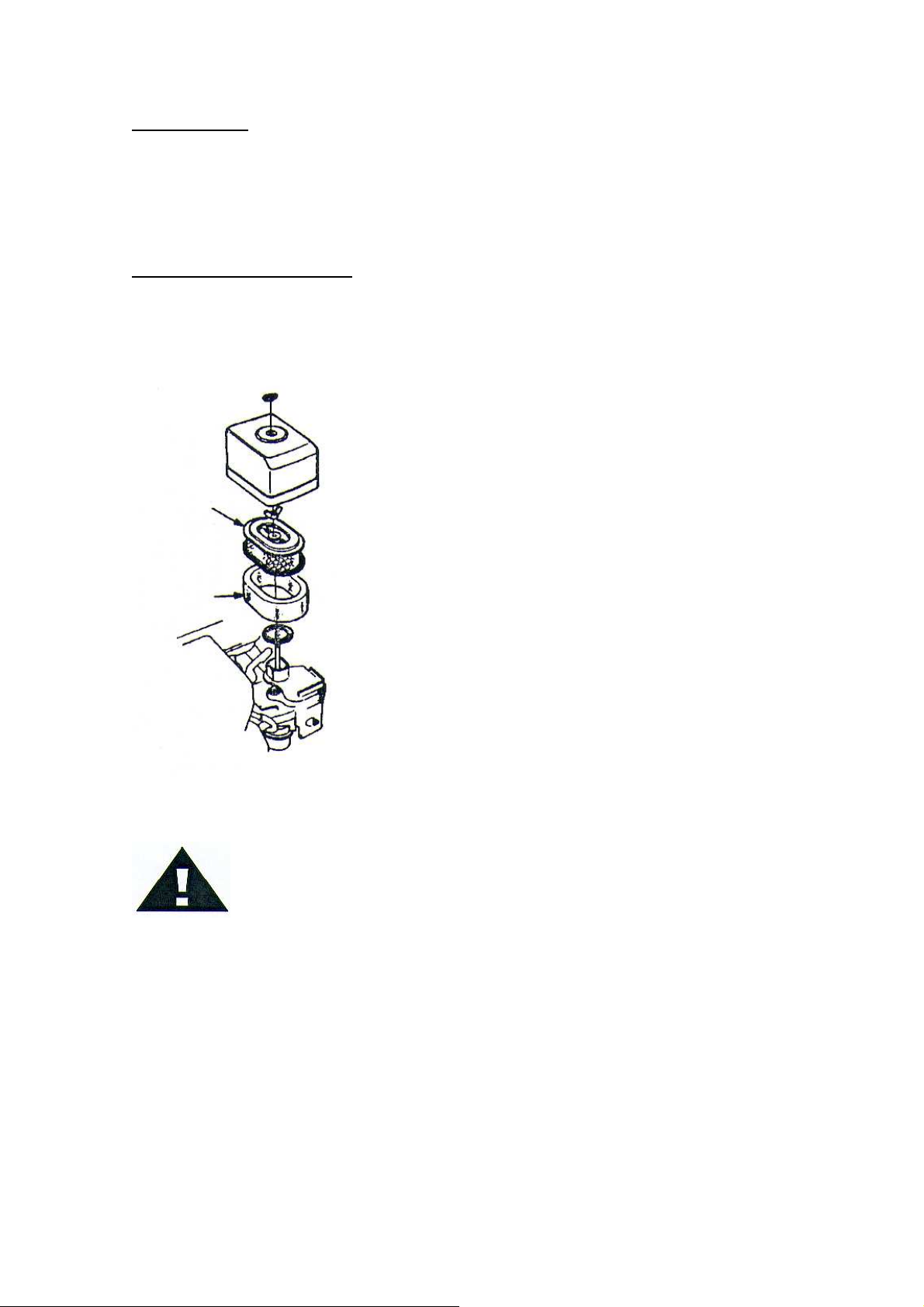
FI TRO DE AIRE
1.- El filtro de aire debe limpiarse
porque puede provocar fallos de
arranque del motor, y reducir la vida
del motor sustancialmente.
Elemento
filtrante
Espuma
filtrante
2- Para limpiar o reemplazar el filtro
de aire, aflojar la tuerca lateral de la
carcasa del filtro de aire (Figura 1),
quite la tapa y saque el filtro de aire.
Limpiar el filtro de aire mediante un
compresor y con la pistola soplar de
arriba abajo.
Figura 1: Filtro de aire
ATENCIÓN :
Nunca comprobar la correa con el motor en marcha. Puede producirse
una lesión seria, si se engancha la mano con la correa y el embrague.
Usar siempre los guantes de seguridad.
7
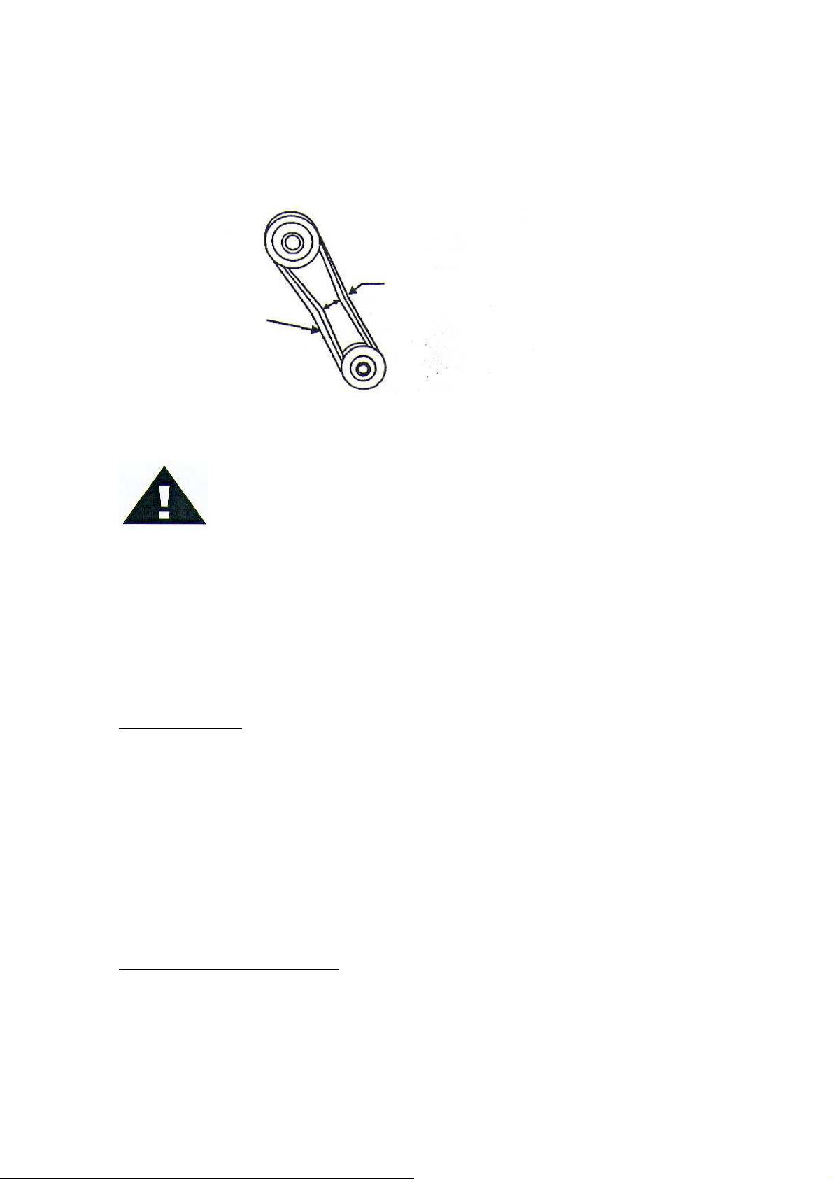
COMPROBAR Y REEMP AZAR A CORREA Y E EMBRAGUE.
Tras 200 horas , quitar la tapa y comprobar la tensión de la correa. (Figura 2). La tensión es
correcta si la correa flexa unos 10mm. Una tensión baja de la correa, provoca una perdida de
potencia del motor y reduce la vida de éste considerablemente.
Tensión correcta de 10 mm. cuando se
presiona la correa hacia el interior.
Correa trapezoidal
Figura 2. Tensión de la correa
ATENCIÓN :
Cuando la plancha compactadota pierda potencia o no vibra lo
suficiente, compruebe siempre la correa del embrague.
•Chequeo del embrague.
Comprobar simultáneamente la correa con el embrague. Una ve quitada
la correa, asegurarse que la forma de “V” de la polea no está dañada. Limpiar lo
necesario la canal en forma de “V” .Comprobar que la forma de la correa es la
adecuada, ya que su desgaste o daño, puede provocar una perdida de potencia y que la
correa patine sobre la polea.
7.- SERVICIO
Cambiar el aceite del motor cada 100 horas de funcionamiento para minimizar desgaste.
Cuando se realice el cambio de aceite, reponer con 350Ml de tipo 10W-30 motor oil.
Inspeccionar, limpiar y/o reemplazar el filtro de aire del motor regularmente, especialmente
cuando se trabaje en un ambiente polvoriento.
Inspeccionar, limpiar y/o reemplazar la buj a regularmente.
Verifique todos los elementos de anclaje, ya que la máquina está sujeta a vibraciones.
Verifique la correa de tensión, su uso y cuando no funcione correctamente, ajustar o reemplazar.
8.- ESPECIFICACIONES
MOTOR
MAMUT-10 Gasolina, 168-1 4.0 Kw
Velocidad - 3500 r.p.m.
8
PESO
MAMUT-10
64 Kg
CORREA DE ACCIONAMIENTO
1 x “A” correa trapezoidal
VIBRADOR
Frecuencia 5600 vibraciones/min
Fuerza centr fuga 10,5 KN
RODAMIENTOS
Los siguientes rodamientos están sellados:
Embrague centr fugo- lubricado por grasa
Vibrador – lubricado por baño de aceite
EMISIONES SONORAS ( de acuerdo con la normativa 2000/14/EC)
Medición de potencia de sonido: 101.5dB
Potencia de sonido máxima admisible: 104.5dB
Diferencia : 3dB
VIBRACIONES DE EMPUÑADURA ( de acuerd a la n rma ISO8662, Parte 1 , m/s2): 4-9
9.- GARANTÍA
Estos productos están cubiertos por la garant a por un per odo de 6 meses desde la fecha de
compra, contra defectos del material y el operario cumpla que:
•El producto haya llevado un mantenimiento y trabajado según el manual de
instrucciones.
•No haya sido causa de accidente, abuso o destrozo por parte del comprador.
•No haya sido reparado por personas no autorizadas.
El comprador se hace cargo del coste del transporte del equipo hasta el reparador autorizado y
se hace responsable de los riesgos del transporte, en caso de reparación del material.
10.- POSIB ES FA OS
SINTOMAS
CAUSAS POSIB ES SO UCIONES
Velocidad de motor lenta Seleccione las r.p.m. correctas
Patina embrague Verifique o reemplace el embrague
Patina correa Ajuste o reemplace la correa
Excesivo aceite Excesiva lubricación, ajuste el nivel
Malfuncionamiento de la caja vibrante Verifique la excéntrica, engranajes
Fallo de Rodamientos Reemplace los rodamientos
Velocidad de
avance lento, y
vibración débil
Insuficiente potencia del motor Verifique el motor, compresión, etc.

9
11.- POSIB ES FA OS DE MOTOR
SINTOMAS CAUSAS POSIB ES SO UCIONES
Puente en la buj a Verifique o cambie la buj a
Carbón depositado en la buj a Limpie o cambie la buj a
Cortocircuito provocado por un
mal aislamiento
Verifique el aislamiento de la buj a o
cámbiela
Dificultad al arrancar,
combustible disponible
pero no hace chispa la buj a
Buj a mal colocada Colóquela en el hueco adecuado
Interruptor ON/OFF en mal
estado, produce cortocircuito Colóquelo y reemplácelo
Ignición defectiva Reemplace el tirador
Hueco de la buj a, sucio o en mal
estado.
Colóquelo en el sitio adecuado, o
limpie el hueco
Dificultad al arrancar,
combustible disponible, y
chispa presente en la buj a. El mal aislamiento del
condensador , produce
cortocircuito
Reemplace el condensador
Tipo de gasolina incorrecto Use el adecuado Dificultad al arrancar,
combustible disponible,
chispa presente y
compresión normal
Filtro de aire sucio L mpielo o reemplácelo
Válvula de succión en mal estado Reemplácela
Anillo del pistón o cilindro roto Reemplace anillos o pistón
Dificultad al arrancar,
combustible disponible,
chispa presente y
compresión baja. Buj a y cilindro mal apretados Rosque hasta presión adecuada
Insuficiente combustible Llene lo necesario
Filtro de gasolina en mal estado Limpie o reemplace el filtro
No hay combustible en el
carburador Aire en conducto de gasolina Sangrar
Filtro de aire sucio Limpie o reemplace
Nivel inadecuado del carburador Ajústelo
Buj a defectiva Limpie o cámbiela
Agua en el conducto de
combustible
Vac elo y coloque el tipo de gasolina
adecuado
“Pérdida de potencia”
Buj a sucia Limpie o cámbiela
Calentamiento impropio de buj a Reemplace por el tipo correcto
Tipo de combustible incorrecto Reemplace a tipo de gasolina
Sobrecalentamiento del
motor Conducto de gasolina sucio Limpie los conductos refrigerantes
Ajuste del regulador incorrecto Ajuste el regulador
Régimen de giro inestable Regulador mal ajustado Remplace la arandela de regulador
Tirador sucio o en mal estado Limpie el tirador del Starter.
Tirador de starter dañado Pérdida del muelle Reemplace el muelle espiral

10
DESPIECE GENERA

11
DESPIECE GENERA
(MAMUT-10)
POSICIÓN Nº Nº REFERENCIA DESCRIPCIÓN CANTIDAD
1 100001 MOTOR HONDA GX160 1
2 100002 ASA 1
3 100003 TUERCA M10 2
4 100004 ARANDELA PLANA M10 2
5 100005 ARANDELA BLOCANTE M10 2
6 100006 TORNILLO HEXAGONAL M10x30 2
7 100007 POMO M10x25 2
8 100008 SOPORTE ASA 1
9 100009 CASQUILLO 2
10 100010 CASQUILLO ACOPLAMIENTO 2
11 100011 ARANDELA PLANA 12,5x40x30 2
12 100012 TORNILLO HEXAGONAL M12x65 2
13 100013 EMBRAGUE 1
14 100014 ARANDELA PLANA 8,5x32x2,5 2
15 100015 ARANDELA FIJACIÓN M8 2
16 100016 TUERCA HEXAGONAL M12x65 2
17 100017 PROTECCION CORREA INTERIOR 1
18 100018 PROTECCIÓN CORREA EXTERIOR 1
19 100019 PROTECCIÓN 1
20 100020 SOPORTE RUEDA 1
21 100021 BASE 1
22 100022 CIRCLIP 14 2
23 100023 ARANDELA PLANA M12 2
24 100024 RUEDA 2
25 100025 SOPORTE RUEDAS 1
26 100026 CONJUNTO VIBRADOR 1
27 100027 BASE VIBRANTE 1
28 100028 SILEMBLOCK 4
29 100029 ARANDELA PLANA M10 4
30 100030 ARANDELA FIJACIÓN M10 4
31 100031 TUERCA M10 4
32 100032 MANDO ACCELERADOR 1
33 100033 CABLE 1
34 100034 CORREA TIPO “V” 1
35 100035 LLAVE 8x7x50 1
36 100036 ARANDELA FIJACIÓN M12 4
12
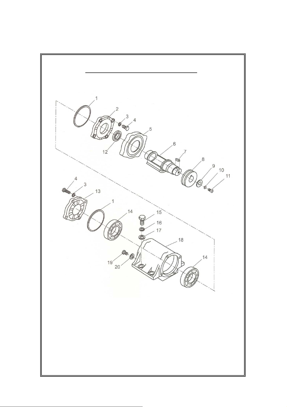
DESPIECE CONJUNTO VIBRADOR

13
DESPIECE DE CONJUNTO VIBRADOR
(MAMUT-10)
POSICIÓN Nº Nº REFERENCIA DESCRIPCIÓN CANTIDAD
1 1000501 JUNTA 2
2 1000502 TAPA TRANSMISIÓN 1
3 1000503 ARANDELA FIJACIÓN M8 8
4 1000504 TORNILLO HEXGONAL M8x25 8
5 1000505 TAPA RETEN 1
6 1000506 EXCÉNTRICA 1
7 1000507 LLAVE 8x7x18 1
8 1000508 POLEA 1
9 1000509 ARANDELA 11x40x2,5 1
10 1000510 ARANDELA FIJACIÓN M10 1
11 1000511 TORNILLO HEXAGONAL M10x40 1
12 1000512 RETEN DE ACEITE 1
13 1000513 TAPA CARCASA VIBRANTE 1
14 1000514 RODAMIENTO 6211 2
15 1000515 TORNILLO HEXAGONAL M16x40 4
16 1000516 ARANDELA FIJACIÓN M16 4
17 1000517 ARANDELA PLANA M16 4
18 1000518 CARCASA VIBRANTE 1
19 1000519 TORNILLO M12x1.25x20 1
20 1000520 ARANDELA M12 1

CONTENTS
Introduction ……………………………………………………...1
Applications ..…………………………………….……………...1
Functions and controls…………………….….………………..1
Accessories……………………………………………………...1
Hazards and risks…………………………………………….1-2
Operation ………………………………………………………..2
Care and preventive maintenance………………………… 3-4
Specification …………………………………………………….5
Transportation…………………………………………………..5
Trouble shooting………………………………….…………….6
Replacement Parts List ……………………………………7-10
INTRODUCTION
Thanks for your selection of this equipment. We have taken
care in the design, manufacture and testing of the product. It is
covered by a six month warranty. Should service or spare
parts be required, prompt and efficient service is available
from our company or our agent.
General safety instruction for the operation of power
equipment
The goal of our company is to produce power equipment that
helps the operator work safely and efficiently. The most
important safety device for this or any tool is the operator.
Care and good judgement are the best protection against
injury. All possible hazards cannot be covered here, but we
have tried to highlight some of the important items, individuals
should look for and obey caution, warning and danger signs
placed on equipment, and displayed in the workplace.
Operators should read and follow safety instruction packed
with each products.
Learn how each machines works. Even if you have previously
used similar machines, carefully check out each machine
before you use it. Get the “feel” of it and know it’s capabilities,
limitations, potential hazards, how it operates, and how it
stops.
APPLICATIONS
Trench compaction Earthworks
Road maintenance Landscaping
Brickpaving Driveway topping
FUNCTIONS AND CONTROLS
The motor is controlled by an ON/OFF switch or push button is
mounted on the motor below the fuel tank.
Tension of the drive belt is adjustable, loosen the four nuts on
the bolts which secure the motor to the base plate. Adjust the
set screws which bear against the motor crankcase to achieve
the required belt tension. Ensure that the four nuts and the set
screw locknuts are tightened after adjustment.
HAZARDS AND RISKS
NEVER allow any person to operate the machine without
adequate instruction.
ENSURE all operators read, understand and follow the
operating instructions.
SERIOUS INJURY could result from improper or careless use
of this machine.
Plates compactors are heavy units and should be positioned
by two people of appropriate strength. Using the lifting handles
provided on the machine, along with correct lifting techniques.
! MECHANICAL HAZARDS
DO NOT operate the machine unless all protective guards are
in place.
KEEP handles and feet clear of rotating and moving parts as
they will cause injury if contacted.
ENSURE that the motor operation switch is in the OFF
position and the spark plug ignition lead is disconnected
before removing the guards or making adjustments.
ENSURE both the machine and the operator are stable by
setting up on level terrain and the machine will not tip over,
slide of fall while in operation or unattended.
DO NOT leave the machine in operation while it is unattended.
ENSURE that the walls of a trench are stable and will not
collapse due to the action of the vibration, prior to
commencing compaction.
ENSURE that the area to be compacted does not contain any
“live” electrical cables, gas, water or communication services
which may be damaged by the action of vibration.
EXERCISE CARE when operating unit. Exposure to vibration
or repetitive work actions may be harmful to hands and arms.
NEVER stand on the unit while it is operating.
DO NOT increase the governed no-load motor speed above
3,500 r/min. Any increase may result in personal injury and
damage to the machine.
BE CAREFUL not to come in contact with the muffler when the
engine is hot, since it can cause severe burns.
ENSURE that the repairs to the motor and machine are
carried out by COMPETENT personnel.
! FIRE & EXPLOSION HAZARDS
PETROL is extremely flammable and explosive under certain
conditions.
2
ENSURE that the petrol is only stored in an approved storage
container.
DO NOT refuel the motor while it is in operation or hot.
DO NOT refuel the motor in the vicinity of sparks, a naked
flame or a person smoking.
DO NOT over fill the fuel tank and avoid spilling petrol when
refueling. Spilled petrol or petrol vapour may ignite. If spillage
occurs, ensure that the area is dry before starting the motor.
ENSURE that the fuel tank cap is securely fitted after
refueling.
! CHEMICAL HAZARDS
DO NOT operate or refuel a petrol or diesel motor in a
confined area without adequate ventilation.
CARBON MONOXIDE exhaust gases from internal
combustion motor driven units can cause death in confined
spaces.
! NOISE HAZARDS
EXCESSIVE NOISE can lead to temporary or permanent loss
of hearing.
WEAR an approved hearing protection device to limit noise
exposure. As required by Occupational Health and Safety
regulations.
PROTECTIVE CLOTHING
ALWAYS wear approved hearing protection when working in a
confined work space. Protective goggles and a dust mask
should be worn when working in a dusty environment.
Protective clothing and footwear may also be desirable when
working with hot mix bitumen.
! ADDITIONAL HAZARDS
Slip/Trip/Fall is a major cause of serious injury or death.
Beware of uneven or slippery work surfaces.
Exercise care when working in the vicinity of unprotected holes
or excavations.
OPERATION
Pre start-up inspection
The following Pre-start-up inspection must be performed
before the start of each work session or after every four hours
of use, whichever is first.. If any fault is discovered, the
compactor must not be used until the fault is rectified.
1.Thoroughly inspect the compactor for signs of damage.
Check components are present and secure. Pay special
attention to the belt drive safety guard fitted between the
engine and the vibrator unit.
2. Check the engine oil level and top up as necessary.
3. Check the engine fuel level and top up as necessary.
4. Check for fuel and oil leaks
Start and stop Procedure
Petrol Engine
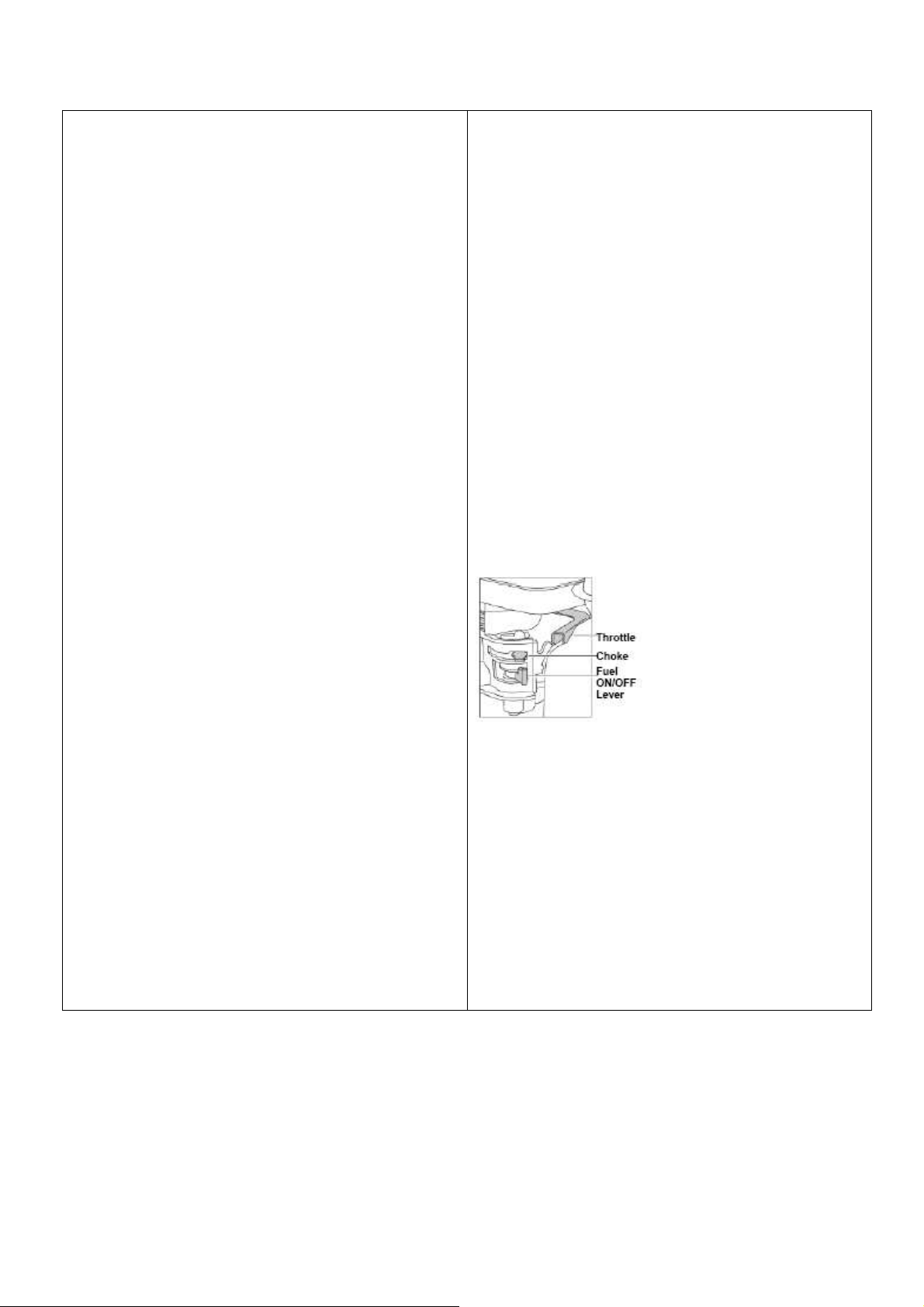
1. Open the fuel tap by moving the fuel ON / OFF lever fully to
the right.
2. If starting the engine from cold, set the choke ON by
moving the choke lever fully to the left. If restarting a warm
engine, the choke is usually not required. However, if the
engine has cooled to a degree, partial choke may be
required.
3. Turn the engine ON/OFF switch clockwise to the “1”
position.
4. Set the throttle to the idle position by moving the throttle
lever fully to the right. Do not start the engine on full throttle,
as the compactor will vibrate as soon as the engine starts.
5. Taking a firm hold of the control handle with one hand,
grasp the recoil starter handle with the other.. Pull the recoil
starter until engine resistance is felt, then let starter return.
6. Taking care not to pull the starter’s cope fully out, pull the
starter handle briskly.
7. Repeat until the engine fires.
8. Once the engine fires gradually, set the choke lever to the
OFF position by moving it to the right.
9. If the engine fails to fire after several attempts, follow the
trouble-shooting guide on page 5.
10. To stop the engine, set the throttle to idle and turn the
engine ON /OFF switch anticlockwise to the “0” position.
11. Turn the fuel off.
The machine is best suited to the compaction of bituminous
and granular materials e.g. granular soils such as silt and clay
are best compacted using the impact force produced by a
vibrating rammer.
Where possible the site should be graded and leveled before
commencing compaction.
For more information on starting and correct operating
procedures of the motor, refer to the motor operation manual
supplied with the unit.
Increase the motor speed to the maximum setting using the
hand throttle lever, before commencing compacting.
The machine should be controlled by grasping the handle with
both hands and applying restraint to control the forward
motion.
3
Steer the machine by moving the handle sideways to the right
or left.
ALWAYS maintain good footing so that you do not slip and
loose control when starting or operating the machine.
Inspect the water hose and its connections to ensure that they
do not leak.
CARE AND PREVENTIVE MAINTENANCE
Check the oil level in the motor crankcase daily.
Check the vibrator oil level weekly.
Inspect the rubber anti vibration mounts for wear or
deterioration.
Inspect the water hose and its connections to ensure that they
do not leak.
Clean the underside of the plate regularly to prevent a build up
of material.
Use unleaded grade petrol and ensure that the fuel is free
from contamination.
The vibratory motion provides a self propelling action. Position
the handle at the opposite end of the machine to the vibrator.
Start the motor using the recoil starter. (If the motor is fitted
with an on/off switch this must first be turned to ON before
starting.)Correct moisture content in soil is vital to proper
compaction. Water acts as a lubricant to help slide soil
particles together. Too little moisture means inadequate
compaction; too much moisture leaves water-filled voids that
weaken the soil’s load-bearing ability.
Compaction of dry materials will be facilitated by moistening
with a water hose fitted with a sprinkler.
Excessive watering or water content will cause the machine to
stall.
The optional water tank kit is recommended when the
machine is used on bituminous surfaces as the water film
prevents a build up of material on the underside of the plate.
CAUTION:
To make sure your plate compactor is always in good working
condition before using, carry out the maintenance inspection
in accordance with Tables 1 through 3.
TABLE 1. MACHINE INSPECTION
Item Hours of Operation
(Starting check) Every 8 hours (every day)
Loosened of lost screws Every 8 hours (every day)
Damage of any part Every 8 hours (every day)
Function of controlling
system part Every 8 hours (every day)
Vibrator oil check Every 100 hours
Vibrator oil replacement Every 200 hours
V-belt (clutch) check Every 200 hours
TABLE 2. ENGINE CHECK
(For details, see separate engine Manual)
Item Hours of Operation
Leakage of oil fuel Every 8 hours (every day)
Tightness of fastening
Threads Every 8 hours (every day)
Engine oil check and
replenishment Every 8 hours (every day)
(Replenish to specified
Max. level)
Engine oil replenishment At first 20 hours, then
every 100 hours
Air cleaner cleaning Every 50 hours
CAUTION:
CAUTION:
Inspection and other services should
always be carried out on hard and level
ground with the engine shutdown.
These inspection intervals are for operation
under normal conditions. Adjust your
inspection intervals based on the number
hours plate compactor is in use, and
particular working conditions.
Fuel piping and connections should be
replaced every 2 years.
4
Daily Service
Check for leakage of fuel or oil.
Remove soil and clean the bottom of compaction plate.
Check engine oil.
Check for loose screws including tightness. See Table 3 below
(tightening torque), for retightening.
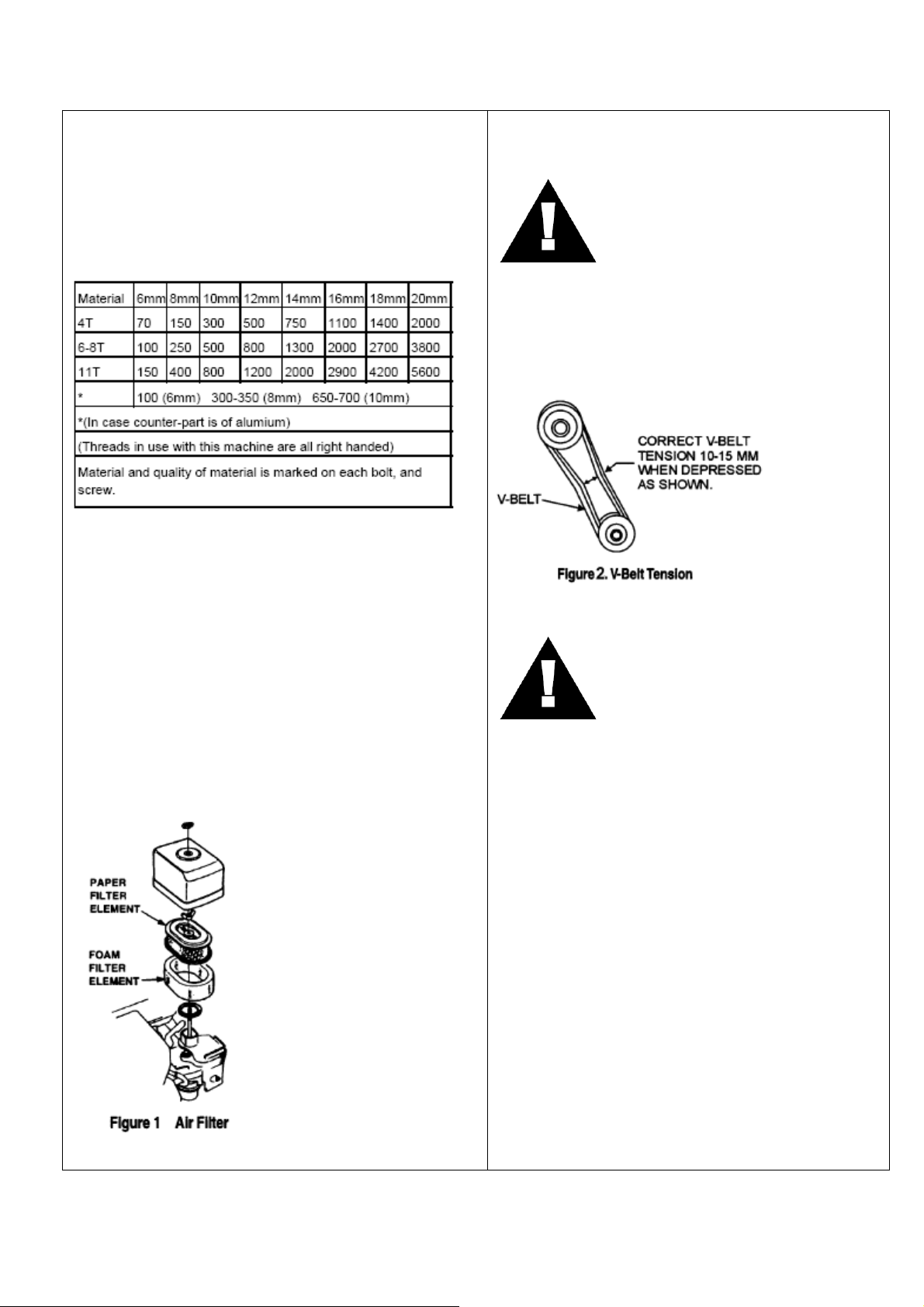
TABLE 3.
TIGHTENING TORQUE (in. kg/cm) Diameter
Changing Vibrator Oil
When changing the vibrator oil, remove the drain plug located at
the bottom-right of the vibrator, and simply tip the compactor to
drain the oil. Note that the oil will drain more easily while it is hot.
Replace the oil with 200ML of 10W-30 motor oil.
Air Filter
1. The air filter element should be cleaned because a clogged
air cleaner can cause poor engine starting, lack of power
and shorten engine life substantially.
2. To clean or replace air filter loosen the wing nut on the air
filter housing (Figure 1), remove the cover and take out air
filter cartridge. If only cleaning of the air filter is desired
blow through the air filter cartridge from the inside, moving
a jet of dry compressed air up and down until all dust is
removed.
CAUTION:
Checking and Replacing the V-belt and Clutch
After 200 hours of operation, remove the upper belt cover to
check the V-belt tension (Figure 2). Tension is proper if the
belt bends about 10mm when depressed strongly with finger
between shafts. Loose or worn V-belts reduces power
transmission efficiency, causing weak compaction and
reduces the life of the belt itself.
CAUTION:
Replacing the V-belt
Remove the upper and lower belt covers. Engage an offset
wrench (13mm) or the like to vibrator pulley (lower) fastening
bolt. Engage waste cloth or the like at midway of V-belt on the
left side and while pulling it back strongly, rotate the offset
wrench clockwise so that the V-belt will come off.
Reinstalling the V-belt
Engage V-belt to lower vibrator pulley and push the V-belt to
left side of upper clutch and, in the same manner as in
removal, rotate offset wrench clockwise so that the V-belt
goes
back on.
Checking Clutch
Check the clutch simultaneously with V-belt checking. With
belt removed, check outer drum of the clutch for seizure and
“V” groove for wear or damage with your eyes. Clean the “V”
groove as necessary. Wear of lining or shoe should be
checked with running check. If the shoe is worn, power
transmission becomes deficient and slipping will result.
NEVER
attempt to check the V-belt with the
engine running. Severe injury can occur if
your hand gets caught between the V-belt
and the clutch. Always use safety gloves.
Whenever the compactor’s vibration
becomes weak or lost during normal
operation regardless of operation hours,
check the V-belt and clutch immediately.

5
SPECIFICATIONS
Motor
MAMUT-10 Petrol, Honda GX160 4.0kW output
Governed speed - 3,500r/min
Drive Belt
1 x ‘A’ section vee belt
Vibrator
Frequency ---- 5600 vibration/min
Centrifugal force ----- 10.5 kN
Operation Mass:
MAMUT-10 64kgs
Bearings
The following bearings are sealed:
Centrifugal clutch – grease lubricated
Vibrator – oil bath lubricated
Acoustic Noise (According to 2000/14/EC)
MAMUT-10
Measured sound power level 101.5dB
Guaranteed sound power level 104.5dB
Uncertainty: 3dB
Hand-Arm-Vibration (as per ISO8662, Part 1, m/s2): 4-9
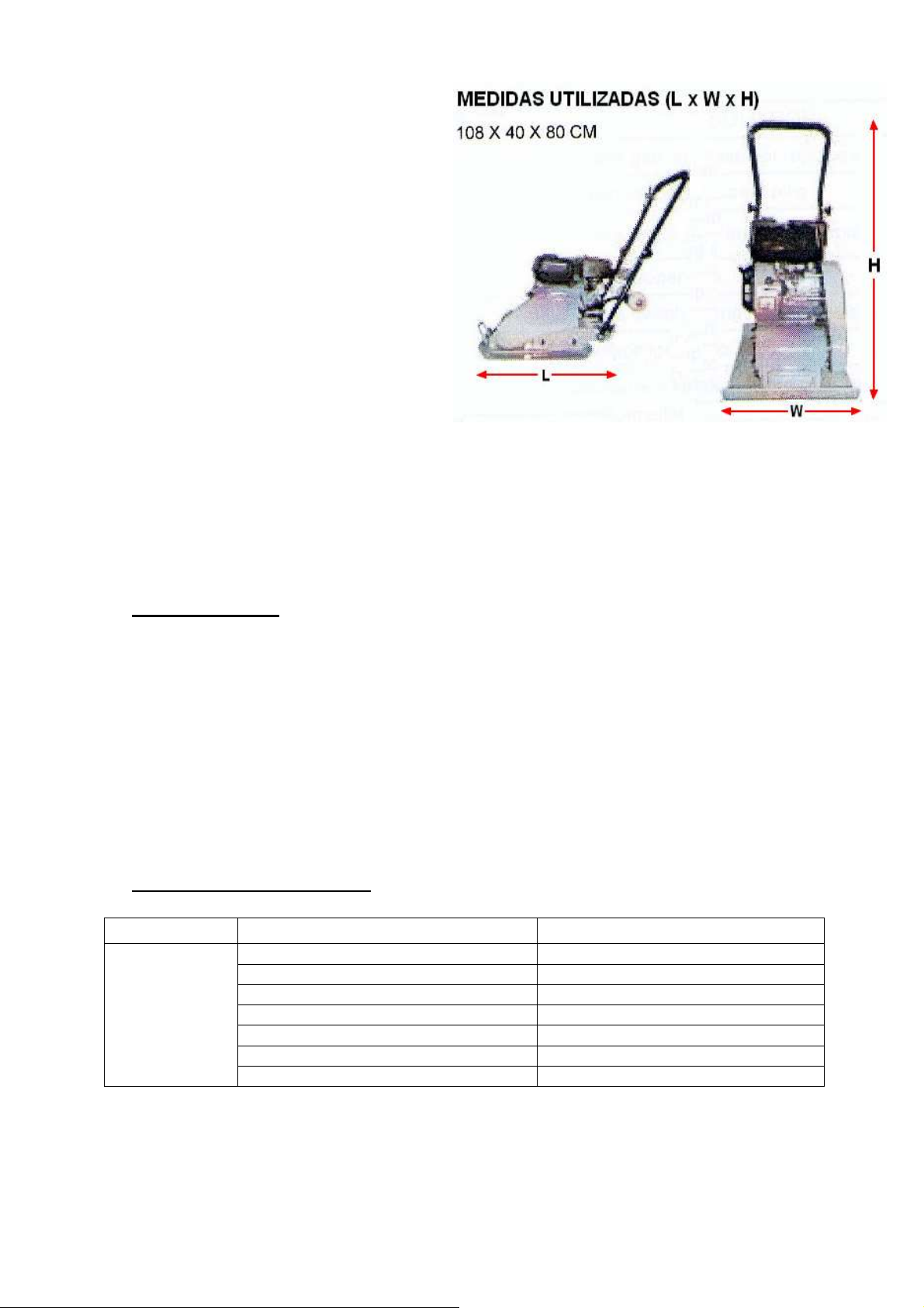
Working Size (L X W X H):
108 X 40 X 80 CM
Transportation
1. Always shut off engine when transporting machine.
2. Make sure lifting device has enough capacity to
hold machine (see identification plate on machine
for weight).
3. Use central lifting point (a) (b) and lifting hook (c)
(supplied as optional) when lifting machine.
Table of contents
Languages:
Popular Power Tools manuals by other brands

Ferm
Ferm CTM1016 Original instructions

Torq Fusion
Torq Fusion GT Series user manual

HEAVY MOTIONS
HEAVY MOTIONS HM589 Series Installation & owner's manual

OEM Products
OEM Products STORM instruction manual

Siemens
Siemens SINAMICS PERFECT HARMONY GH180 operating instructions

Craftsman
Craftsman 919.152360 owner's manual

Ferm
Ferm OTM1004 Original instructions

T-Drill
T-Drill T-60 Instruction manual and spare parts list

Go
Go Xpress 68 user manual

Hitachi
Hitachi H 90SG Handling instructions

jcb
jcb JCB-18RS Instructions & user's manual

Parkside
Parkside POF 1200 A1 Operation and safety notes translation of original operation manual


