INSTALLATION AND OPERATING INSTRUCTIONS: LKE series clamping element, electric
Zimmer GmbH ●Im Salmenkopf 5 ●77866 Rheinau, Germany ●+49 7844 9138 0 ● +49 7844 9138 80 ●www.zimmer-group.com
Installation and
operating instructions
LKE series
DDOC00215
Index e
EN/2020-07-24
Im Salmenkopf 5
D-77866 Rheinau,
Germany
+49 7844 9138 0
+49 7844 9138 80
www.zimmer-group.com
1. Supporting documents
NOTICE:
Read through the installation and operating instructions carefully before installing the product!
The installation and operating instructions contain important notices for your personal safety. They must be read and
understood by all persons who work with or handle the product during any phase of the product lifetime.
The documents listed below are available for download on our website (www.zimmer-group.com).
Only those documents currently available on the website are valid.
• Catalogs, drawings, CAD data, performance data
• Installation and operating instructions
• Technical data sheets
• General Terms and Conditions of Business with specications for the warranty entitlement
2. Safety notices
CAUTION:
Non-compliance may result in severe injuries!
Injuries or malfunctions can occur, especially with:
• Crushing during installation due to an unsecured mounting piece
ÖProtection against crushing as a result of the low stroke (max. 0.4 mm) of the element
ÖProtection by the use of bistable design engineering
• Failure to switch o the working medium during assembly or repair work on the element
• Human error
• Failure to observe the safety and warning notices during installation and commissioning
3. Proper use
NOTICE:
The element is only to be used in its original state with its original accessories, with no unauthorized changes and within the
scope of its dened parameters for use. Zimmer GmbH shall accept no liability for any damage caused by improper use.
In accordance with EN ISO 13849-1, the LKE element is a safety related component of control systems. Furthermore, we can conrm that the
product has been manufactured using the basic and proven safety principles (Appendix D.1 and D.2 of EN 13849-2) and thus dene the LKE
element as a proven component in accordance with EN 13849-1, Chap. 6.2.4, Par. b). The element can be used in control systems of Category
B or Category 1 without any further control engineering measures. A test channel must be provided for Category 2 control systems. For use in
higher control categories, the control must be multi-channel, where each channel must implement the safety function separately.
The element must not be used in any application other than those approved by the manufacturer.
Without additional protection or control engineering measures, the element must not:
• be installed in equipment used for transporting personnel (e.g. elevators)
• be used in vehicles
• be used underwater or in other liquids
• be used in a corrosive environment (e.g. in conjunction with acids)
• come in contact with abrasive media (e.g. grinding dust)
• come in direct contact with food
• be used in areas with a potentially explosive atmosphere
For questions regarding use of the LKE series element, please contact Zimmer GmbH.
4. Personnel qualications
Installation, commissioning and maintenance may only be performed by trained specialists. These personnel must have read and understood
the installation and operating instructions in full.
5. Product description
NOTICE:
The clamping process during a movement (dynamic) can lead to destruction or damage of the prole rail or the element
itself.
The element of the LKE series is a bistable element and is designed for the static clamping or securing of system components on prole rail
guides. Based on the self-locking functional principle, when the clamp is closed there is no need for any supply voltage for the actuator to
maintain the holding force. This means that in an open state, the only signal present is the DIR signal (refer to the table found under Point 6,
“Connections”).
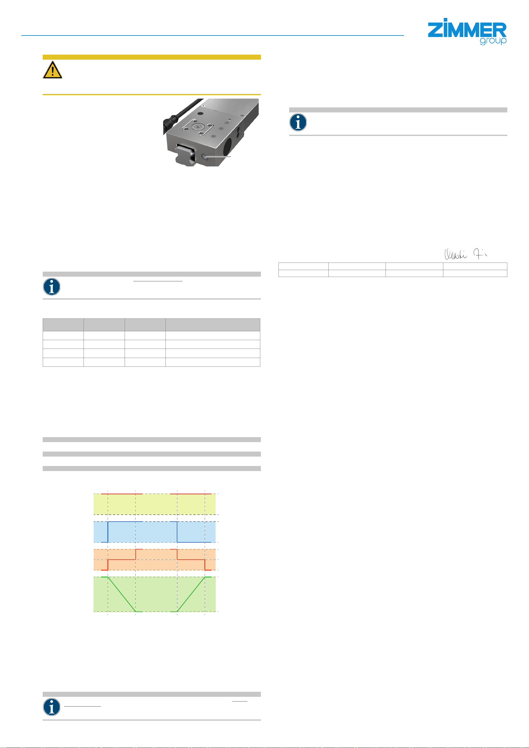
1Adjustment screw Fig. 1: LKE series element
Fig. 2: Cutaway view of the LKE series element
2Sliding block
3Housing
4Electrical connecting cable
5Prole rail guide
6Motor housing
7Electric drive
8Clamping jaws
9Eccentric gear
bl Emergency actuation
5.1 Type plate
Depending on the installation size, there is a type plate axed to the housing
of the element or the type plate information is laser-etched directly onto the
housing.
The serial number and the article number are shown on this type plate.
►The serial number should be assigned to the project.
ÖArticle number: dl
ÖSerial number: dm
XXX
XX-XXXXXX
dm
INFORMATION:
Please state the serial number in case of damage or a complaint.
This ensures an unambiguous classication in the event of an update or an overhaul.
Zimmer Customer Service is available to provide you with assistance if you have any further questions.
6. Connections
The element is connected by means of an 8-pin M12x1 plug cable.
1
2
3
4
5
6
7
8
︵ ︵ ︵ ︵ ︵ ︵ ︵ ︵
1White DIR signal, open=1 (24V)/close=0 (0V)
2Brown Output status "closed"
3Green Output status "error"
4Yellow Voltage supply 24 V / Logic
5Gray Output status "open"
6Pink Voltage supply 24 V / Motor
7Blue Not used
8Red Voltage supply 0 V / GND
7. Installation
CAUTION:
If the fastening screws are tightened when the element is not clamped, the element can shift and consequently be unable
to achieve the optimum clamping force! Furthermore, the guide rail could become damaged.
WARNING:
Risk of injury in case of unexpected movement of the machine or system into which the element is to be installed.
► Switch o the power supply to the machine before all work.
►Secure the machine against being switched on unintentionally.
►Check the machine for any residual energy.
7.1 General installation information
The element must be mounted on a suitable mounting surface in accordance with the atness specications.
• Permissible atness imperfection: 0.03
The element can be mounted on the mounting piece from above using the threads.
• Make sure the mounting piece is suciently rigid and at.
• Screw-in depth ≥0.9 x Ø
• The mounting screws are not included in the scope of delivery.
• Strength class of the mounting screws ≥8.8 (DIN EN ISO 4762)
• Observe the tightening torque of the mounting screws (www.zimmer-group.de/de/lt-td)
ÖZimmer GmbH recommends verifying the permitted load-carrying capacity of the required screw connections in accor-
dance with VDI 2230.
• The exact mounting positions can be found on the technical data sheet on our website.
7.2 Installing the element
NOTICE:
Access for emergency actuation bl and access to the element’s adjustment screw 1must be ensured.
ÖThe element does not have any guide characteristics!
INFORMATION:
The element is allowed to be closed only if the associated prole rail is between the contact surfaces!
• There must be no control voltage present when an electrical connecting cable 4is connected or disconnected!
• Avoid changing signals before the specified time (opening/closing), otherwise there may be a malfunction.
• Unauthorized opening of the housing shall void any warranty claim.
If the element is not yet connected to a power supply, the element can be opened and closed manually using the emergen-
cy actuation bl.
ÖTurning counterclockwise = close
ÖTurning clockwise = open
►Position the element on the linear guide.
ÖIf a spacer plate is used, it is inserted between the element and the
mounting piece as level compensation.
►Screw the screws into the tapped holes of the sliding block 2and
tighten them only slightly.
►The element centers itself as a result of a single cycle.
►Close the element.
► Tighten the fastening screws crosswise using the specied torque.
►Open the element.
7.3 Design of the mounting piece
NOTICE:
The user alone is responsible for ensuring that the mounting piece is suciently rigid in terms of the Machinery Directive
2006/42/EC.
Zimmer GmbH accepts no liability for consequential damages to the element, injury to personnel or damage to the system
in which the element is installed.
INFORMATION:
The holding force is the maximum force that can be generated in the axial direction. The specied holding forces are tested
on every clamping and braking element before delivery using a lightly lubricated rail (ISO VG 68).
Using other oil or lubricating substances can inuence the coecient of friction, which can cause a loss of holding force in
individual cases.
We reserve the right to make additional changes in the course of further development.
►Make sure that the mounting faces (sliding block 2) are at (0.03 mm).
►The extension cord, which lengthens the power cable 4, must not
exceed a length of 10 m.
►The electric connecting cable 4must be relieved of strain at the mount-
ing piece. The cable must be installed in such a way that the cable cannot
rub against the rail or get pinched.
► The 3D data for the prole rails is not necessarily true to detail in the area
of the rail groove. Refer to the catalog or product selection on our website
to see whether an element ts on the selected rail.
0,03
7.4 Tolerance compensation
CAUTION:
The adjustment screw must not be turned using force above the specied tolerances of ±0.05 mm!
The prole rails have a conventional tolerance of ± 0.05 mm. The adjustment
screw 1 for the passive contact prole can be used to compensate this
tolerance and achieve a centered positioning for the element.
►You can use an Allen key to turn the adjustment screw 1and adjust the
element to the measured dimension of the rail.
► This adjustment is to be set and checked before nal assembly of the
element.
The centered setting of the element for the prole rail has a critical inuence
on achieving the maximum possible holding force.
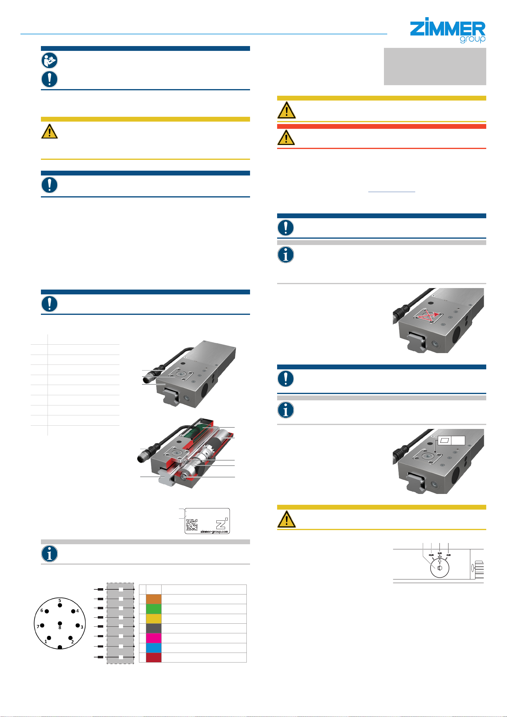
Three markings are engraved on the housing of the element.
Marking fm:Nominal dimension of the rail (xx,xx)
Marking fn:Nominal dimension of + 0.05 mm
Marking fo:Nominal dimension of - 0.05 mm
fm
1 fn fo