AEC ILLUMINAZIONE LOGIKA 2 Manual

MOUNTING AND MAINTENANCE
INSTRUCTION
LOGIKA 2 AS-OC-OP_IM_ENG - Rev.09 of 16/09/16 Pag. 1 of 3
AS - OC - OP
Made in Italy
Pic. 1
Pic. 2
Pic. 3
Pic. 4
MOUNTING AND MAINTENANCE
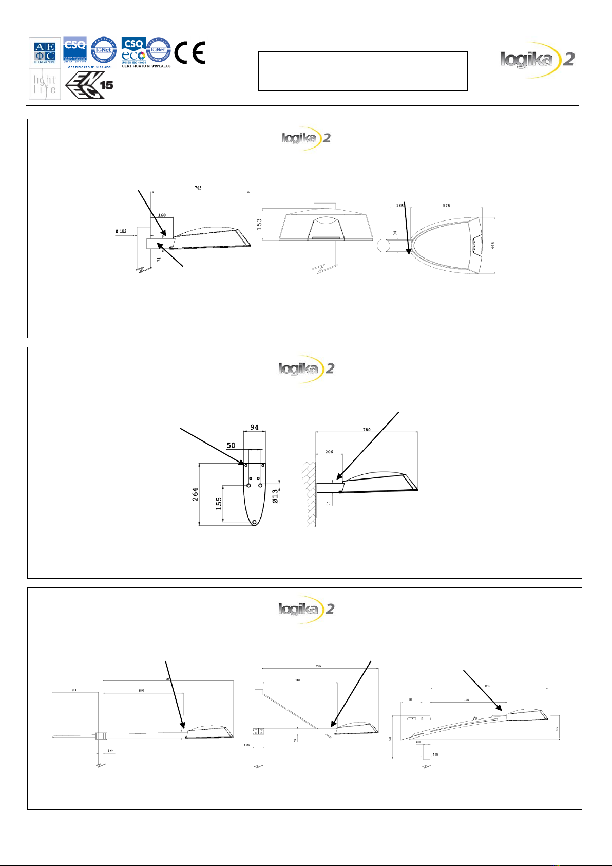
The connection system, on pole/bracket or wall
mounting, allows to install the luminaire parallel to
the street.
See related section for particular fixing on pole,
bracket or wall mounting.
To gain access to the electrical parts, unlock and
open the frame [Pic. 1].
The lower frame will open, stopping in vertical
position [Pic. 2].
To connect the luminaire to the electrical line,
insert the cable into the cable clamp and then
connect it to the on-load switch. Tighten the cable
clamp with an adjustable wrench of 25mm applying
a twisting moment of 5Nm.
The feeding of the fitting must be done with a
bipolar cable with nominal diameter between 7 and
13 mm.
When it is necessary, you can take away the gear
tray, loosen the two screws (A-B) and disconnect
the main and lamp connectors (C) [see Pic. 3-4].
To reinsert the gear tray, put it right position and
then tighten the screws and reinsert the connector.
ATTENTION, high voltage danger with RX7
and FC2 lamp holder.
B
C
A
H
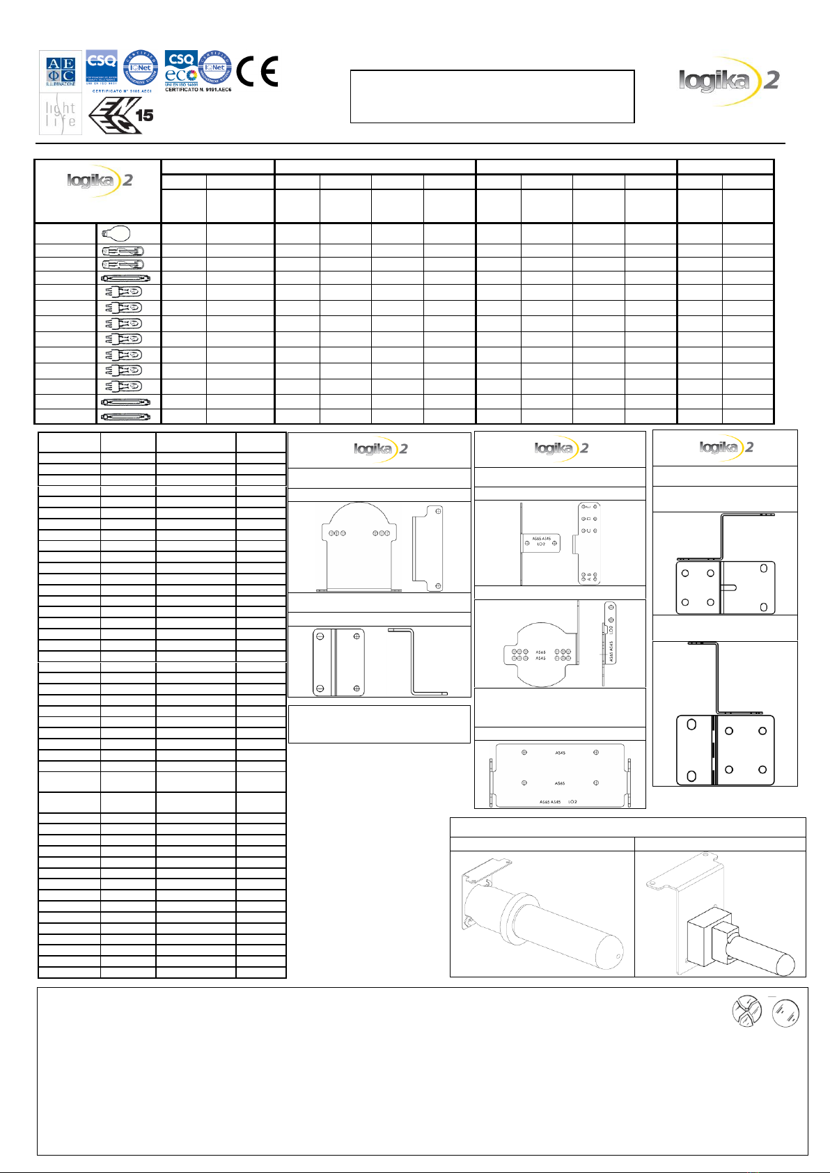
Model
Power
Weight [gr]
Empty
With control
gear
70 W
7000
10400
100 W
10500
150 W
11500
250 W
12000
Suggested height of installation
Model
Power [W]
H min [m]
H max [m]
70W
5
10
100W
7
12
150W
7
13
250W
7
14
A- Ballast
L- Lamp
f–Fuse
(500V)
C- Capacitor
Z- Ignitor
WIRING SCHEME
SHP - White Son
MHL
WIRING SCHEME
Cosmopolis
Fluorescenti Compatte
L
N
L
Out
A
In
Form factor: 1,2
0.08 m2
Area exposed to wind
0.21 m2
ELECTRICAL LINE CONNECTION
< 25mm
67mm
In order to insure double insulation
characteristic of the feeder cable, we
would advise that you first secure the
feeder cable to the internal cable
clamp, remove approximately 25mm of
external sheathing, and 6mm of
sheathing from the internal wires.
This product complies with EU Directive 2002/95/EC.
The crossed-out wastebasket symbol on the appliance
means that at the end of its useful lifespan, the product
must be disposed of separately from ordinary household
wastes. The user is responsible for delivering the appliance
to an appropriate collection facility at the end of its useful
lifespan. Appropriate separate collection to permit
recycling, treatment and environmentally compatible
disposal helps prevent negative impact on the environment
and human health and promotes recycling of the materials
making up the product. For more information on available
collection facilities, contact your local waste collection
service.
INFORMATION TO THE CUSTOMERS
Directive 2002/96/EC (Waste Electrical and
Electronic Equipment - WEEE): information for
users.
MOUNTING AND MAINTENANCE
INSTRUCTION
LOGIKA 2 AS-OC-OP_IM_ENG - Rev.09 of 16/09/16 Pag. 2 of 3
AS - OC - OP
Made in Italy
Post top mounting with MT bracket
Dimensions
Mounting
Mount the fixing support of LOGIKA 2 to the pole through the four 8MA x 100 (A) screws. Tighten the four screws with a set
screw wrench of 6mm applying a twisting moment of 10Nm. Tighten the two screws 8MA x 14 with a set screw wrench of 5mm
applying a twisting moment of 10Nm to fix the fitting in horizontal position (B). See the MT mounting instruction for others
details.
B
A
B
Wall mounting
Dimensions
Mounting
Fix the LOGIKA 2 support to the plate trough the four 8MA x 100 screws (A). Tighten the four screws with a set screw wrench of
6mm applying a twisting moment of 10Nm. Tighten the two 8MA x 14 screws with a set screw wrench of 5mm applying a
twisting moment of 10Nm to fix the fitting in horizontal position (B). See the plate mounting instruction for others details.
A
B
Bracket mounting (MH - MI - MD)
Dimensions
Mounting
Put the LOGIKA 2 in position and fix it trough the 8MA x 14 screws (A). Tighten the screws with a set screw wrench of 5mm
applying a twisting moment of 10Nm (A). See the brackets mounting instruction for others details.
A
A
A
MOUNTING AND MAINTENANCE
INSTRUCTION
LOGIKA 2 AS-OC-OP_IM_ENG - Rev.09 of 16/09/16 Pag. 3 of 3
AS - OC - OP
Made in Italy
Ta = 30°C
Cosmopolis White
MHL
SHP
White Son
60W
140W
70W
100W
150W
250W
70W
100W
150W
250W
50W
100W
Optic
Optic
Optic
Optic
Optic
Optic
Optic
Optic
Optic
Optic
Optic
Optic
E27
OC
NO OP
NO OP
E27
OC
OC
E40
NO OP
NO OP
AS
NO OP
NO OP
AS
FC2
NO OC
NO OC
G12
OC
NO OP
AS
G22
AS
GX12
OC
PG12-1
OC
NO OP
PG12-2
OC
PGX12-2
NO OP
PGZ12
OC
NO OP
RX7S
OC
OC
RX7S-24
OPTIC
LAMP
HOLDER
LAMP
POS
AS45 / AS65
E27
100W MHL-E
B
AS45 / AS65
E27
150W MHL-E
B
AS45 / AS65
E40
100W MHL-T
C
AS45 / AS65
E40
150W MHL-T
C
AS45 / AS65
E40
250W MHL-T
E*
AS45 / AS65
E40
250W MHL-T
D**
AS45 / AS65
E40
100W SHP-T
C
AS45 / AS65
E40
150W SHP-T
C
AS45 / AS65
E40
250W SHP-T
E
AS45 / AS65
FC2
250W MHL
2A
AS45 / AS65
FC2
250W SHP
2B
AS45 / AS65
G12
150W MHL
B+spacer
AS45 / AS65
G12
250W MHL
B+spacer
AS45 / AS65
G22
250W MHL
B
AS45 / AS65
PG12-1
100W SHP-White
A
AS45 / AS65
PGX12-2
150W MHL
A
AS45 / AS65
RX7S
150W MHL
1A
AS45 / AS65
RX7S-24
150W MHL
1A
AS45 / AS65
RX7S-24
150W SHP
1A
AS45 / AS65
PGZ12
140 CPO
A
OC
E27
70W MHL-T
B
OC
E27
70W MHL-E
C
OC
E27
100W MHL-E
C
OC
E27
150W MHL-E
C
OC
E27
70W SHP-T
B
OC
E40
100W MHL-T
A
OC
E40
150W MHL-T
A
OC
E40
100W SHP-T
A
OC
E40
150W SHP-T
A
OC
G12
70W MHL
B
rot+spacer
OC
G12
150W MHL
B
rot+spacer
OC
PG12-1
100W SHP-White
C
OC
PG12-2
70W MHL
C
OC
PGX12-2
150W MHL
C
OC
RX7S
70W MHL
DA Plate
OC
RX7S
150W MHL
DA Plate
OC
RX7S
70W SHP
DA Plate
OC
RX7S-24
150W MHL
DA Plate
OC
RX7S-24
150W SHP
DA Plate
OC
PGZ12
60W CPO
E
OC
PGZ12
140W CPO
D
OP
FC2
250W MHL
OP
FC2
250W SHP
OP
RX7S
150W MHL
OP
RX7S-24
150W MHL
OP
RX7S-24
150W SHP
AS45/AS65
Lamp holder support
Lamp holder plate
AS45/AS65 double
attachment
Lamp holder plate
OP
Lamp holder plate
150W
Lamp holder plate
250W
ATTENTION
a) The luminaire can be installed close to flammable surfaces.
b) High voltage danger with RX7 and FC2 lamp holder
c) Class II luminaires must be installed in such a way that it is impossible for any exposed metal part to come in contact with electrical components.
d) Luminaires for Metal Halide lamps must be always complete with its protective screen.
e) For luminaires with Metal Halide lamps, damaged protective shields can only be replaced with original AEC Illuminazione’s replacement shields.
f) On luminaires for Metal Halide lamps use only UV Stop protected lamps.
g) This luminaire has been designed and manufactured following all relevant standards. The installation must be done by experienced personnel and
following the instructions.
The present instruction paper has to be kept for any future maintenance operation on the luminaire.
Non compliance with the above will automatically release AEC Illuminazione Srl from any responsibility.
*: lamp with ceramic burner
**: lamp with quartzitic burner
OC Optic
NORMAL position
ROTATED position
OC
Lamp holder plate
OC double attachment
Lamp holder plate D.A.
Other AEC ILLUMINAZIONE Lantern manuals

Popular Lantern manuals by other brands

HEPER
HEPER GOLEDO-T 128 LED Installation & maintenance instructions

BEGA
BEGA 50 337.1 Instructions for use

Maxim Lighting
Maxim Lighting Balboa VX quick start guide

FLOS
FLOS TAB T LED Instruction for correct Installation and Use

Visa Lighting
Visa Lighting ASTA Series installation instructions

MOOD
MOOD SOL-CIL895A instruction manual

Martin
Martin Architectural Rail Light Installation guide and user's manual

Leviton
Leviton MSU-DFX Series Installation instruction

Lighting Technologies
Lighting Technologies HB LED LOGISTIC Series manual

WE-EF
WE-EF CFS500 Series Installation and maintenance instructions

Velleman
Velleman EFCL01 quick guide

Portfolio
Portfolio DHO005-R1-BB-A1 manual


