AEC ILLUMINAZIONE ITALO 3 Manual

ITALO 3_IM_ENG - Rev.04 of 27/10/14 Page 1 of 4
MOUNTING AND MAINTENANCE
INSTRUCTION
0°
10°
ATTACHMENT
Pic. 2
M12 screws + split washer and plain washer
Set screw wrench: 10mm
Twisting moment: 15Nm
20°
5°
15°
M10 (3/8") Set screws
Set screw wrench: 5mm
Twisting moment: 15Nm
--------------------------------
M10 nuts
Adjustable wrench: 17mm
Twisting moment: 15Nm
Pic. 4
Pic. 5A – Post-top mounting
Fig. 5B – Bracket mounting
Pic. 3A – Post-top mounting Pic. 3B – Bracket mounting
Sign reference
0°
-10°
-20°
-5°
Sign reference
-15°
Pic. 1
MOUNTING AND MAINTENANCE INSTRUCTION
Post-top or bracket mounting
ITALO 3 is equipped with an universal attachment (post-top or bracket mounting).
- Attachment Ø60-76mm / Ø2-3/8" - 3"
Place correctly the attachment as indicated in Pic. 5A (Post-top) or in Pic. 5B
(Bracket).
Fix the attachment to the luminaire with the two M12 screws as indicated in Pic. 2.
Possible to tilt:
- Post-top mounting: 0°, +5°, +10°, +15°, +20°
- Bracket mounting: 0°, -5°, -10°, -15°, -20°
Use the proper sign as indicated in Pic. 3A and 3B.
The regulation of the luminaire can to be done loosing the two screws (Pic. 2).
Fix the attachment to the post-top or to the bracket as indicated in Pic. 4.
To avoid any possible unscrewing of set screws, four M10 (3/8") nuts have
to be tightened on the set screws as indicate in Pic. 4.
ITALO 3_IM_ENG - Rev.04 of 27/10/14 Page 2 of 4
MOUNTING AND MAINTENANCE
INSTRUCTION
Pic. 6
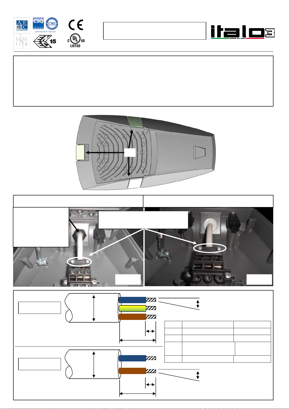
Electrical line connection
To gain access to the electrical line, unlock the 3 closing hooks (A – Pic. 6) and lift the upper frame up to the action of the two
hinges.
- Luminaire with cable gland: follow the directions in Pic. 8. You must secure the external cable by tightening
plastic holder on the "on-load switch".
Luminaire with membrane:follow the directions in Pic. 9. You must secure the external cable by tightening
plastic holder on the "on-load switch".
In case the luminaire is equipped with PLM device, before closing the luminaire, annotate the serial number of the device.
Pic. 8 Pic. 9
Tighten the screws to the complete
closure of the cable holder
M20 plastic cable gland
Adjustable wrench: 24mm
Twisting moment: 3.5Nm
--------------------------------
M25 plastic cable gland
Adjustable wrench: 30mm
Twisting moment: 5Nm
CABLE GLAND MEMBRANE
A
Cable gland Membrane
A 6 ÷7 mm / 1/4" 6 ÷7 mm / 1/4"
B < 25m / 1" < 25mm / 1"
C M20: 8 ÷12mm / .31"÷.47"
M25: 10 ÷ 17mm / .39"÷.67"
8 ÷ 12mm / .31"÷.47"
D ≤2.5mmq / 12AWG ≤2.5mmq / 12AWG
CLASS I
CLASS II C
A
B
A
B
C D
D
ITALO 3_IM_ENG - Rev.04 of 27/10/14 Page 3 of 4
MOUNTING AND MAINTENANCE
INSTRUCTION
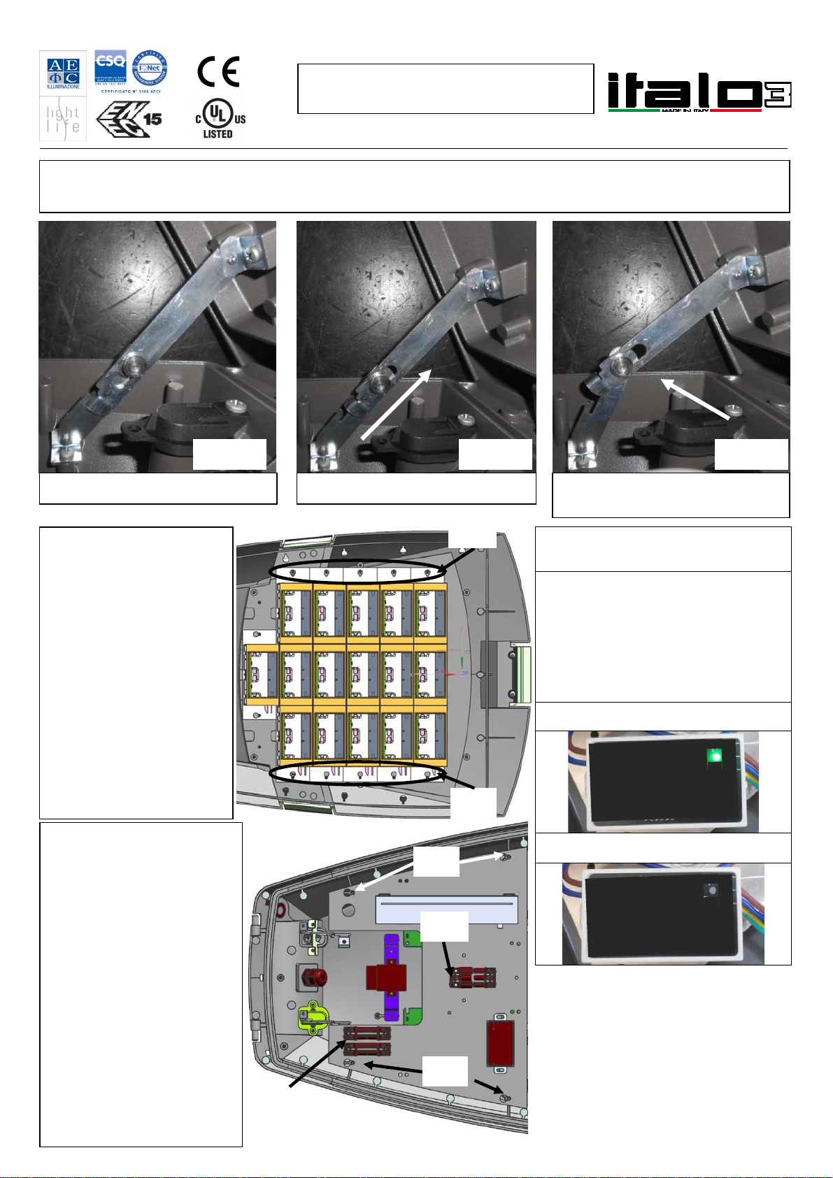
Luminaire closure
To close the luminiare, follow the directive from Pic. 10 to Pic. 12.
Pic. 10 Pic. 11 Pic. 12
Lift the upper frame Unlock the two hinges and move down the
upper frame
Initial position
LED modules extraction
1) Disconnect the LED
connectors (C);
2) Loosen the screws (E)
3) Extract the LED
modules.
LED module repositioning
1) Replace in the original
position the LED
modules;
2) Tighten the screws (E);
3) Connect the LED
connectors (C).
Gear tray extraction
1) Disconnect the mains
connector (B)
2) Disconnect the LED
connectors (C);
3) Loosen the 4 screws (D)
4) Extract the gear tray.
Gear tray repositioning
1) Replace in the original
position the gear tray;
2) Tighten the 4 screws (D);
3) Connect the LED
connectors (C);
4) Connect the main
power cable to
connector (B). Pic. 14
Pic. 13
C
E
E
B
D
D
SPD MAINTENANCE
The protection device is equipped with
system that excludes power supply at the
end of life of the luminaire.
If the luminaires switches-off when the
system is still fed, the activity of the
protection device should be checked
looking at signaling LED.
To check this, use the appropriate tool
asked the manufacturer for instructions.
LED ON _ Right functioning of the SPD
LED OFF _ End of life SPD, replace the
SPD
ITALO 3_IM_ENG - Rev.04 of 27/10/14 Page 4 of 4
MOUNTING AND MAINTENANCE
INSTRUCTION
NOTE
a) The luminaire can be installed close to flammable surfaces.
b) Class II luminaires must be installed in such a way that it is impossible for any exposed metal part to come in contact with electrical
components.
c) The device has been designed in compliance with the current standards; it is necessary that the installation is done properly, according with the
instructions supplied.
d) The present instruction paper has to be kept for any future maintenance operation on the luminaire. Non compliance with the above will
automatically release AEC Illumination from any responsibility.
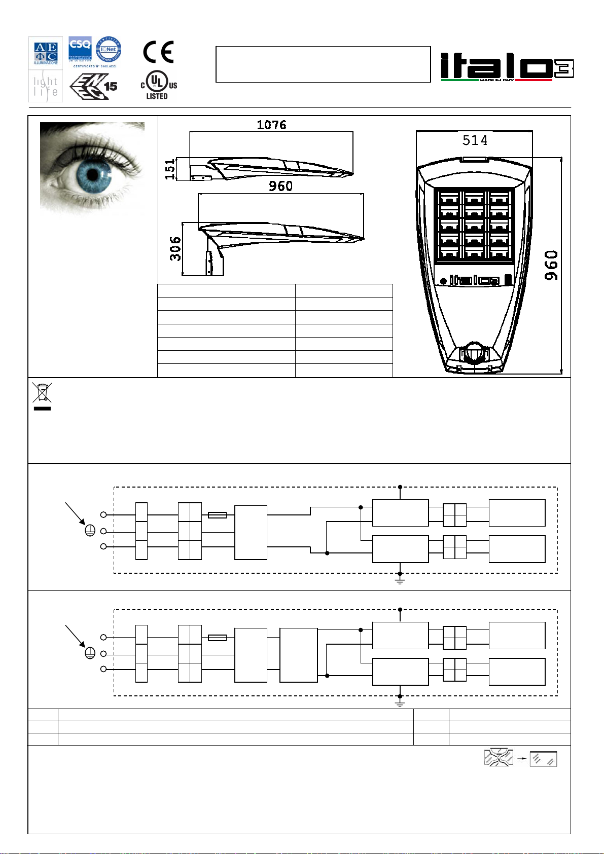
Protection ground
(only in class I)
L
N
PSU2
WIRING SCHEME
S1 F1
(
o
p
tion
)
F Fuse 110Vac 10A (provide the fuse externally if not supplied with the luminaire) PD Protection device
CN Connector CD Control device
S On-load switch PSU Power Supply
CN1
The crossed-out wastebasket symbol on the appliance means that at the end of its useful lifespan, the product must be disposed of separately
from ordinary household wastes. The user is responsible for delivering the appliance to an appropriate collection facility at the end of its useful
lifespan. Appropriate separate collection to permit recycling, treatment and environmentally compatible disposal helps prevent negative impact
on the environment and human health and promotes recycling of the materials making up the product. For more information on available
collection facilities, contact your local waste collection service.
Side area: 1.07 Sq.f / 0.10m2
Base area: 4.3 Sq.f / 0.40m2
Form factor: 1.2
Max height of installation: 15m / 50'F
Ta 35°C / 95F
Use Indoor / Outdoor
Max weight 19kg / 42 Lbs
ITALO 3 luminaire
is classified under
“EXEMPT GROUP”
according to
photobiologycal
safety standard
IEC/EN 62471.
NO RISK
for the operators
and end users.
PSU1 LED
modules
LED
modules
PD
CN2
CN3
Protection ground
(only in class I)
L
N
PSU2
WIRING SCHEME WITH PLM
S1 F1
(
o
p
tion
)
CN1
PSU1 LED
modules
LED
modules
CN2
CN3
PD CD
Other AEC ILLUMINAZIONE Lantern manuals


