Leviton MSU-DFX Series User manual

Page 1
MSU-DFX SERIES
Installation Instruction
ERP: IIS00344
03/11/2022 Rev1.0
IMPORTANT SAFEGUARDS
When using electrical equipment, basic safety precautions should always be followed including the following:
READ AND FOLLOW ALL SAFETY INSTRUCTIONS
a) This equipment is designed for use with germicidal UV radiation sources and must be installed in compliance
with competent technical directions to prevent risk of personal injury from UV radiation.
b) UV radiation can pose a risk of personal injury. Overexposure can result in damage to eyes and bare skin. To
reduce the risk of overexposure this equipment must be installed in accordance with the manufacturer’s site plan-
ning recommendations. This may include instructions on the relative location of each germicidal system compo-
nent, the minimum distances between UV-generating devices and other objects or surfaces, and protection from
line-of-sight exposure to UV radiation in occupied spaces located above the equipment mounting area (e. g. upper
floor balconies, open staircases, etc.)
c) UV and optical radiation can be reflected by surrounding surfaces such as ceilings and walls. Since the reflec-
tive properties of surfaces can vary widely, it should be considered as part of site planning. Follow the manufactur-
er’s recommendations for selecting appropriate ceiling and wall finishes.
d) IT IS THE RESPONSIBILITY OF THE INSTALLER TO ENSURE THAT PERSONS WILL
NOT BE EXPOSED TO EXCESSIVE UV OR OPTICAL RADIATION DURING EQUIPMENT
OPERATION. THIS WILL REQUIRE THE INSTALLER TO CONDUCT AN ASSESSMENT OF
IRRANDIANCE OR ILLUMINANCE LEVELS IN THE SURROUNDING OCCUPIED SPACES
PRIOR TO OCCUPANCY.
e) Equipment should be mounted in locations and at heights where it will not readily be subjected to tampering by
unauthorized personnel.
f) Maintenance and servicing of this UV generating equipment shall be performed by authorized personnel. Ser-
vice personnel must wear appropriate Personal Protective Equipment (PPE) if the equipment will be in operation
during the maintenance or servicing work. Contact the equipment manufacturer for PPE recommendations and
guidance.
g) The use of accessory equipment not recommended by the manufacturer may cause an unsafe condition.
h) Do not use this equipment for other than intended use.
i) This fixture is not suitable for residential use.
SAVE THESE INSTRUCTIONS

Page 2
MSU-DFX SERIES
Installation Instruction
ERP: IIS00344
03/11/2022 Rev1.0
Manufacturer is not responsible for any injuries due to the improper installation or handling of its products.
Hard Ceiling Flange
NOTES
Installation should be completed by an individual familiar with the construction and operation of the luminaire.
Installation of luminaire must be in accordance with nation and local building and electrical codes.
Carefully read and follow all warnings and instructions before installing or servicing the luminaire.
Instructions do not cover all details and all possible product configurations
Do not restrict luminaire ventilation.
Ensure LED luminaire is not covered with material that will prevent convection or conduction cooling.
Do not exceed luminaire’s maximum ambient temperature.
Ensure LED luminaire has the correct polarity before installation.
Based on maximum voltage restrictions for class 2 circuits in Canadian Electrical Code, the output cannot be accessible. This product has accessible
output terminals. This product complies with this requirement since the installation instruction requires installation in Restricted Access Area.
WARNINGS
Electric shock:
Disconnect or turn off power before installing or servicing luminaire.
All electrical wiring to be completed by a qualified licensed electrician
in accordance with local and National/Canadian Electrical Code.
Ensure supply voltage corresponds with the correct ballast/driver
voltage.
Avoid exposing wiring to metal edges and sharp objects.
Ensure that the luminaire is properly grounded to prevent electric
hazards.
Fire:
Keep flammable and combustible materials away from the light source and/or
lens.
Use correctly rated supply conductors as indicated by product labeling.
Burn:
Allow luminaire to cool before handling luminaire.
Personal Injury:
Wear safety glasses and gloves when handling the luminaire to avoid physical
injury.
Avoid direct eye contact with light source.
Always support the weight of the luminaire.
Note:
The models requires an accurate cutout of the luminaire opening. It is essential that the opening room side edge be flat
to ensure the integrity of the seal.
Use 1-5/8 Unistrut (not included) or equivalent support beams on all four sides above the opening edge. The support struc-
ture should be suitably rigid and secured to support the weight of the luminaire. (Minimum thickness of ceiling and framing
is 1 1/2”, maximum is 2 3/4”).
Only qualified electricians should make the electrical connections and should ensure that all Building and Safety code re-
quirements are observed.
CRU & MD1U when supplied with white + red or white + green LEDs, are to be separately switched externally. Also they
are NOT to be operated simultaneously.
Mounting:
1. Disconnect electrical power intended to be connected to the luminaire.
2. Locate and cut the required opening in the ceiling.
3. Install and secure the required support structure.
4. Remove the lens and door assembly by removing all twelve self-sealing screws from the luminaire.
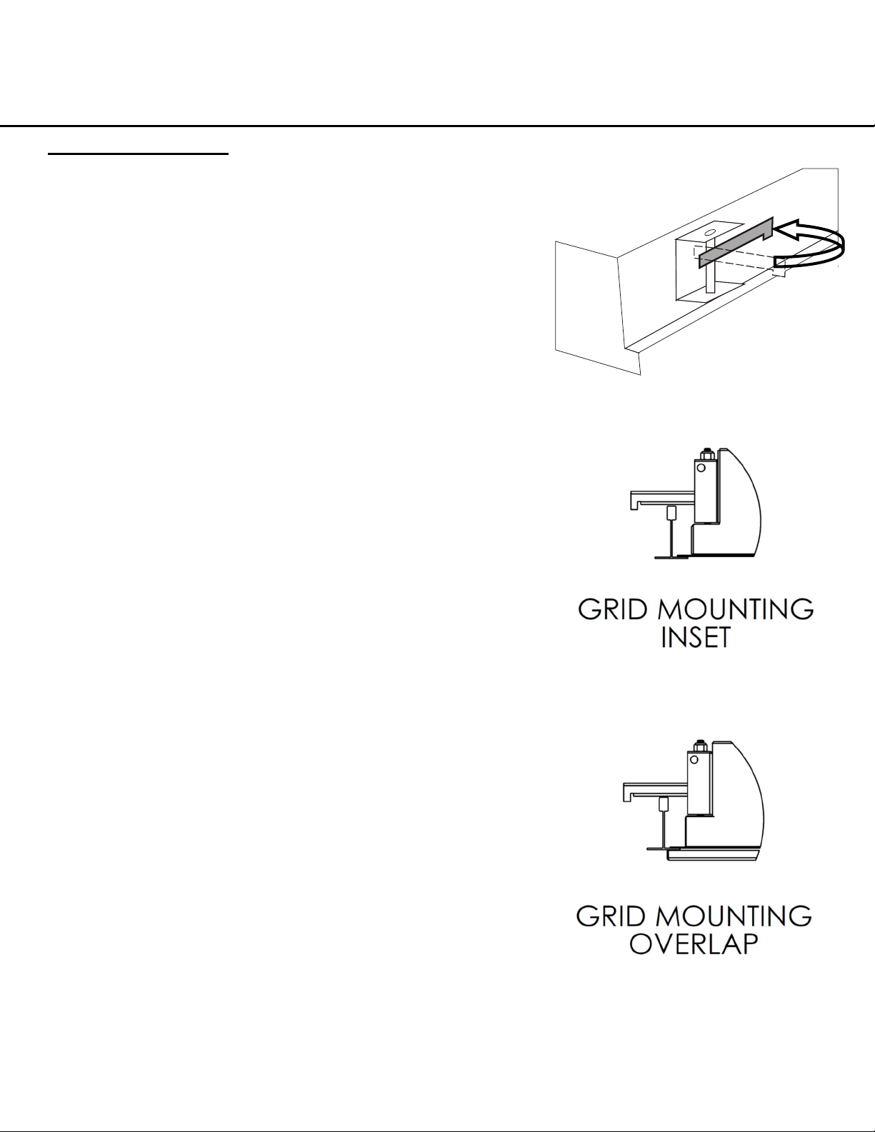
5. Insert the luminaire into the ceiling then extend the swing-out brackets above the support structure. Tighten all swing-
out brackets to ensure a tight and continuous seal on the room side of the opening.
6. Remove the cover and make the electrical connections to the power supply. Do not remove or use a different power
cord fitting than the one supplied.
7. Replace the cover and install suitable lamps (not supplied).
8. Replace the lens and door assembly with the original self-sealing screws. Tighten to a maximum torque of 10 in-lbs.
Ensure that the door gasket makes a continuous seal to the ceiling surface.
9. Apply power.
See next page for diagram
- Refer to sheet IIS00262 for Gasket Installation.

Page 3
MSU-DFX SERIES
Installation Instruction
ERP: IIS00344
03/11/2022 Rev1.0
Hard Ceiling Flange Cont’d
Size Width Length
2x2 22-7/8 in. 22-7/8 in.
2x4 22-7/8 in. 46-7/8 in.
Ceiling Cut-Out Dimensions:
Frame (not supplied)
1-5/8” Unistrut (or equal)
Ceiling cut-out
Swing-out Support Brackets
(4-pcs)
Width
Length

Page 4
MSU-DFX SERIES
Installation Instruction
ERP: IIS00344
03/11/2022 Rev1.0
Recessed Grid (T-Bar)
1. With fixture body resting face up on a stable surface, open doorframe
and remove internal reflector(s).
2. Removal of door hinge cable from housing is advised. Slide cable
through slot to disconnect door from housing. Set door aside in a
clean, safe place.
3. Locate provided power entry hole for supply connection.
4. A: For Hazardous Locations: Attach provided ½” Hub to hole from
outside being sure that the gasket mates with the outer surface of the
fixture. Tighten securely to housing using the nut provided. (Use only
the one (1) hub provided. ) Conduit and seal-offs are not provided
and may be required.
B: For ordinary locations: Create the supply entrance by securing
a conduit fitting to ½” trade size hole.
5. Remove all debris from the inside of the fixture.
6. Prepare a mounting means capable of reliably supporting more than
the weight of the fixture according to applicable building codes. Ceil-
ing Grid size is standard for 1” & 1.5” T-bar. Please specify other siz-
es when ordering.
7. Invert fixture and insert through ceiling opening and lay fixture cen-
tered on T-Bar. (For cleanrooms, verify that the grid has a gasket that
will contact the fixture flange. ) This step may require two workers.
8. Adjust mounting Swing-out support bracket(s) on housing to overlap
T-bar and support fixture on center web of T-bar. Tighten ¼-20
screws to transfer weight to T-bar, making sure gasket is com-
pressed and grid is level, without deformation.
9. Secure to structure using seismic support cables/wires to holes on
Swing-out support brackets. (Consult local code for requirements for
your geographic area.)
Note: This and all other hardware should be plated or stainless steel
if installed in a wet or damp location.
10. Rough in supply conduit and connections according to the NEC/CEC
and local requirements using minimum 90C supply wiring materials.
11. Connect grounding conductor to fixture grounding point.
12. Remove any protective films from the lens or surfaces as provided.
13. Replace reflector and secure by tightening screws or nuts.
14. If doorframe hinge cables were disconnected, reattach at this time.
(Note: Cable supported doors are reversible. )
15. Align door with housing and start screws by hand, being careful not
to cross-thread screws. Start process at two opposite corners for best
results.
16. Tightly secure doorframe using a hand screwdriver.
a. Do not overtighten. Maximum 10 inch-pounds torque.
b. Ensure that the door gasket makes a continuous seal to the
ceiling t-bar surface (overlapping door style) or fixture housing
(inset door style).
17. Energize fixture with rated voltage from a protected branch circuit.
Table of contents
Other Leviton Lantern manuals
Popular Lantern manuals by other brands

Robert Juliat
Robert Juliat SULLY 305L manual

Gama Sonic
Gama Sonic GS-5 instruction manual

Home Zone Security
Home Zone Security ELJ6539V installation instructions

Vaughan
Vaughan Valencay installation guide

Learning Resources
Learning Resources Primary Science LER 2763 user guide

Portfolio
Portfolio VEL-087-6W-PIR instructions