AECO SC30P-RE25 T AD3 User manual

8. Istruzioni per il collegamento
5. Installazione e messa in servizio
-25° ÷ +60°C
6. Istruzioni per l’installazione e il montaggio
10. Manutenzione e Riparazione
2. Identificazione del sensore
2.2 Diagramma codice
7. Etichettatura
web: www.aecosensors.com
Gruppo Categoria Tipo di
protezione
Gruppo di
esplosione
II 3D Ex tc IIIC T85°C -25 ÷ +60°C
Temperatura
Ambiente Ta
Modelli
I requisiti delle seguenti Norme sono soddisfatti:
1. Introduzione
3. Uso conforme
Marcatura Tipo di Atmosfera
Modelli
II 3D Ex tc IIIC T85°C Dc X
POLVERE
Istruzioni per l’uso
Conforme alla Direttiva 2014/34/UE (ATEX)
Allegato VIII, gruppo II, categoria apparecchi 3D
FC020EX Rev. FETC000284
Via G. Leopardi n°5-20065-Inzago (MI)-Italia /
IT
2.1 Diagramma descrizione
XResistenza all’impatto secondo EN60079-0:=E 4J=
Questo documento deve essere letto e compreso in tutte le sue parti prima
di procedere con l’installazione del sensore. I Sensori Capacitivi della
serie , sono adatti per essere utilizzati in
atmosfera potenzialmente
"SC30P-RE25 T AD3 "■ ■ ■
esplosiva dovuta alla presenza di POLVERI.
Questo sensore può essere usato in area pericolosa in accordo alla
classificazione:
Max Temp.
Superficiale
Il sensore non necessità di manutenzione e non deve essere
modificato. In caso di guasto non provare a ripararlo, ma rivolgersi al
servizio assistenza di AECO srl.
Se necessario possono essere richiesti ad AECO srl, o scaricati dal sito
web i seguenti documenti:
www.aecosensors.com,
Il sensore deve essere installato, connesso e attivato solo da personale
specializzato. Tale personale deve avere familiarità con i tipi di protezione
antiaccensione, le norme e i regolamenti per i mezzi di produzione nelle
zone a rischio di esplosione. L’utilizzatore è il solo responsabile della scelta
e l’uso del sensore adatto per l’applicazione finale. Verificare che la
classificazione sia idonea allo specifico caso d’impiego (vedi
‘’MARCATURA’’al par. 4 e il contrassegno sul dispositivo).
•
•
•
•
•
•
•
Proteggere efficacemente il cavo del sensore contro eventuali danni
rispettando le prescrizioni della norma EN60079-14;
Evitare di esporre le parti plastiche del sensore ai raggi (luce
solare).
Non montare il sensore nel flusso di polvere;
Evitare gli accumuli di polvere sul sensore e sul cavo;
Proteggere la parte sensibile del sensore dagli urti;
Le istruzioni per il collegamento del sensore e i relativi parametri
elettrici vanno desunti dal contrassegno e/o dalla scheda tecnica.
Vedi anche il par. 8;
La massima temperatura ambiente permessa nel luogo di
installazione deve sere compresa nel range:
UV
•
•
Scheda Tecnica del sensore.
Dichiarazione UE di Conformità.
I modelli di sensore di questa serie sono identificati con una '' ''
ed un '' ''. I relativi diagrammi di decodifica sono quelli mostrati al
paragrafo 2.1 e 2.2 .
Descrizione
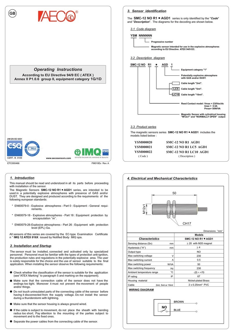
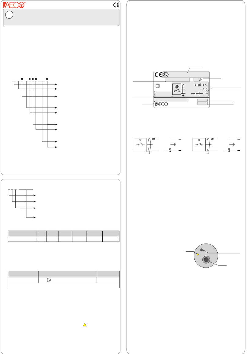
Codice Su ogni sensore è applicata l’ etichetta di prodotto come quella mostrata
in fig.7.1
Fig. 7.1 - Etichetta di prodotto
La figura 8.1 mostra lo schema di collegamento da utilizzare per tutti i
modelli della serie.
Quando si effettua l’installazione del sensore osservare i seguenti requisiti:
Attenersi alle norme e alle disposizioni nazionali vigenti, nonché alle
rispettive disposizioni diAECO srl;
Per evitare il formarsi di cariche statiche sulle parti plastiche e sul cavo
pulire il sensore con un panno umido;
Collegare a terra lo schermo del cavo del sensore;
•
•
•
4. Marcatura
SC30P-RE25 T AD3■■ ■
!
Fig. 8.1-Schema di collegamento
Y C 3 NNNNNN
Progressivo numerico
Dimensione custodia:
3: Filettata M30x1.5
Sensore conforme Direttiva 2014/34/UE(ATEX)
Sensore Capacitivo
9. Istruzioni per la taratura
Eseguire la regolazione della sensibilità con il sensore installato nella sua
posizione d’installazione finale dopo avere coperto circa il 70% della sua
parte sensibile con il materiale da rilevare. Quindi alimentare il sensore ed
effettuare le seguenti regolazioni:
- Se il LED è acceso ruotare il trimmer P1 in senso antiorario fino ad
ottenerne lo spegnimento. Successivamente ruotare ancora P1 in
senso orario fino a quando il LED si riaccende.
- Se il LED è spento ruotare il trimmer P1 in senso orario fino ad ottenerne
l’accensione.
Avviare l’impianto e verificare la corretta attivazione del sensore.
Eventualmente eseguire piccoli aggiustamenti della taratura fino ad ottenere
le regolazione desiderata.
Nel caso in cui il sensore è alloggiato in una sede metallica, quest’ultima
dovrà essere connessa a terra.
Attenzione !
Fig. 9.1 - Regolazione sensibilità
SC30
Dimensioni custodia:
-R
Versione:
E: Parzialmente schermato
Distanza di intervento(Sn) in mm
AD3
Apparecchio di categoria 3 per POLVERI
Lunghezza cavo:
Nullo: 3m
LCn: n
> 3m
lunghezza pari a “ ”m
se la lunghezza è
Sensore Capacitivo
Tipo di uscita:
30: Filettata M30x1.5
R: Relè in scambio
Materiale custodia
P: Plastica
P E 25 T
Temporizzato
Funzione di uscita:
A: Funzione ‘’A’’
B: Funzione ‘’B’’
Gamma temporizzazioni
1': 0.1sec ÷ 1min
10': 1sec ÷ 10min
REGOLAZIONE
SENSIBILITA’
LED
CAVO
P1 0
50
100
REG. TEMPO
SC30P-RE25 T AD3■■ ■
T75°C
T75°C
MARRONE
BIANCO
ROSSO
NERO
BLU
SCHERMO
NO
NC
COM
EN IEC 60079-0:2018-07+AC:2020-02 - "Atmosfere esplosive - Parte 0:
Apparecchiature - Prescrizioni generali".
"Atmosfere esplosive - Parte 31: Apparecchiature con
modo di protezione mediante custodie «t» destinati ad essere utilizzati in
presenza di polveri combustibili".
EN 60079-31:2014-07 -
Modello
Marcatura
Grado IP
Schema di collegamento
Lotto di produzione
Parametri elettrici
Imax=1A 220Vac
SUPPLY VOLTAGE
12 ÷ 240 Vac/dc
BROWN
BLUE
BLACK
WHITE
RED
T75°C
T75°C
NO
C
NC
II 3D Ex tc IIIC T85°C Dc X
Inzago - MI - Italy
IP67
Tamb : - 25°C Ta 60°C≤ ≤
Shield
00000
SC30P-RE25 T AD3■■ ■
Temperatura
ambiente
Anno di produzione
0000

5. Installation and set up
8. Wiring instructions
-25° ÷ +60°C
6. Installation remark
2. Sensor identification
2.2 Part number diagram
7. Labelling
web: www.aecosensors.com
Group Category Metod of
protection
II 3D Ex tc IIIC T85°C -25 ÷ +60°C
Models
1. Introduction
3. Compliant use
Marking
Models
II 3D Ex tc IIIC T85°C Dc X
DUST
Conforming to 2014/34/UE Directive (ATEX)
Annex VIII, group II, equipment category 3D
FC020EX Rev. FETC000284
2.1 Description diagram
XResistance to impact according to EN60079-0:= E 4J=
This document should be read and understood in all its parts before
proceeding with installation of the sensor. The Capacitive Sensors of the
series"SC30P-RE25 T AD3 "■ ■ ■ , are suitable for use in potentially
explosive atmospheres due to the presence of DUST.
This sensor can be used in hazardous area according to the classification:
The sensor does not need maintenance and should not be modified. In
case of fault do not try to repair it, but contact the customer care ofAECO
srl.
If necessary can be requested at AECO srl or downloaded from the
website the following documents:
www.aecosensors.com
•
•
•
•
•
•
•
Protect, efficiently, the sensor cable against damage by meeting the
requirements of the standard EN 60079-14;
Avoid exposing the plastic parts, of the sensor, to the direct radiation
with components (sunlight);
Do not mount the unit in the dust flow;
Avoid dust deposits on the sensor and its cable;
Protect the sensitive part of the sensor against impact;
For the wiring diagramm and the electrical technical data please see
the sensor mark and/or the techinical data sheet. See also par. 8;
The maximum ambient temperature permitted in the installation site
must be in the range:
UV
•
•
Sensor Data Sheet;
EU Declaration of Conformity;
On each sensor is applied a product label as shown in fig.7.1:
Fig. 7.1 - Product label
Figure 8.1 shows the wiring diagram to be used for all models in the
series.
When installing the sensor observe the following requirements:
Adhere to the relevant national regulations and provisions,as well as their
respective provisions of theAECO srl;
In order to avoid elettrostatic charging on the plastic parts and cable,
clean the sensor with a wet cloth only;
Always connect to earth the cable shield of the sensor;
•
•
•
4. Marking
!
Operating Instructions
Via G. Leopardi n°5-20065-Inzago (MI)-Italy /
GB
The sensors of this series are identified with a and a
. The related decoding diagrams are those shown in paragraph
2.1 and 2.2.
''Description'' ''Part
number''
Max Surface
Temperature
Explosion
group
Ambient
Temperature Ta
The requirements of the following stadards are met:
Atmosphere type
10. Maintance and Repair
The sensor must be installed, connected and activated only by specialized
personnel. Such personnel must be familiar with the types of protection
anti-ignition, the production rules and regulations in the potentially
explosive area. The user is solely responsible for the choice and the use of
the sensor suitable to the final application. Check whether the classification
of the sensor is suitable for the application (see ‘’Marking’’ to paragraph 4
and mark on the equipment).
Progressive number
Housing dimension:
Sensor conforming to 2014/34/EU directive (ATEX)
Y C 3 NNNNNN
3: Threaded M30x1.5
Capacitive sensor
Perform sensitivity adjustment with the sensor installed in its final installation
position after covering approximately 70% of its sensitive part with the
material to be detected. Then power on the sensor and make the following
adjustments:
- If the LED is on, turn the trimmer P1 counterclockwise until it is turned off.
Then turn P1 clockwise until the LED turns on again.
- If the LED is off, turn the P1 trimmer clockwise until it is switched on.
Start the system and verify the correct activation of the sensor. If necessary,
make small calibration adjustments until the desired adjustment is made.
In the case in which the sensor is stayed in a metal seat, the latter will be
connected to the ground.
Warning !
9. Instruction for sensing adjunstement
Fig. 9.1 - Sensitivity adjustment
SC30P-RE25 T AD3■■ ■
SC30P-RE25 T AD3■■ ■
Fig. 8.1- Wiring diagram
Housing dimension:
Equipment category 3 for DUST
Cable length:
Capacitive Sensor
30: M30x1.5Threaded
Blank: 3m
Lcn: length equal to “ ”m
if the lenght is
n
> 3m
Housing material:
Version:
E: Not Embeddable
Sensing distance(Sn) in mm
Output type:
R: Changeover relay
P: Plastic
SC30 -R AD3P E 25 T
Delayed
Output function:
A: Function ‘’A’’
B: Function ‘’B’’
Delayed range
1': 0.1sec ÷ 1min
10': 1sec ÷ 10min
SENSITIVITY
ADJUSTMENT
CABLE
LED
P1 0
50
100
TIME ADJ.
T75°C
T75°C
BROWN
WHITE
RED
BLACK
BLUE
SHIELD
NO
NC
COM
EN IEC 60079-0: 2018-07 + AC:2020-02
"Explosive atmospheres - Parte 0: Equipment - General requirements".
EN 60079-31: 2014-07
"Explosive atmospheres - Part 31: Equipment dust ignition protection by
enclosure «t»".
Model
Marking
IP grade
Wiring diagram
Production batch
Electrical parameter
Imax=1A 220Vac
SUPPLY VOLTAGE
12 ÷ 240 Vac/dc
BROWN
BLUE
BLACK
WHITE
RED
T75°C
T75°C
NO
C
NC
II 3D Ex tc IIIC T85°C Dc X
Inzago - MI - Italy
IP67
Tamb : - 25°C Ta 60°C≤ ≤
Shield
00000
SC30P-RE25 T AD3■■ ■
Ambient
temperature
Production year
0000

FIRMA
CONTR.
APPR.
SCALA
DATA
REV.
CODICE
FILE
SOSTITUISCE :
N° DIS. FC020EX
TIPO DI DOCUM. :
DESCRIZIONE
IMPIEGO
RAECO s.r.l. - via G. Leopardi, 5 20065 Inzago (MI) Italy
Tel. 02-954381 Fax 02-9548528
http : // www.aecosensors.com
.
Mod. XM007 - Rev. C 14.06.01
Pag. di3 3
F. Dayan
DOCUMENTAZIONE DI PRODUZIONE
ISTRUZIONI OPERATIVE ATEX
SENSORI CAPACITIVI
SERIE SC30P-RE25 T AD3■■ ■ C.d.M.
FC020EXF . CDR
REV. E
02.10.23
.
ETC000284
F
K23076EX
F. Capitanio
=
=
=
LINEE DI PIEGA
=
1. Introduction
This manual should be read and understood in all its parts before
proceeding with installation of the sensor.
The Magnetic Sensors SMC-12 NO SS BC HF LC. AGD2 series, are intended
to be used in a potentially explosive atmospheres with presence of GAS and/or
DUST. They are designed and produced according to the requirements of
the following european standards:
* EN60079-0 - Explosive atmospheres - Part 0 : Equipment - General requi-
rements.
* EN60079-18 - Explosive atmospheres - Part 18 : Equipment protection by
encapsulation ‘’m’’.
* EN60079-26-Explosive atmospheres - Part 26 : Equipment with protection
level (EPL) Ga.
All sensors of this series are covered by the EC-type Examination Certificate
n ° IMQ 12 ATEX016X issued by Notified Body IMQ spa.
2. Installation and Startup
The sensor mustbe installed, connected and activated only by specialized
personnel. Personnel must be familiar with the types of protection
anti-ignition, the production rules and regulations in the potentially explosive
area. The user is solely responsible for the choice and the use of sensor
suitable to the final application. When installing the sensor observe the
following requirements:
Check whether the classification of the sensor is suitable for the application
(see‘’ATEX Marking’’ to paragraph 5 and marking on the equipment).
Make sure that the connection cable of the sensor does not have the
endings too tight. Moreover it must not prevent the movementof people
and/or things.
Do not touch uninsulated parts of the connecting cable of the sensor before
having it disconnectedfrom the supply voltage.Do not install the sensor
during a thunderstorm with lightning.
Always connect the cable shield to the ground.
If the cable is subject to movement, do not place the sheath with bending
radius too short; Payattention to the mounting of the parties subject to
movement and to the fixed ones.
Separate the power cables from the connecting cable of the sensor.
Make sure that the sensor housing is always ground wired.
4. Electrical and Mechanical Characteristics
Sensing distance (Sn)
Characteristics
Models
SMC-12 NO SS BC HF LC. AGD2
Hysteresis (’’H’’)
mm
%Sn
Max switching voltage
Ambient temperature range
IP rating
Housing material
Cable
V
A
W/VA
Hz
°C
IP
Output type
> 20 with M20 magnet
<10
NO
100
0.5
50
230
-25 ÷ +70
67
Stainless steel-AISI 316
2 x 24 AWG PUR/TPE HF shielded
Dimensions in ‘’mm’’
NO
RED
BLACK
SHIELD
WIRING DIAGRAM
2mt, 5mt or 10mt
Max switching current
Max switching power
Max switching frequency
FM006Ex
Rev. B
Operating Instructions
According to EU Directive 2014/34/EU ( ATEX )
Annex VIII group II, equipment category 3D
www.aecosensors.com
1 2 3
I FOGLIETTI DEVONO ESSERE CONSEGNATI RIPIEGATI COME DA SEQUENZA INDICATA
Potentially explosive atmosphere
with GAS and/or DUST.
PUR/TPE shielded cable - Halogen free
SMC-12 LC AGDNO
Housing material: Stainless steel-AISI316
2Cable length "2mt".
5Cable length "5mt".
Cable length "10mt".
10
2
Equipment category "2"
SS BC HF
Magnetic Sensor with cylindrical housing
"M12x1" and "NORMALLYOPEN" output
3. Sensor identification
3.2 Description diagram
Magnetic sensor intended for use in the explosive atmospheres
according to EU Directive ATEX 94/9/EC.
YSM NNNNNN
Progressive number
3.1 Code diagram
3.3 Product series
( Description )
SMC-12 NO SS BC HF LC2 AGD2
( Code )
YSM000008
SMC-12 NO SS BC HF LC5 AGD2
YSM000009
SMC-12 NO SS BC HF LC10 AGD2
YSM000010
The magnetic sensors series includes
the models listed below:
SMC12-NO SS BC HF LC. AGD2
The series is only identified by the
'' '' and '' ''. The diagrams for the decoding are shown below.
SMC12-NO SS BC HF LC. AGD2
Code Description
Operating Instructions
According to Directive 2014/34/EU ( ATEX )
Annex II P 1.06 group II, equipment category 1G/1D
www.aecosensors.com
web: www.aecosensors.com
Istruzioni per l’uso
Conforme a:
Direttiva UE 94/9 CE (ATEX)
Allegato II P1.0.6 gruppo II, categoria apparecchi 1G/1D
■
Sistema di certificazione IECEx■
Via G. Leopardi n°5 - 20065 Inzago (MI) /
IT
5. Schema di collegamento
Table of contents
Languages:
Other AECO Security Sensor manuals
