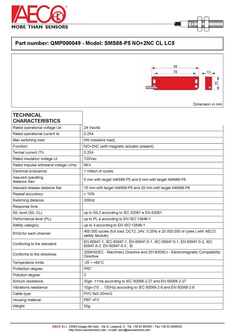
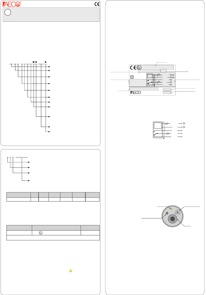
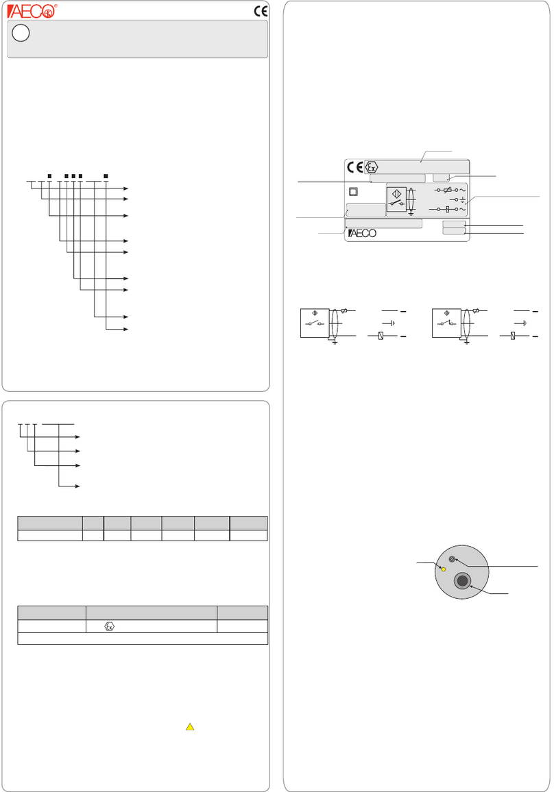
AECO SMC-12 NO R1 AGD1 User manual

www.aecosensors.com
YSM NNNNNN
SMC-12 NO R1 AGD1
YSM000020
SMC-12 NO R1 LC5 AGD1
YSM000021
SMC-12 NO R1 LC10 AGD1
YSM000022
SMC-12 NO R1 AGD1■
mm
mm
V
A
W/VA
Hz
°C
IP
> 4
NO
230
0.5
50
230
-25 ÷ +70
67
2 x 0.25mm² PVC
FM010Ex Rev. A
50
CH17
M12x1
NO
SMC-12 NO AGD
LC10
1R1
LC5
ETC000466
BLUE
BROWN
Sensing distance (Sn)
Hysteresis (’’H’’)
Max switching voltage
Ambient temperature range
IP rating
Housing material
Cable
Output type
Max switching current
Max switching power
Max switching frequency
> 20 with M20 magnet
Nickel-plated Brass
2mt, 5mt or 10mt
WIRING DIAGRAM
Characteristics
Models
Dimensions ‘’mm’’
4. Electrical and Mechanical Characteristics
( Description )( Code )
3.3 Product series
The magnetic sensors series includes the
models listed below :
SMC-12 NO R1 AGD1■
Potentially explosive atmosphere
with GAS and/or DUST.
Reed Contact model: Vmax = 230Vac/dc
Imax = 0.5A
Pmax= 50W/VA
Cable length "2mt".
Cable length "5mt".
Cable length "10mt".
Equipment category "1"
Magnetic Sensor with cylindrical housing
"M12x1" and "NORMALLY OPEN" output
3.2 Description diagram
3.1 Code diagram
Magnetic sensor intended for use in the explosive atmospheres
according to EU Directive ATEX 94/9 EC.
Progressive number
3. Sensor identification
The series is only identified by the '' ''
and '' ''. The diagrams for the decoding are shown below.
Code
Description
SMC-12 NO R1 AGD1■
1. Introduction
This manual should be read and understood in all its parts before proceeding
with installation of the sensor.
The Magnetic Sensors series, are intended to be
used in a potentially explosive atmospheres with presence of GAS and/or
DUST. They are designed and produced according to the requirements of the
following european standards:
* EN60079-0 - Explosive atmospheres - Part 0 : Equipment - General requi-
rements.
* EN60079-18 - Explosive atmospheres - Part 18 : Equipment protection by
encapsulation ‘’m’’.
* EN60079-26-Explosive atmospheres - Part 26 : Equipment with protection
level (EPL) Ga.
All sensors of this series are covered by the EC-type Examination Certificate
n ° issued by Notified Body IMQ spa.IMQ 12 ATEX 016X
SMC-12 NO R1 AGD1
■
2. Installation and Startup
The sensor must be installed, connected and activated only by specialized
personnel. Personnel must be familiar with the types of protection anti-ignition,
the production rules and regulations in the potentially explosive area. The user
is solely responsible for the choice and the use of sensor suitable to the final
application. When installing the sensor observe the following requirements:
Check whether the classification of the sensor is suitable for the application
(see‘’ATEX Marking’’ to paragraph 5 and marking on the equipment).
Make sure that the connection cable of the sensor does not have the
endings too tight. Moreover it must not prevent the movement of people
and/or things.
Do not touch uninsulated parts of the connecting cable of the sensor before
having it disconnected from the supply voltage. Do not install the sensor
during a thunderstorm with lightning.
If the cable is subject to movement, do not place the sheath with bending
radius too short; Pay attention to the mounting of the parties subject to
movement and to the fixed ones.
Separate the power cables from the connecting cable of the sensor.
Make sure that the sensor housing is always ground wired.
Operating Instructions
According to EU Directive 94/9 EC ( ATEX )
Annex II P1.0.6 group II, equipment category 1G/1D
GB

Sig. M. Scaramuzza
Fig. 1
BROWN
BLUE
SMC-12 NO R1 AGD1■
V= 230V I= 0.5A P= 50W/VA
Tamb: -25 ÷ +70°C
IMQ 12 ATEX 016X
88888
0722
II 1G Ex ma IIC T6 Ga
II 1D Ex ma IIIC T85°C Da IP67
AECO Inzago-MI-Italy
Fig. 2
DIC14014EX REV. 01
II 1D Ex ma IIIC T85°C Da IP67
II 1G Ex ma IIC T6 Ga Ta= -25 ÷ +70°C
0722
YSM000020
YSM000021
YSM000022
SMC-12 NO R1 AGD1
SMC-12 NO R1 LC5 AGD1
SMC-12 NO R1 LC10 AGD1
NO
Fp Fp
Via G. Leopardi 5 - 20065 Inzago ( MI ) Italia
Inzago: 2014/10/31
( Place and Date )
( Name and Signature )
( Description )( Code )
2006/95/CE - Low Voltage Directive
94/9/EC - ATEX Directive - GROUP CATEGORY EXPLOSIVE ATMOSPHERES
WITH PRESENCE OF GAS AND/OR THE
PRESENCE OF DUST
“II”
“G” ( )
“D” ( )
’’1”
ZONE 0
ZONE 20
MARKING :
( Title and / or number and date of issue of the standard )
according to the provisions of the European Directives:
EN 60079-0
August 2009
EN 60947-1
July 2007
EN 60947-5-1
June 2004
EN 60079-26
March 2007
EN 60079-18
December 2009
to which this declaration relates are in conformity with the following standards:
declare under our sole responsibility that the products:
(Product’s name )
MAGNETIC SENSORS
DECLARATION OF CONFORMITY
9. Declaration of Conformity
We, AECO s.r.l.
( Supplier’s name )
( Supplier’s address )
8. Maintenance
The sensor has no serviceable components and can not be changed and / or
repaired. In case of failure, please contact AECO srl customer service.
If necessary, you can ask AECO srl for a copy of the following documents :
Sensor Data Sheet
Declaration of Conformity
EC-Type Examination Certificate
You can also download the same documents from AECO web site
( ).
www.aecosensors.com
Production batch
ATEX Marking
EC-Type Examination
Certificate number
Ambient temperature range
‘’Model’’ description
Electrical parameters
Wiring diagram
7. Labelling
On every sensor of the '' ''
is applied as shown in Fig. 2 :
SMC-12 NO R1 AGD1■series a label
BROWN
BLUE
Signal
Signal
Sensor Field
If the non resettable fuse complies with IEC 60127 series or
IEC 60691 or ANSI/UL 248-1 only one fuse is necessary.
Protection Fuse
Fp =
Inf (A)= 1A
(Fuse nominal current)
Vnf (V)=230Vac
(Fuse nominal voltage)
Rupture capacity
1500A
Temperature class for GAS
Indicates the maximum surface temperature that can reach the sensor
at the maximum ambient temperature according to EN60079-0.
T6 Maximum surface temperature : 85 ° C
Maximum Surface Temperature for DUST
Indicates the maximum surface temperature that can reach the sensor
at the maximum ambient temperature according to EN60079-0.
T85 Maximum surface temperature : 85 ° C
Equipment Protection Level (EPL) for GAS
Indicates the level of protection of the equipment according to
:EN60079-18
Ga Equipment with protection level ' 'ma
Equipment Protection Level (EPL) for DUST
Indicates the level of protection of the equipment according to
:EN60079-18
Da Equipment with protection level ' 'ma
6. Conditions of use in potentially explosive area.
During the use of the sensor in potentially explosive atmosphere observing
the following instructions is important for safety :
The maximum permissible ambient temperature is Ta = +70 °C
To protect the sensor from damage due to shock and vibration
It is necessary to protect the circuit by connecting in series to the sensor
2 non resettable fast-acting fuses with the following ratings :
5. ATEX marking
II 1D Ex ma IIIC T85°C Da IP67
II 1G Ex ma IIC T6 Ga
ZONE 0, ZONE 1 and ZONE 2 (Atmosphere with GAS)
ZONE 20, ZONE 21 and ZONE 22 ( DUST)Atmosphere with
for use in
For all models '' '' refere to the ATEX
marking below indicated :
SMC-12 NO R1 AGD1■
The meaning of the symbols that make the marking is as follows:
Specific mark. Protection against explosion
II
Equipment group.
Category group.
1Equipment designed for use in places where
(ZONE 0 or ZONE 20).
an explosive atmosphere
is constantly present
Equipment suitable for use in all other places other than mines and
their surface installations.
GAtmosphere due to the presence of , and .gases vapors mists
DAtmosphere due to the presence of dust
Ex Equipment designed for use in potentially explosive atmospheres
Type of explosive atmosphere
ma
Type of protection
Encapsulation protection level according to .EN60079-18''ma''
Explosion group GAS
Specifies the explosion group wich the type of GAS belongs to,
according to EN 60079-20.
IIC The typical GAS of this group is the hydrogen
Explosion group DUST
IIIC Conductive dust
Specifies the explosion group wich the type of DUST belongs to,
according to EN 60079-0.
This manual suits for next models
5
Other AECO Security Sensor manuals
Popular Security Sensor manuals by other brands
olympia electronics
olympia electronics BSR-6060/A/MAR instruction manual
Powerfix Profi
Powerfix Profi PMDL 5 B1 operating instructions
Meec tools
Meec tools 010986 operating instructions
Ortus
Ortus PIR-R Operation manual
SImx
SImx LHT0142 installation manual
MDT Technologies
MDT Technologies VisuControl Easy II operating instructions
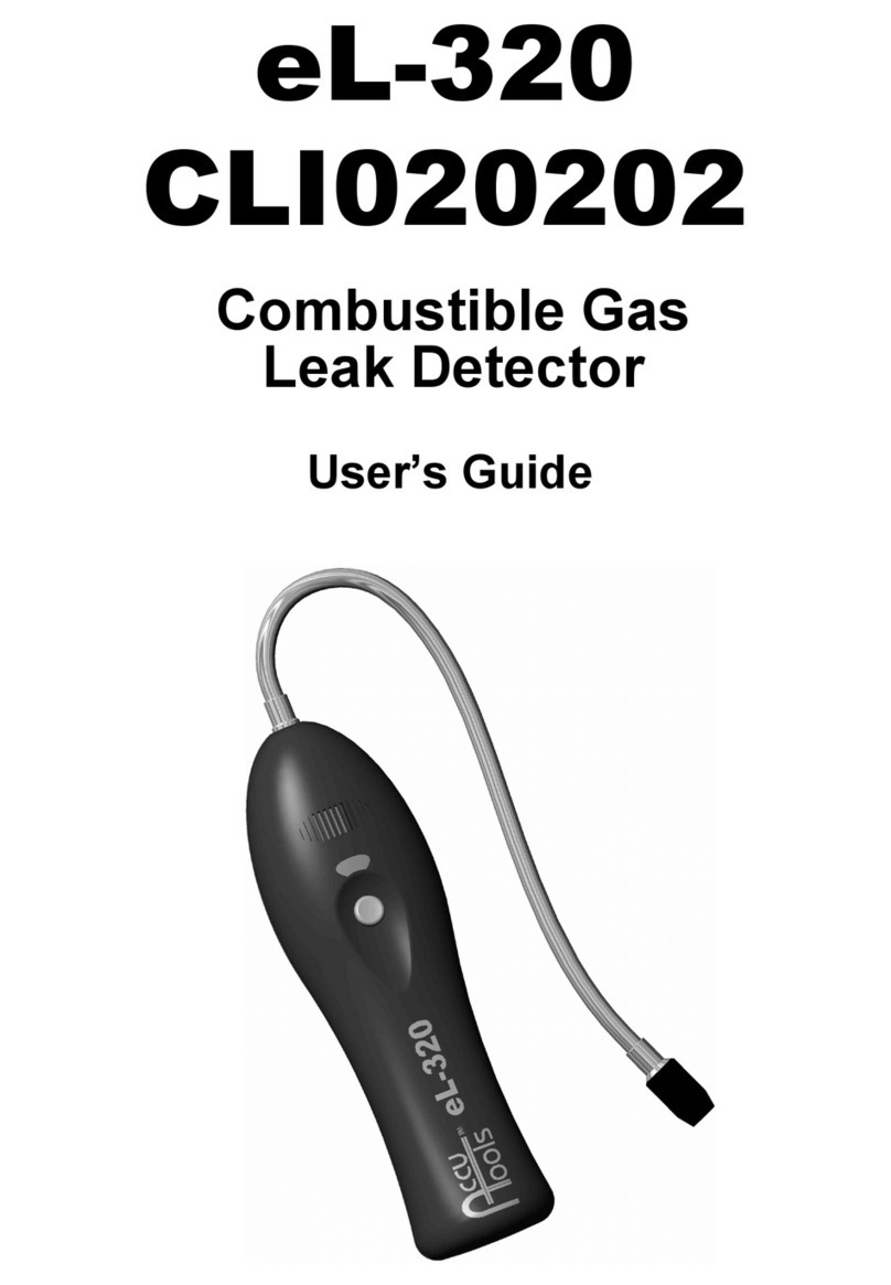
AccuTools
AccuTools eL-320 user guide
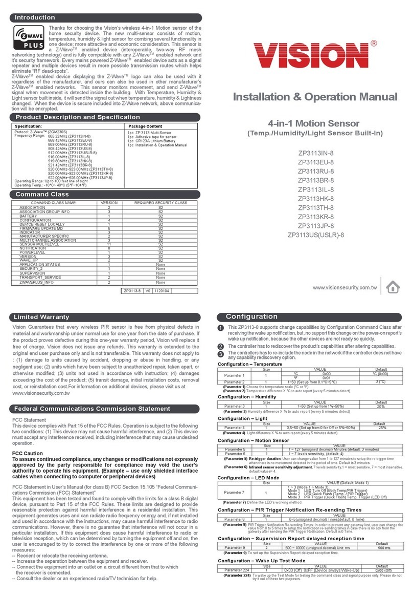
Vision
Vision ZP3113IN-8 Installation & operation manual
Leuze
Leuze MLD 300 operating instructions

Sonel
Sonel VT-2 instruction manual
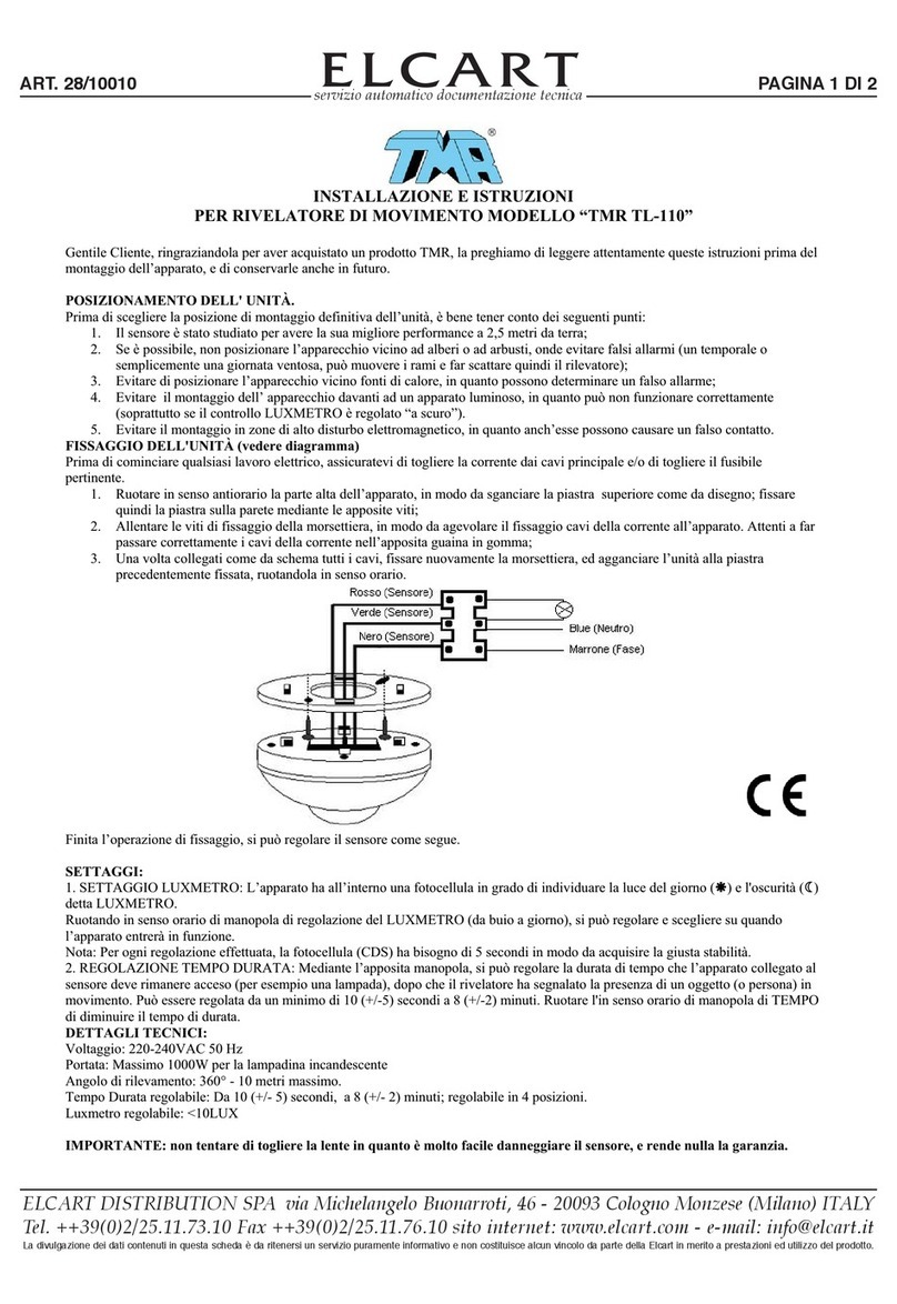
ELCART
ELCART TMR TL-110 Installation and operating instructions
Gems Sensors
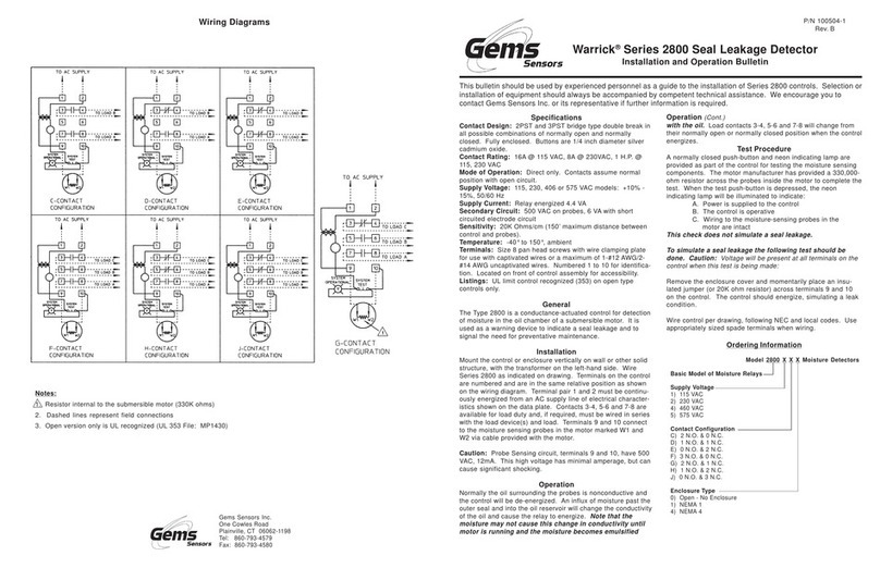
Gems Sensors Warrick 2800 Series Installation and Operation Bulletin

