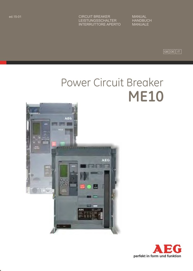
AEG ME09 Installation and operating instructions

ME09 空气断路器
5000-6400A
用户手册

ጀᅪƽዘᄲ༵๖
য়ߢ
&WTKPI QRGTCVKQP VJG FGXKEG FGUETKDGF KP VJKU
OCPWCN KU EQPPGEVGF VQ JKIJ CPF RQVGPVKCNN[
FCPIGTQWUXQNVCIGU
9JGP VJG EKTEWKV DTGCMGT KU UYKVEJKPI JKIJ
EWTTGPVU GURGEKCNN[ UJQTVEKTEWKV EWTTGPVU JQV
CPFKQPK\GFICUOC[DGGOKVVGF
1PN[SWCNKHKGFRGTUQPPGNCTGCNNQYGFVQKPUVCNN
EQOOKUUKQP OCKPVCKP QT OQFKH[ VJKU FGXKEG KP
CEEQTFCPEGYKVJTGNGXCPVUCHGV[TGSWKTGOGPVU
6JG%KTEWKV$TGCMGTOWUVDGGSWKRRGFYKVJVJG
CRRTQRTKCVG EQXGTU CPFQT DG KPUVCNNGF KP C
UWKVCDNGGPENQUWTGQTRCPGNVCMKPIVJGTGSWKTGF
UCHGV[ENGCTCPEGUKPVQCEEQWPV
0QP%QORNKCPEGYKVJVJGUGTGSWKTGOGPVUEQWNF
TGUWNV KP FCOCIG VQ RTQRGTV[ CPFQT UGXGTG
KPLWT[VQRGTUQPPGN
Caution! Important Requirements!
য়ߢ༵๖ణ
Ԩ֩ዐ༵๖ڦยԢሞሏႜথ
٪ሞླ၃ڦߛუۉᇸă
ୟഗߛۉୁLjᆮഄ܌ୟۉୁ้Lj
ీׂࣷิߛ࿒ጱࣅഘ༹ă
ৈሎႹࢇ߭ටᇵӀቷ၎࠲Ҿඇᄲ൱ҾጎĂۙ
ĂྼႪ߀ጎԨยԢă
ୟഗՂႷದԢҾጎሞࢇڦ؊ݴ୯କ
Ҿඇဤڦࡋ௬ӱዐă
ٳփڟኄၵᄲ൱ీࣷڞዂ֎ׂ฿ࢅ0
ටᇵฅྨă
WARNING
൩ለ܁ժԍ٪Ԩ֩ᅜԢࢫ๑ᆩă Read this manual and please retain for future use.
ᆅჾ ୟഗ
ۉጱྃഗ
֪
INTRO BREAKER
TRIP UNIT
LOCKS ACCESSORIES TESTS APPENDIX
NF1:ဣଚگუഘୟഗ

The following important highlighted informaƟon appears
throughout this document to warn of potenƟal hazards or to
call aƩenƟon to informaƟon that clariĮes a procedure.
Carefully read all instrucƟons and become familiar with the
devices before trying to install, operate, service or maintain
this equipment.
ѷ
ҾጎĂ֡ፕྼࢺ֩
.&""ቇඡல٨
ԀᬗѬዝ
ಖ TRADEMARKS
InstallaƟon, OperaƟon and Maintenance
ME09 5000A-6400A Power Circuit Breaker
HAZARD CATEGORIES
Ԩ࿔ᇀഄӲ้ᆩڦ႑တă
்ᅙ૰ඓԍጨଙጚඓLjڍԨ࿔ዐԈࡤڦ႑တժ
փԈઔᆘࢅዐڦᆶၘဦ႑တࢅՎଉLjᄺփԈઔҾ
ጎĂ֡ፕࢅྼࢺࡗײዐీ၄ڦᆶᅪྔ๚ࠤă
Ԩ࿔ዐຫڦ༬ኙీփᆩᇀᆶᆘࢅဣཥă
Ԩ࿔සᆶ߸߀LjBFHփሴଷႜཚኪ࿔ᆶටă
ᇀԨ࿔ࡤ႑တޏጚඓĂྜኝĂ؊ݴᆩLjBFH
փፕඪࢆඓĂӁ๖݆ۨ๖څԍLjᄺփڅඪࢆሴ
ඪă
փڅԍԨยԢڦၨႠࢅᆩႠă
සႴᆶ࠲ୟഗ֡ፕྼࢺڦഄ႑တLj൩ဣԨںၨ
ևோă
Ԩ࿔ዐ၄ڦᅜူዘᄲ႑တྺକܔയሞླ၃༵য়ߢ
ᄲ൱܁ኁጀᅪຫ֡ፕײႾڦ႑တă
൩ሞҾጎĂ֡ፕĂྼႪྼࢺԨยԢമጮဦለ܁ᆶ
ຫժຄဒ߲߳ጎዃă
ၭ႐ǖփӀቷຫ֡ፕࣷڞዂׂă
ጀᅪǖُ֩ᆩᇀӻዺࢽ๑ᆩُยԢă൩ഄԍାLjᅜ
Ԣઠ๑ᆩă
Indicates a hazardous situaƟon which, if not avoided, could
result in death or serious injury.
CAUTION: Failure to comply with these instrucƟons may
result in product damage.
NOTICE: An aid meant to assist the user in performing the
set task. Please retain for future use.
This documen is based on informaƟon availableat the Ɵme of
its publicaƟon.
While eīor ts have been made to ensure accuracy, the
informaƟon contained herein does not cover all details or
variaƟons in hardware and soŌware, nor does it provide for
every possible conƟngency in connecƟon with installaƟon,
operaƟon, and maintenance.
Features may be described herein that are not present in all
hardware and soŌware systems.
AEG assumes no obligaƟon of noƟce to holders of this
document with respect to changes subsequently made.
AEG makes no representaƟon or warranty, expressed, implied,
or statutory, with respect to, and assumes no responsibility for
the accuracy, completeness, suĸciency, or usefulness of the
informaƟon contained herein.
No warrantees of merchantability or Įtness for purpose shall
apply.
Contact your local sales oĸce if fur ther informaƟon is required
concerning any aspect of 5000A-6400A circuit breaker
operaƟon or maintenance.
1.0 GENERAL INFORMATION
1.0
ຫ٪ሞڦླ၃ጒLjසփీՆ௨Lj
ࣷڞዂჹዘฅྨă
Ԁᬗἰ%"/(&3
য়ߢ
ᆅჾ
INTRO
1.0-01
NF1:ဣଚگუഘୟഗ

ᆅჾ ୟഗ
ۉጱྃഗ
֪
য়ߢ༵๖ణ
INTRO BREAKER
TRIP UNIT
LOCKS ACCESSORIES TESTS APPENDIX
2/1!!!!!!!ጺሶ
----------------------------------------------------------
2/2/1!!!!!ᆅჾ
!!!!!!!!!!ዊଉԍኤ
!!!!!!!!!!ֱ
!!!!!!!!!!ׂဣଚࡽ
!!!!!!!!!!֪ଉڇ࿋
2/2/2!!!!!ׂᄲຫ
2/2/3!!!!!༬ኙࢅ༬ۅ
2/2/4!!!!!ئ٪
2/2/5!!!!!ఀಈຫ
2/2/6!!!!!ҾጎႴ߾
------------------------------------------------------
2/3!!!!!!!ׂࡀ߭
!!!!!!!!!!.!
------------------------------------------------------
2/4!!!!!!!Ҿጎ
2/4/2!!!!!༵ืࢅҾጎ
!!!!!!!!!!༵ืכࢅದഗ
2/4/3!!!!!ࠦۨ๕ୟഗ
!!!!!!!!!!Ҿጎ
2/4/4!!!!!؏๕ୟഗ
!!!!!!!!!!Ҿጎ
!!!!!!!!!!ٗ؏ዐൽ
!!!!!!!!!!Ҿጎڟ؏ዐ
2/4/5!!!!!ْܾথ၍܋ጱ
!!!!!!!!!!࿋ዃ
!!!!!!!!!!ᆩ
!!!!!!!!!!!!ጺ
!!!!!!!!!!!!থڟ܋ጱӱ!B!ࢅ܋ጱӱ!C!ڦጎ
!!!!!!!!!!ዃڦۨᅭ
------------------------------------------------------
2/5!!!!!!!֡ፕ
2/5/2!!!!!ዷڑࣟئీ
!!!!!!!!!!!!!!!!!!!!ۯ
!!!!!!!!!!!!!!!!!!!!ۉۯ
2/5/3!!!!!֡ፕຩႾ
2/5/4!!!!!ୟഗԿࢇ֡ፕ
2/5/5!!!!!ୟഗ֡ፕ
2/5/6!!!!!ൽୟഗ
2/5/7!!!!!֭ୟഗ
2/5/8!!!!!֡ፕຩႾǖ؏
------------------------------------------------------
3/1!!!!!!!ۉጱྃഗ
!!!!!!!!!!ጺሶ
3/2!!!!!!!ׂຫ
3/3!!!!!!!֡ፕ
3/4!!!!!!!MDE!၂๖ೡఇ๕
3/5!!!!!!!൸၍
3/6!!!!!!!ཚ႑٪ഗ
3/7!!!!!!!Ҿጎ
3/8!!!!!!!থ၍
1.0 GENERAL INFORMATION
------------------------------------------------------
1.1.0 IntroducƟon
Quality Assurance
OpƟons Check Sheet
Product Serial Number
Measurement Units
1.1.1 Short Product DescripƟon
1.1.2 Features and CharacterisƟcs
1.1.3 Storage
1.1.4 RaƟng label descripƟon
1.1.5 Tools Needed for InstallaƟon
------------------------------------------------------
1.2 PRODUCT SPECIFICATIONS
- Tables
------------------------------------------------------
1.3 INSTALLATION
1.3.1 LiŌing and MounƟng
LiŌing Truck and Adapter
1.3.2 Fixed-PaƩern Circuit Breaker
InstallaƟon
1.3.3 Drawout PaƩern Circuit Breaker
InstallaƟon
Removal from CasseƩe
MounƟng in CasseƩe
1.3.4 Secondary Disconnect Terminal Blocks
LocaƟon
Use
Table -- General schemaƟcs
Table -- DeĮniƟon of connected devices
to Block A and Block B
------------------------------------------------------
1.4 OPERATION
1.4.1 harging of Main Springs
Manually
Electrically
1.4.2 Sequence of breaker operaƟon
1.4.3 Circuit breaker closing operaƟon
1.4.4 Circuit breaker opening operaƟon
1.4.5 Circuit breaker Withdrawal
1.4.6 Circuit breaker InserƟon/CasseƩe
1.4.7 Sequence of operaƟon casseƩe
------------------------------------------------------
2.0 TRIP UNIT
General InformaƟon
2.1 Product descripƟon
2.2 OperaƟon
2.3 LCD Screen Mode
2.4 Curves
2.5 CommunicaƟon Register
2.6 InstallaƟon
2.7 ConnecƟon scheme
1.0-2
ణ DPOUFOU
NF1:ဣଚگუഘୟഗ

1.0
য়ߢ
1.0-3
4/1!!!!!!!ࢅጎዃ
4/2!!!!!!!ୟഗമ௬ӱ
!!!!!!!!!!.!ୟഗࠬ
!!!!!!!!!!.!ୟഗሃ
!!!!!!!!!!.!Ӏ౧ۨ
4/3!!!!!!!؏
!!!!!!!!!!.!Ҿඇڔӱࠬ
!!!!!!!!!!.!ཉࠓࠬ
!!!!!!!!!!.!ڞࡆ
!!!!!!!!!!.!ோጎዃ
!!!!!!!!!!.!ሃ
!!!!!!!!!!.!֭๎՚ጎዃ
4/4!!!!!!!ୟഗᇑୟഗ
!!!!!!!!!!.!203!ୟഗ
!!!!!!!!!!.!204!ୟഗ
!!!!!!!!!!.!304!ୟഗ
!!!!!!!!!!.!304!ୟഗDŽᆶᆫံDž
4/5!!!!!!!ۉഘ၍ං
------------------------------------------------------
5/1!!!!!!!ຫ
!!!!!!!!!!ጺຫ
5/2!!!!!!!၍ං0֡ፕഗ
5/3!!!!!!!ۉۯ֡ፕഗ
5/4!!!!!!!ةۅ
5/5!!!!!!!ഄև
5/6!!!!!!!
5/7!!!!!!!Ԣ
5/8!!!!!!!Ҿጎ
------------------------------------------------------
6/1!!!!!!!ྼࢺĂ֪ࢅࠤቱಇأ
6/2!!!!!!!ྼࢺ
!!!!!!!!!!.!ֱ
6/3!!!!!!!ൣဢײႾ
!!!!!!!!!!.!௶ࢷةۅֱ
!!!!!!!!!!.!ୟഗዷᄲႁጎዃֱ
6/4!!!!!!!؏ֱ
6/5!!!!!!!ۉጱྃഗֱ
6/6!!!!!!!߰ةۅDŽ؏๕Džֱ
6/7!!!!!!!ۉᇸజಇֱ
6/8!!!!!!!ාࣂ
6/9!!!!!!!֪
!!!!!!!!!!.!ۉጱྃഗ֪
6/:!!!!!!!ࠤቱಇأ
------------------------------------------------------
7/1!!!!!!!
7/2!!!!!!!้ۉୁ൸၍
7/3!!!!!!!ణࡽຫ
7/4!!!!!!!٫
7/5!!!!!!!ޜခ
3.0 LOCKS AND INTERLOCKS
3.1 Circuit breaker front panel
- Breaker padlock
- Breaker Key Lock
- PushbuƩon locking
3.2 CasseƩe
- Safety shuƩer padlocking
- Racking access padlocking
- Rail Locks
- Door interlock
- Key locks
- Miss inserƟon device
3.3 Breaker to breaker Interlock
- 1 of 2 breaker interlock
- 1 of 3 breaker interlock
- 2 of 3 breaker interlock
- 2 of 3 breaker interlock with priority
3.4 Network Interlock
------------------------------------------------------
4.0 ACCESSORIES DESCRIPTION
General InformaƟon
4.1 Releases / Coils
4.2 Electrical Charging Motor
4.3 Contacts
4.4 InstallaƟon parts
4.5 Accessories
4.6 Spare parts
------------------------------------------------------
5.0 MAINTENANCE, TESTING AND
TROUBLESHOOTING
5.1 Maintenance
- InspecƟon Schedule
5.2 Cleaning Procedure
- Arcing Contacts InspecƟon
- Circuit Breaker Main Mechanism
InspecƟon
5.3 asseƩe InspecƟon
5.4 Contact wear InspecƟon
5.5 IsolaƟng Contacts (Drawout Type)
InspecƟon
5.6 Power Terminals and Busbar
InspecƟon
5.7 LubricaƟon
5.8 TesƟng
- Trip Unit TesƟng
5.9 TroubleshooƟng
------------------------------------------------------
6.0 APPENDIX
6.1 Time current curves
6.2 Catalogue number descripƟon
6.3 Dimension
6.4 Service
ᆅჾ
INTRO
NF1:ဣଚگუഘୟഗ

ᆅჾ ୟഗ
ۉጱྃഗ
֪
INTRO BREAKER
TRIP UNIT
LOCKS ACCESSORIES TESTS APPENDIX
2/2/1!!!!!!ᆅჾ
!!!!!!!!!!!䐫㑠⡄䐅
!!!!!!!!!!!䁂ミネ⥊⢎
!!!!!!!!!!!⥛㠘㻖㑱⼦
!!!!!!!!!!!⥃㑠⭆㸜
2/2/2!!!!!!ׂᄲຫ
2/2/3!!!!!!༬ኙࢅ༬ۅ
2/2/4!!!!!!ئ٪
2/2/5!!!!!!ఀಈຫ
2/2/6!!!!!!ҾጎႴ߾
!2/1ǖ6111B.7511Bኟ
B*!ኸ๖ഗ
C*!ئీդ
D*!ۉۯࢇቄDŽԿࢇDž
E*!ۯࢇቄDŽԿࢇDž
F*!ԿࢇڑࣟئీݣӀ౧
G*!PO0PGGDŽࢇቄ0ݴቄDžӀ౧ጒༀ
H*!PO0PGGDŽࢇቄ0ݴቄDžጒༀኸ๖ഗ
I*!ڑࣟئీጒༀ
J*!ୟഗܮۨኵ
K*!Spojt0Qspgbmvy!ሃ
L*!Dbtufmm!ሃ
M*!֡ፕຕഗ
N*!ጚԢࢇቄኸ๖
O*!ۯݴቄDŽDž
P*!ୟഗࠬ
Q*!ۉጱྃഗ
R*!ۯް࿋ۉഘ၍ං
1.1.0 IntroducƟon
Quality Assurance
OpƟons Check Sheet
Product Serial Number
Measurement Units
1.1.1 Short Product DescripƟon
1.1.2 Features and CharacterisƟcs
1.1.3 Storage
1.1.4 RaƟng label descripƟon
1.1.5 Tools Needed for InstallaƟon
Fig. 1.0: 5000A-6400A Front View
A) Accessory Indicator
B) Charging Handle
C) Electrical ON (Close)
D) Manual ON (Close)
E) Closing Spring Discharge BuƩon
F) ON/OFF PushbuƩon Status
G) ON/OFF Status Indicator
H) Spring Charge Status
I) Breaker RaƟng
J) Ronis/Profalux Key
K) Castell Key
L) OperaƟons Counter
M) Ready to Close
N) Manual OFF (Open)
O) Breaker Padlock
P) Trip Unit
Q) Manual reset for opƟonal Network Interlock
coil
1.1-1
䓃 QRWH
$
4
3
2
1
0
/
.
-
%
&
(
'
*
)
+
,
ᆅჾࡀ߭Ҿጎ֡ፕۉጱྃഗ
NF1:ဣଚگუഘୟഗ

1.1
ᆅჾ
1.1-02
ዊଉԍኤ
ᆶ!NF1:!ୟഗۼӀቷፌߛຍՔጚยࢅሰă
BFH!֑ᆩჹ߭ڦײႾඓԍٳڟภڦຍՔ
ጚժԍኤᅃୁڦׂዊଉă
ֱֱ
߲ୟഗۼᆶֱLjଚକୟഗĂ؏ࢅۉ
ጱྃഗDŽස۩ࠔDžԈࡤڦ༬Ⴀࢅă
ణࡽຫ
֖ă
ׂဣଚࡽ
ᇑ! BFH! ৽ԨยԢᆶ࠲๚ᅓႜࠏཚ้Lj൩ຫဣଚࡽă
߲ୟഗۼᆯᅃ߲༬ᆶڦဣଚࡽLj࿋ᇀᅜူଇ߲࿋ዃǖ
噝!ฦ༵ืڦۥև
噝!മ௬ӱፑ֨DŽٗኟ௬Dž
2/2/2!ׂᄲຫ
NF1:ഘୟഗྺഘୟഗLjยޙࢇ!
HC25159/3.3119ՔጚăԨ֩ጆᆩᇀޙࢇ! JFD0FO!
71:58!ՔጚڦยLjසႴഄՔጚLj൩ဣ்ă
ԨยԢยᆩᇀۉუፌߛྺ!2111W!BD!!861W!ED!ڦྪ
ஏLjժᅜᇑNF1:! ࢅ! NN:0ND:ୟഗದLjํ၄ስ
Ⴀԍࢺă
ԨยԢྺ!4!!5!ยԢLjৈᆶᅃዖLjۉୁܮۨኵྺ!
6111!ڟ!7511!Ҿಢă
ፕྺୟഗLj6111.7511BୟഗᅜದԢܾዖۉጱۉጱྃ
ഗዐڦഄዐᅃዖLjܾዖڇᇮᆶཥᅃڦยዃহ௬ࢅ!MDE!
၂๖ೡă
BREAKER
ୟഗ
2/2!ᆅჾ 1.1 INTRODUCTION
Quality Assurance
All ME09 circuit breakers have been designed and manufactured to
the highest technical standards.
AEG uses strict procedures ensuring that the menƟoned
technical standards are met whilstmaintaining a Įrst class
product quality.
OpƟons Check Sheet
Each circuit breaker comes with an opƟons check sheet that lists
all opƟonal features and accessories included in the circuit
breaker, casseƩe and trip unit (if ordered)
Catalogue number descripƟon
see Appendix
Product Serial Number
When communicaƟng with AEG on any aspects of this device
please menƟon the serial number. Each circuit breaker has a
unique serial number located in two places:
• On the top face of one of the retractable liŌing brackets.
• On the leŌside (viewed from front) of the front cover.
1.1.1 Short Product descripƟon
The EntelliGuard™ G Power Circuit breaker is an Air
Circuit Breaker designed to meet the Global ANSI, UL and IEC
standards. This manual being speciĮcally dedicated to the
design meeƟng the IEC/EN 60947 standard, for other standards
please contact us.
The device is designed for use in networks with voltages up to
1000V AC or 750V DC and to be fully selecƟve with other
EntelliGuard and GE Record Plus Circuit Breakers.
It is available as 3 or 4 pole device in three envelopes and can be
used for current raƟngs from 80 up to 6400 Amps.
As a breaker the EntelliGuard™ G can be equipped with one of
four Electronic Trip Unit types each having the same universal
seƫng interface and an LCD screen.
NF1:ဣଚگუഘୟഗ

ᆅჾ ୟഗ
ۉጱྃഗ
֪
য়ߢ
INTRO BREAKER
TRIP UNIT
LOCKS ACCESSORIES TESTS APPENDIX
1.1-03
Standard and OpƟonal Features
Rated Short Time Withstand Current:
Up to 100kA for 1 sec
Short Circuit / InterrupƟon RaƟng:
(Breaking Capacity)Up to 100kA at 440V & 100kA at 690V
Rated Current:
The devices have a 100% normal current raƟng up to an
ambient temperature of 50°C in free air.
ConnecƟon of Power supply:
ME09 5000-6400A devices can be fed from top or boƩom
terminals.
Stored Energy Mechanism:
ME09 5000-6400A circuit breaker uses a stored energy
mechanism that can be charged manually or electrically. For
manual charging the operaƟng handle is used ,a spring
charging motor supplied with an indicaƟon contact can be
added for electrical charging. Device closing Ɵme is less than
Įve half cycles.
Closing and opening can be iniƟated remotely or via the front
cover push buƩons. An O-C-O cycle is possible without
recharging. The breaker operaƟng mechanism is trip-free and
has an integrated anƟ-pumping system.
Factory ĮƩed -ORField installable Accessories &
Trip Units.
Accessories common to all breaker envelopes are available in
two diīerent versions.
-- 1. Factory Mounted units
-- 2. Field installable Units supplies with all necessary
connecƟon & FixaƟon hardware.
Coils:
ME09 devices have provisions for a maximum of 3 coils.
CombinaƟons of one shunt releases (ST), one undervoltage
releases (UVR), one closing coil are possible (see table chapter
4). The shunt releases (ST) are conƟnuous rated. Undervoltage
releases have a built in Ɵme delay of up to 50 ms, an external
Ɵme delay module is available if longer Ɵme delays are
required (TDM). Both closing coils are equipped with an
anƟ-pumping mechanism. OpƟonal status indicaƟon contacts
are available for the ST, CC and UVR-coils. They can be wired
out through the trip unit communicaƟon opƟon or through the
secondary disconnects.
Network Interlock:
Replacing one Shunt release (ST) and one Under voltage
release (UVR) this opƟonal device locks out the breaker
electrically and mechanically.
Breaker / Main Contact Status:
OPEN/CLOSED, ON/OFF indicaƟon is provided on the front cover.
Motor Operator:
Heavy duty , motor / gearboxunit ; easily accessible.
2/2/3!༬ኙࢅ༬ۅ
Քጚࢅ༬
1.1.2 Features and CharacterisƟcs
ܮۨ܌้ఱۉୁǖ
ፌٷྺ!211lBLjჄ!2!௱ዓ
܌ୟܮۨኵǖ
DŽݴీ૰Dž! 551W! ཉူፌٷྺ! 211lBLj7:1W! ཉူፌ
ٷྺ!211lBă
ܮۨۉୁǖ
ԨยԢሞ࣍ৣ࿒܈ፌߛྺ!61ņ!ڦݣ࣍ৣዐᆶ!211ǁ!ڦ
փইඹܮۨۉୁኵă
ۉᇸথǖ
NF1:!6111.7511B!ยԢᅜٗۥևڹևথ၍܋থۉᇸă
ئీࠓǖ
NF1:! 6111.7511B! ୟഗ๑ᆩۯۉۯئీڦئీ
ࠓăۯئీᅜ๑ᆩ֡ፕդLjසႴۉۯئీLjᅜҾጎ
ᆶኸ๖ةۅڦڑࣟئీۉăยԢԿࢇ้گᇀ6!߲ӷዜհă
Կࢇࢅۯፕᅜᇺײഔۯཚࡗമ௬ӱӀ౧ഔۯă
ljԿࢇljთ࣍ᅜሞփئీཉူྜׯăୟഗ֡ፕ
ࠓྺጲᆯྃࠓLjժᆶݞဃཌဣཥยă
ሞ߾ጎದሞ၄ׇҾጎڦࢅۉጱྃഗ
ᆶୟഗཚᆩڦݴྺᅜူଇዖૌ႙ǖ
..!2/!ሞ߾Ҿጎڦڇᇮ
..!3/!ሞ၄ׇҾጎڦڇᇮLjᆶᆶՂႴڦথࢅࠦۨᆘă
၍ං
NF1:!ยԢፌܠᅜದԢ!4!߲၍ංă
ᆩᅜူፇࢇǖ2!߲ݴྃഗ!)TU*Lj2!߲വۉუྃഗ!
)VWS*Ljᅃ߲Կࢇ၍ංDŽ֖ڼ! 5! ቤ߭Džăݴྃഗ!
)TU*!ሎႹۉუԍăവۉუྃഗᆶፌྺ!61!ࡹ௱
ڦాዃჽ้ጎዃLjසႴ߸ڦჽ้!)UEN*Lj๑ᆩྔև
ჽ้ఇăଇ߲Կࢇ၍ංದᆶݞဃཌጎዃă
ڦጒༀኸ๖ةۅᆩᇀ!TUĂDD!ࢅ!VWS၍ංăةۅ
ᅜཚࡗۉጱྃഗཚ႑ْܾୟথڟྔևă
ۉഘ
߸࣑ᅃ߲ݴྃഗ! )TU*! ࢅᅃ߲വۉუྃഗ! )VWS*!
้Ljጎዃࣷཚࡗۉഘႁݛ๕ۨୟഗă
ୟഗ0ዷةۅጒༀǖ
മ௬ӱฉ၂๖PQFO0DMPTFEDŽ0ԿࢇDžĂPO0PGG
DŽথཚ0Džኸ๖ă
ۉۯ֡ፕഗǖ
ዘሜLjۉ0ၒڇᇮLjᅟᇀྼࢺ
ᆅჾࡀ߭Ҿጎ֡ፕۉጱྃഗ
NF1:ဣଚگუഘୟഗ

1.1
ᆅჾ
1.1-04
ۉԿࢇӀ౧ǖ
࿋ᇀമ௬ӱฉLjཚࡗۉ૰Կࢇୟഗă
থఇ๕ǖ
থጎዃᆩᇀࠦۨ๕ୟഗڦՔጚথఇ๕DŽೝ
ࢫথ၍܋ጱDž߀ྺമথ၍ؽࢫথ၍܋ጱఇ๕ă
؏๕ยԢڦ؏ದᆶཥᅃڦU႙থഗLjᆩᇀೝ
ؽࢫথ၍থമথ၍থăথ܋ጱፕྺԢ
ࠃă
ޤዺةۅ
..!ࠀ୲႙Lj9OP!ࢅ!9OD
Քጚ༬ኙ
؏๕ୟഗ
؏ࢅยԢᅎۯևದᆶጎዃLjݞኹୟഗԿࢇLj
ୟഗ࿋ᇀ! UFTUDŽ֪DžDPOOFDUFEDŽথDž
࿋ዃ้أྔăยԢᄺࣷሞᅎۯևࢅ0থৎ!
DPOOFDUFEDŽথDž࿋ዃኮമዷୟഗةۅă
ዷୟഗةۅԿࢇ้Ljڼܾ߲ጎዃݞኹยԢᄩ
դ֭؏ాă
ୟഗጒༀኸ๖ǖ
Քጚኸ๖Ԉઔǖ
.!.!ୟഗጒༀኸ๖ഗ၂๖ዷةۅڦጒༀDŽPQFODŽ
DžĂDMPTFEDŽԿࢇDžDžă
..Կࢇڑࣟڦጒༀ၂๖ྺDIBSHFEDŽئీDž!
EJTDIBSHFEDŽ࿄ئీDžă
..!ጚԢԿࢇኸ๖ഗྺԿࢇ֡ፕ༵ࠃڦኸ๖0ጚԢă
.!.!؏࿋ዃኸ๖ഗ၂๖ୟഗޏ࿋ᇀD!P!O!O!F!
D!U!DŽ!থDž!ĂU!F!T!U!DŽ!֪Dž!
EJTDPOOFDUDŽDž࿋ዃă
..!ୟഗ࣏Ԉઔᅃ߲ኸ๖ዷةۅጒༀڦޤዺةۅă
ݞဃ֭ጎ
ڦݞဃ֭ጎዃݞኹୟഗࢅ؏0ࠓဃದࢇă
ᅜݞኹǖ
b*ܮۨኵডگڦୟഗ֭ܮۨኵডߛڦ؏0ࠓዐă
c*ܮۨኵডߛڦୟഗ֭ܮۨኵডگڦ؏0ࠓዐă
Electrical Closing BuƩon:
Located on the front cover; electrically closes breaker.
ConnecƟon modes
ConnecƟon sets are available to adapt the standard connecƟon
mode (Rear Horizontal) of the Įxed paƩern breaker to a front or
VerƟcal rear connecƟon mode.
The casseƩes for the devices in drawout mode are supplies with
universal connectors for rear horizontal or verƟcal use or front
connecƟon pads. Sets with these connectors are available as
spare parts.
Auxiliary Contacts
-- Power rated, 8NO & 8NC
Interlocks
Standard Interlocking Feature
Drawout Breaker
The casseƩes and device mobile part are equipped with a
interlock that prevents the breaker from closing unless it is in
the TEST or CONNECTED posiƟon. The device also opens the
main breaker contacts before the mobile part leaves and/or
approaches the CONNECTED posiƟon.
When the main breaker contacts are closed a second interlock
prevents inserƟon of the devices racking handle into the
aperture on the casseƩe.
Breaker Status Indicators:
Standard Indicators include:
-- The breaker status indicator shows the condiƟon of the main
contacts (OPEN, CLOSED).
-- The status of the closing springs is indicated as CHARGED or
DISCHARGED.
-- Ready to Close Indicator provides visible indicaƟon/readiness
for close operaƟon.
-- The draw-out posiƟon indicator displays whether the breaker
is in the CONNECT, TEST or DISCONNECT posiƟon.
-- The breaker also includes a switch that provides main contact
status indicaƟon.
Mis inserƟon Feature
An opƟonal mis inserƟon feature prevents
mismatching breakers and casseƩes / substructures. This
prevents
a) inserƟng a breaker with a lower raƟng into a higher rated
casseƩe/substructure and
b) inserƟng a higher rated breaker into a lower rated
casseƩe/substructure.
BREAKER
ୟഗ
NF1:ဣଚگუഘୟഗ

ᄩ߇֡ፕࠓǖ
ᅜথٗࡋோ֡ፕୟഗڦᄩ߇ࠓLjሞႴٶࡋோ
ڦཉူҾඇں0؏ୟഗLj֡ፕටᇵሞ֡ፕࡗײዐ
փࣷথةڟټۉևă
ࠬጎዃǖ
6111.7511B! ഘୟഗದᆶܠ߲ࠬጎዃăࠦۨ๕ࢅ؏
๕ୟഗྺ!6.9!nn!ࠬದᆶࠬጎዃLjᅜୟഗ
ۨሞ!PGGDŽݴቄDž࿋ዃă
؏๕ୟഗዐದԢڦ؏ᆶ!4!߲ࠬጎዃLjፌܠ๑ᆩ!
4!߲!6.9!nn!ࠬă
ഄዐଇ߲࿋ᇀ؏ฉLjᆩᇀڔӱۨሞԿࢇ࿋ዃࢅ0Կ
ࢇࢅۨᄩդă
ڼෙ߲࿋ᇀୟഗ؏ኧࣂࡆฉLjᆩᇀୟഗ
ࢅڹಎፇࢇۨሞ࿋ዃă
௬ӱӀ౧ࠬጎዃǖ
ᄲݞኹ࿄ঢ়ڦටᇵ֡ፕୟഗ௬ӱฉڦPODŽࢇቄDžࢅ!
PGGDŽݴቄDžӀ౧Ljᅜሞୟഗ௬ӱฉҾጎᅜۨڦ
Ӏ౧߃ቸăᅜ๑ᆩ!6.9!nn!ࠬă
ሃۨጎዃǖ
ᆶܠ߲༫ᆩᇀ!SpojtĂQspgbmvy!!Dbtufmmሃă
ୟഗࢅ؏ದԢኄၵጎዃăୟഗದԢፌܠ๑
ᆩ!5!߲!Qspgbmvy!2!߲!Dbtufmm!ڦጎዃLj
ยԢۨሞPGGDŽݴቄDž࿋ዃă
؏ৈీದԢ๑ᆩ!Spojt!ࢅ0!Qspgbmvy!ڦጎዃLjᆩ
ᇀۨୟഗ࿋ዃࢅ0ۨڔӱă
ڔӱǖ
ᆶ؏ದᆶۨڦҾඇڔӱă
؏࿋ዃኸ๖ةۅǖ
ڦ؏0ጱࠓጎዃLjᅜԨںᇺײኸ๖ୟഗڦጒ
ༀDŽDPOOFDUFEDŽথDžĂUFTUDŽ֪Dž
EJTDPOOFDUFEDŽDžăDŽ๑ᆩԈࡤ!4!߲!7!߲
ڇገ࣑ةۅڦፇDžă
༵ืכࢅದഗǖ
ጎዃLjᆩᇀᅎۯୟഗăದഗᆩᇀᅎۯ!4!႙
ୟഗă
Through-door Racking:
The breaker racking mechanism is accessible through the front
door and permits safely disconnecƟng/withdrawing the circuit
breaker without opening the door and exposing personnel to live
parts during the process.
Padlocking devices:
5000-6400A Power Circuit Breakers are supplied with several
padlocking devices. The breaker in Įxed and draw-out paƩern
have a padlocking facility for one padlock of 5-8 mm allowing
the breaker to be locked in its OFF posiƟon.
The casseƩe supplied with the breakers in drawout mode has
three faciliƟes for up to 3 padlocks of 5-8 mm.
Two of these can be found on the casseƩe euchenon and can be
used for locking the shuƩers in closed posiƟon and/or closing
and locking the racking handle aperture.
The third opƟon is located on the breaker drawout support
slides and can be used to lock breaker & chassis combinaƟon in
disconnected posiƟon
Facia PushbuƩon Padlocking FaciliƟes:
To prevent un-authorized access to both the ON and OFF push
buƩons on the breakers front facia, a padlock able push buƩon
cover can be Įxed to the breaker front facia.
1 padlock of 5-8 mm can be used.
Key Locking mechanism
MulƟple kits are available allowing the use of Ronis, Profalux or
Castell Key locks. Both the breaker and casseƩe can be
equipped with these faciliƟes. The breaker can accept
mechanisms allowing the use of up to four Ronis or Profalux
locks or one Castell lock that allow one to lock the device in OFF
posiƟon.
The casseƩe only accepts mechanisms allowing the use of Ronis
and/or Profalux locks that can be used for breaker posiƟon
and/or shuƩer locking.
ShuƩers:
All casseƩes are supplied with lockable safety shuƩers.
CasseƩe PosiƟon IndicaƟon Contacts:
This opƟonal casseƩe/substructure device permits local or
remote indicaƟon of the circuit breaker status(CONNECTED,
TEST, DISCONNECTED. (Set of 3 or 6 single-pole changeover
contacts are available).
LiŌing Truck and Adapter:
OpƟonally available to facilitate breakers handling. an adapter
being available allowing one to use the same device for
envelope 3 devices.
ᆅჾ ୟഗ
ۉጱྃഗ
֪
য়ߢ
INTRO BREAKER
TRIP UNIT
LOCKS ACCESSORIES TESTS APPENDIX
ᆅჾࡀ߭Ҿጎ֡ፕۉጱྃഗ
NF1:ဣଚگუഘୟഗ
1.1-05

1.1
ᆅჾ
1.1-06
JQ65!߃ቸǖ
߲!NF1:!ୟഗۼದᆶோ݆નLjྺҾጎڦጎዃ༵
ࠃ! JQ51! ՚ݞࢺăᆩ߃ቸLj༵ࠃ! JQ65!
՚ݞࢺă
֡ፕຕഗǖ
ԨںྜኝڦୟഗԿࢇ֡ፕેຕă
ႁጎዃǖ
ᆯᇀࠦۨࢅ0؏ยԢڦᅃፇጎዃăᅜ! 3! ! 4!
ࠦۨ๕؏๕!NF1:!ୟഗă߲ጎዃᆯ!3!߲ևݴፇ
ׯǖሞ߾Ҿጎڦጎዃࢅ!3!ߵܠߵڇ܀ڦᆩۉમ
য়ଯԒয়ةۅǖ
Ҿጎሞୟഗዐڦገ࣑ةۅLjኸ๖ୟഗޏᅙሞഄԍࢺ
ࠀీኮᅃฉཌቄDŽۉጱྃഗDžă
ᅜሞۉጱྃഗኟ௬ڦহ௬ฉۯጲۯް࿋ୟഗă
য়ଯԒয়ةۅৈሞۉጱྃഗتᇀۯఇ๕ူ้ᆦ৳߀Վ
࿋ዃăۉጱྃഗ๑ᆩࢽీࠕֱୟഗڦཌቄᇱᅺDŽཌ
ቄᇱᅺࢅ๚Džă
ڑࣟئీLjጚԢԿࢇةۅǖ
ದᆶۉഘئీጎዃڦୟഗᅜದԢᅃ߲ଇ߲ኸ๖
ةۅă
ڼᅃ߲ڑࣟئీةۅৈӀቷኸ๖ኴႜۯፕLjದᆶՔጚۉ
֡ፕጎዃă
ڼܾ߲ྺጚԢԿࢇኸ๖Ljስᆩᇀ༺࣑ڑࣟئీ
ةۅă
ةۅৈሞᅜူཉူۯፕǖ
.!ୟഗă
.!Կࢇڑࣟᅙئీă
.!ୟഗ࿄ۨ0ሞ࿋ዃă
.!ுᆶ࿄ኴႜڦԿࢇంସă
.!ுᆶ࿄ኴႜڦంସă
ଇ߲ةۅᆶ!2OP!ದዃă
2/2/4!ئ٪
ୟഗࢅ؏ݣዃሞᇱ๔ԈጎాLj٪ݣሞൣলĂ߅
ሳتă
BREAKER
ୟഗ
IP54 Covers:
Each ME09 breaker is supplied with a Door Frame that provides the
installed device with an IP40 raƟng. OpƟonally an extra cover is
available providing an IP54 raƟng.
OperaƟons Counter:
Provides local record of the cumulaƟve number of complete
breaker closing operaƟons.
Cable Interlocking Devices:
A set of devices that are available for Įxed and/ or drawout
devices. They allow the interlocking of two or three ME09
breakers in Įxed or drawout paƩern. Each mdevice has two
parts, a factory mounted interlocking mechanisms and two or
more separately available cables.
Bell Alarm Contact:
A changeover contact that once ĮƩed to the breaker indicates if
the breakers has tripped on one of it's protecƟve funcƟons
(Electronic Trip Unit).
An interface on the Trip Unit front face allows a Manual or
AutomaƟc breakers reset. The Bell Alarm Contact will only
permanently change posiƟon when the Trip Unit is in Manual
mode. The Trip unit has a funcƟon (trip reason and event
logger ) that allows the user to establish why the breaker has
tripped.
Spring Charged and Ready to Close Contacts:
A breaker with electrical charging mechanism can be equipped
with one or two indicaƟon contacts.
The Įrst the Spring Charged Contact simply does as indicated
and is supplied with the standard Motor OperaƟng Mechanism.
The second, the ready to close indicaƟon, opƟonally replaces
the Spring Charged Contact.
It only moves posiƟon when the following condiƟons are met:
- The circuit breaker is open
- The closing springs are charged
- The circuit breaker is not locked/interlocked in open posiƟon
- There is no standing closing order
- There is no standing opening order
Both contacts have a 1NO conĮguraƟon.
1.1.3 Storage
Store circuit breakers and casseƩes in a clean, dry locaƟon in
their original packaging.
NF1:ဣଚگუഘୟഗ

ᆅჾ
ۉጱྃഗ
֪
য়ߢ༵๖ణ
INTRO
TRIP UNIT
LOCKS ACCESSORIES TESTS APPENDIX
1.1-07
ᆅჾࡀ߭Ҿጎ֡ፕۉጱྃഗ
ୟഗ
BREAKER
2/!ׂఁ
3/!ཉႚஓ
4/!ኸ๖ݴీ૰
5/!ܮۨۉუ
6/!ܮۨۉୁ
7/!ණኤࢅՔጚ
8/!܌ୟݴຕ
9/!ิׂන
NF1:ဣଚگუഘୟഗ
2
3
4
5
6
7
8
9
2/2/5!௬ӱՔധຕ߁ຎǖ 1.1.4 Front label data overview:
1.1.5 TOOLS needed for installaƟon
1. Product DenominaƟon
2. Bar code
3. Colour Code indicaƟng InterrupƟon Tier
4. Voltage RaƟngs
5. Current RaƟngs
6. CerƟĮcaƟons & Standards
7. Short Circuit InterrupƟon data
8. Manufacturing Date
2/2/6!ҾጎႴ߾
!2/2!ଚକҾጎĂ֡ፕࢅྼࢺ!6111.7511B!
ୟഗՂႴڦ߾߾ă
Table 1.1 provides a list of the hand tools required to install,
operate and maintain the 5000-6400A Circuit Breaker.
Table 1.1: Required Hand Tools
!2/2ǖՂႴڦ߾߾
߾ఁ0ࠀీ
ಇഭ!)HVOJ*ǖ
ᆩᇀൽူಇ๕ةۅႜֱă
அີژDŽ9!nn!ᅃጴ๕Džǖ
ᆩᇀገۯཉࠓڔӱدۯጎዃă
ాୃঙӮ!)6!nn*ǖ
ᆩᇀָႂ௶ࢷቸႜֱࢅྼࢺăᆩᇀָႂ
ۙবࠦۨ๕ࢅᅎۯ๕௶ࢷةۅă
ాୃঙӮ!)5!nn*ǖ
ᆩᇀָႂۉ֡ፕഗҾጎஅۤă
ࠅ֪ဤࡀǖ
ᆯᇀֱ௶ࢷةۅဤă
அີژ!)!༫!*ǖ
ᆩᇀָႂႁࢅۉጱፇҾጎஅۤăᆩᇀ
ದ၍থڟޤዺةۅথ၍܋ă
அີژ!)!༫!*ǖ
ᆩᇀָႂമ௬ӱҾጎஅۤă
Tool Name / FuncƟon
Cluster pliers (GUNI):
To remove cluster contacts for inspecƟon.
Screwdriver (8 mm Ňat):
To operate racking aperture shuƩer drive.
Allen key (5 mm):
To remove arc chutes for inspecƟon and
maintenance. To remove or adjust Įxed and
moving arcing contacts.
Allen key (4 mm):
To remove motor operator mounƟng screws.
Metric feeler gauges:
To check arcing contact gaps.
Pozidrive screwdriver (#2):
To remove mechanical and electronic
component mounƟng screws. To connect
wiring
to secondary contact terminals.
Pozidrive screwdriver (#3):
To remove front cover mounƟng screws.
گუీୟഗ NF1:

1.1
ᆅჾ
1.1-08
BREAKER
ୟഗ
B44
B2 B4 B8 B25 B27 B29 B31 B33 B35
B46
B3 B5
B:
B26 B28 B2: B32 B34 B36
MQ2
!CBU
N
NM
DD
MQ3 MQ4
B21 B24
B23
TQS
B45
B9
42
32 22 44 34 24
D2
E3
:6
43
33 23 45 35 25
:7 :9
N2
N3 69
68
D3
E2
B6
B7
E3
E2
VWS3
TU2VWS2
D4
D5
MQ5
U
C5 C7 C9 C21 C23 C28 C2: C32 C34 C36
C6 C8 C: C22 C24 C29 C31 C33 C35 C37
92 82 72 62 52 94 84 74 64 54
93 83 73 63 53 95 85 75 65 55
܋ጱӱ!B!Քጚথ၍
STANDARD CONNECTION SCHEME FOR TERMINAL BLOCK A
܋ጱӱ!B
BLOCK A
ޙࡽຫǖ
MQ2ǖڑࣟئీጒༀ
MQ3ǖୟഗ
MQ4ǖୟഗԿࢇ
MQ5ǖࠤቱ
MQ6ǖୟഗጚԢԿࢇ
MQ7ǖDDDŽԿࢇ၍ංDžཚۉ
MQ8ǖVWSDŽവۉუྃഗDž࿄ཚۉ
MQ9ǖTUDŽݴྃഗDžཚۉ
MQ:ǖTU3!ཚۉ0!VWS3!࿄ཚۉ
MQ21ǖۉഘ၍ංۨ
MQ22ǖୟഗ࿋ᇀ!EJTDPOOFDUFE
DŽDž࿋ዃ
MQ23ǖୟഗ࿋ᇀ!UFTUDŽ֪Dž࿋ዃ
MQ24ǖୟഗ࿋ᇀ!DPOOFDUFE
DŽথDž࿋ዃ
DDǖԿࢇ၍ං
TUǖݴྃഗ
VWSǖവۉუྃഗ
TQSǖڑࣟئీጒༀ
SUDǖጚԢԿࢇጒༀ
Nǖۉۯ֡ፕഗ
CBUǖয়ଯԒয়ཌቄ
DDDǖཚრԿࢇ၍ං
OJǖۉഘ၍ං
CC: Closing coil
ST: Shunt release
UVR: Undervoltage release
SPR: Spring charge status
RTC: Ready to close status
M: Motor operator
BAT: Bell alarm trip
CCC: Command closing coil
NI: Network Interlock
IndicaƟon:
LP1: Spring charge status
LP2: Breaker open
LP3: Breaker closed
LP4: Fault
LP5: Breaker ready to close
LP6: CC powered
LP7: UVR not powered
LP8: ST powered
LP9: ST2 powered / UVR2 not powered
LP10: Network Interlock lockout
LP11: Breaker in DISCONNECTED posiƟon
LP12: Breaker in TEST posiƟon
LP13: Breaker in CONNECTED posiƟon
...more details see chapter 1.3.4
č߸ܠၘဦ႑တ൩֖ለ!2/4/5!বă
NF1:ဣଚگუഘୟഗ

ᆅჾ
ۉጱྃഗ
֪
য়ߢ༵๖ణ
INTRO
TRIP UNIT
LOCKS ACCESSORIES TESTS APPENDIX
1.2-01
ᆅჾࡀ߭Ҿጎ֡ፕۉጱྃഗ
ୟഗ
BREAKER
!2/3ǖ࣍ৣཉ
!2/7ǖJFD!71:58!BD0ED!႙ยԢႠీ༬ۅ
!2/8ǖJFD!71:58!BD0ED!႙ยԢܮۨఱ৳Ⴀࡀ߭
!2/:ǖݥጲۯ๕ୟഗ0࠲LjJFD!႙
!2/21ǖݥጲۯ๕ୟഗ0࠲ఱ৳Ⴀࡀ߭
!2/22ǖࠦۨ๕ୟഗথၜ
!2/23ǖ؏๕ୟഗথၜ
!2/26ǖࠓණኤ
Tool Name / FuncƟon
Table 1.2: Environmental CondiƟons
Table 1.6: IEC 60947 AC/DC Version Performance
CharacterisƟcs
Table 1.7: IEC 60947 AC/DC Version Rated Endurance
SpeciĮcaƟons
Table 1.9: Non-AutomaƟc CB/Switch, IEC Version
Table 1.10: Non-AutomaƟc CB/Switch Endurance
SpeciĮcaƟons
Table 1.11: ConnecƟon opƟons for breaker in Įxed paƩern
Table 1.12: ConnecƟon opƟons for breaker in draw out
paƩern
Table 1.15: Agency CerƟĮcaƟon
NF1:ဣଚگუഘୟഗ
ణ
ጀ opuf

1.2
1.2-02
BREAKER
ୟഗ
࡛Ӛߛ܈
࣍ৣ࿒܈DŽୟഗዜྷ࿒܈Dž
F
࿒܈Վࣅ
༬Ⴀ
ഘࢪ
Կࢇ၍ං
ࡦૐ
ۉୁ (In )
โඤ
โඤთ࣍
߅ඤ
ۉىඹႠ
ఱ৳Ⴀ
࣍ৣཉ
ఱிႠ
โ܈
XĂYĂZݛၠ
ۉۯ֡ፕഗ
ሯำ
߾ፕ࿒܈
ْ
֖ຕ
ჸ
ݴྃഗ
٪ݣ࿒܈
࿒܈
വۉუྃഗ
ናۯDŽໜናۯࢅኟ၀ናۯDž
ۉუ (Ue )
༹ዐ࿔
༬Ⴀ
Characteristic
֖ຕ
Parameter
߾ፕ࿒܈ -5 ºC ڟ70 ºC
࣍ৣ࿒܈DŽୟഗዜྷDž -20 ºC ڟ- 5 ºC
٪ݣ࿒܈ -40 ºC ڟ70 ºC
โ܈
20% RH ڟ95% RH
ࡦૐ IEC 68-2-1
߅ඤ IEC 68-2-2
โඤ IEC 68-2-3
ჸ IEC 68-2-11
࿒܈Վࣅ IEC 68-2-14
โඤთ࣍ IEC 68-2-30
ഘࢪ IEC 721
ናۯ DŽໜናۯࢅኟ၀ናۯDž ፌٷྺ 1GLjXĂYĂZݛၠฉྺ 50 Hz ڟ500 Hz
ۉىඹႠ ᅈቷ IEC 60947-2 F
ఱிႠ ᅈቷ ASTM G2
࡛Ӛߛ܈ၯኟဣຕ ࡛Ӛߛ܈ >2000 m 2500 m 4000 m
ۉუ (Ue) 10,95 0,8
ۉୁ (In) 10,99 0,96
ሯำ <30db
ఱ৳Ⴀǖ Կࢇ၍ංĂݴྃഗ 20,000 ْ
ۉۯ֡ፕഗĂവۉუྃഗ 12,500 ْ
12,500 ْ
2/3!ׂࡀ߭
ඓԍৈᆯࢇ߭ڦටᇵҾጎĂ֡ፕĂྼႪࢅྼࢺᆶۉഘยԢă
!2/3ǖ࣍ৣཉ0Ubcmf!2/3;!Fowjsponfoubm!Dpoejujpot
Ensure only qualiĮed personnel install, operate, service and
maintain all electrical equipment.
Accessories
AlƟtude
AlƟtude CorrecƟon factors
Ambient (surrounding circuit breaker)
appendix F.
Change of Temperature
CharacterisƟc
ClimaƟc
Closing Coil
Cold
Current (In)
Damp Heat
Damp Heat cyclic
Dry Heat
ElectromagneƟc compaƟbility
Endurance
Environmental CondiƟons
Fungus resistance
Humidity
in X, Y, Z direcƟons
Motor Operator
Noise level
OperaƟng
operaƟons
Parameter
Salt
Shunt Release
Storage
Temperature
Undervoltage Release
VibraƟon (random and sinusoidal)
Voltage (Ue)
English
ࡀ߭
1.2 PRODUCT SPECIFICATIONS
য়ߢ0WARNING
NF1:ဣଚگუഘୟഗ

ᆅჾ
ۉጱྃഗ
֪
য়ߢ༵๖ణ
INTRO
TRIP UNIT
LOCKS ACCESSORIES TESTS APPENDIX
1.2-03
ᆅჾࡀ߭Ҿጎ֡ፕۉጱྃഗ
ୟഗ
BREAKER
NF1:ဣଚگუഘୟഗ
༹ዐ࿔ English
M
ຕ ຕଉ 3 ,4
ܮۨᇹۉუ 1000
ܮۨ؋ఱუ 12
ܮۨ߾ፕۉუ 690
๑ᆩૌ႙ B
ޏࢇᆩፕ߰ഗ YES
ܮۨۉୁ In 5000 or 6400
၌ݴీ૰ 100
100
100
߾ፕݴీ૰ 100
100
100
܌ୟఱీ૰ 100
85
܌ୟԿࢇۉୁ 220
3
ྃഗยۨኵǖ 100
Կࢇۉୁྃഗยۨኵ 100
၌ݴీ૰
= ߾ፕݴీ૰
DŽزຕDž
!2/3ǖ࣍ৣཉ0!2/3; Performance in accordance with IEC 60947-2
ഘୟഗ႙ࡽ
ഘୟഗఁ
Jdv!\lB^
Jdv!\lB^
Jdt!\lB^!ED
Jdx!\lB^
ഘୟഗఁ
๑ᆩૌ႙
ڪ
IJPTD!ྃഗยۨኵǖ
߰ഗ
Կࢇۉୁྃഗยۨኵǖ
زຕ
ຕଉ
ኟඓڦ!PO!'!PGGDŽࢇቄࢅݴቄDž
ഘୟഗ႙ࡽ
ܮۨۉୁ!Jo
ܮۨ؋ఱუ!Vjnq
ܮۨᇹۉუ!Vj
ܮۨ߾ፕۉუ!Vf
߾ፕݴీ૰!Jdt!\lB^
܌ୟԿࢇۉୁ!Jdn
܌ୟఱీ૰!Jdx!)lB*
ڇፇ؏๕ࠓ
ޏࢇᆩፕ߰ഗ
!7ǖޙࢇ!JFD!71:58.3!ڦႠీ
၌ݴీ૰!Jdv!\lB^
Air Circuit Breaker DenominaƟon
Category of use
Envelope type
HIOSC release set at :
Isolator
Making Current Release set at:
nr. of poles in series
Number of
PosiƟve ON & OFF
Power Circuit Breaker type
Rated current In
Rated impulse withstand voltage Uimp
Rated insulaƟon voltage Ui
Rated operaƟonal voltage Ue
Service breaking capacity Ics [kA]
Short Circuit Making current Icm
Short Circuit Withstand Icw (kA)
Single cluster drawout contrucƟon
Suitable for use as a isolator
UlƟmate breaking capacity Icu [kA]
Vj!)Wpmut*
Vjnq!\Ljmpwpmu^!
Wpmut!BD
Wpmut!ED!
611W!BD!
7:1W!BD!
2111W!BD
Qptjujwf!PO!'!PGG
3410351W.551W!BD
3410351W.!551W!BD!
611W!BD
7:1W!BD!
2111W!BD!
2!tfdpoe!
4!tfdpoet
Jdn!331.611W!BD lB!Qfbl
IJP!TD lB!snt
lB!snt
361W!ED!2qpmf
611W!ED!3qpmft
861W!ED!4qpmft
M0S!>!26nt
NF61!ps!75

1.2
1.2-04
BREAKER
ୟഗ
ഘୟഗ႙ࡽ
ഘୟഗఁ M
ܮۨۉୁ In ADŽ50ņཉူDž
3
ႁం ྼࢺཉူ 10000
փྼࢺཉူ 5000
ۉഘం
DŽ440V AC ཉူڦԿࢇ/֡ፕDž փྼࢺཉူ 1500
ۉഘఱ৳Ⴀ
DŽ690V AC ཉူڦԿࢇ/֡ፕDž փྼࢺཉူ 1000
ۉഘఱ৳Ⴀ
DŽ1000V AC ཉူڦԿࢇ/֡ፕDž փྼࢺཉူ
NF61!ps!75
!2/8ǖޙࢇ!JFD!71:58!)2*!ڦఱ৳Ⴀ
ഘୟഗఁ
Կࢇ0֡ፕ
ۉഘఱ৳Ⴀ
ڪ
ᆶ࠲ୁᆌᆩዐڦఱ৳ႠLj൩֖ለ!JFD!71:58ă
ႁఱ৳Ⴀ
ഘୟഗ႙ࡽ
ܮۨۉୁ!Jo
!8ǖޙࢇ!JFD!71:58!ڦఱ৳Ⴀ
ྼࢺཉူ
փྼࢺཉူ
Air Circuit Breaker DenominaƟon
CO operaƟons
Electrical Endurance
Envelope type
For Endurance in DC applicaƟons please refer
to the IEC 60947
Mechanical Endurance
Power Circuit Breaker type
Rated current In
With Maintenance
Without Maintenance
English
༹ዐ࿔
ࡀ߭
NF1:ဣଚگუഘୟഗ

ᆅჾ
ۉጱྃഗ
֪
য়ߢ༵๖ణ
INTRO
TRIP UNIT
LOCKS ACCESSORIES TESTS APPENDIX
1.3-01
ᆅჾࡀ߭Ҿጎ֡ፕۉጱྃഗ
ୟഗ
BREAKER
2/4/2!༵ืࢅҾጎ
.!๑ᆩ༵ืכࢅದഗ
2/4/3!ࠦۨ๕ୟഗ
.!Ҿጎ
2/4/4!؏๕ୟഗ
.!Ҿጎ
.!ٗ؏ዐൽ
.!Ҿጎڟ؏ዐ
2/4/5!ْܾ܋ጱথ၍
.!࿋ዃ
.!ᆩ
.!!–!ጺ
.!!–!থڟ܋ጱӱ!B!ࢅ܋ጱӱ!C!ڦጎዃڦۨᅭ
Content
1.3.1 LiŌing and MounƟng
- Using a LiŌing Truck and Adapter
1.3.2 Fixed-PaƩern Circuit Breaker
- InstallaƟon
1.3.3 Drawout PaƩern Circuit Breaker
- InstallaƟon
- Removal from CasseƩe
- MounƟng in CasseƩe
1.3.4 Secondary Disconnect Terminal Blocks
- LocaƟon
- Use
- Table -- General schemaƟcs
- Table -- DeĮniƟon of connected devices
to Block A and Block B
NF1:ဣଚگუഘୟഗ
ణ
ጀ opuf
য়ߢ0WARNING
ඓԍৈᆯࢇ߭ڦටᇵҾጎĂ֡ፕĂྼႪࢅྼࢺᆶ
ۉഘยԢă
ඓԍ༵ืยԢీࠕتႴᄲ༵ืڦยԢăحٻҾඇ
ஷĂ༫ࢅҾඇၸă
Ensure only qualiĮed personnel install, operate, service
and maintain all electrical equipment.
Ensure liŌing equipment has capability for device being
liŌed. Wear hard hat, gloves and safety shoes.

1.3
1.3-02
2/4!Ҿጎ
ၭ႐ǖඓԍୟഗഄڦ๑ᆩݔྷփגࡗኸۨܮۨኵă
ӭሏࡗײዐୟഗփీᇑᆘ௬ಸጐă
փڥሞᆘ֢ٚ௬ฉཱྀጅࣂۯୟഗă
ยԢҾጎሞ߅ሳĂפĂޫ์Ⴀڦ࣍ৣዐă࣍ৣཉ
ՂႷޙࢇ!JFD!71:58!ᄲ൱ࢅ0Ԩ֩ዐࡀۨڦཉă
සࡕยԢݣዃሞփޙࢇԨ֩ࡀۨཉڦ࣍ৣዐLj൩ဣ
ፌৎڦၨևோă
ഔހୟഗ
ഔހኮമLjഽଜᅱֱሏጎၒLjሏӭሏࡗ
ײዐ၄ڦ࣋ጒăස݀၄ยԢLj൩ဣሏฆLj
ሞتኮമ༵ࠃ۩ڇࡽĂሏຕࢅᆶ၎࠲႑တă
..!ሾټLjၭ႐ൽူԈጎၒ0ྂಎฉ߃ă
..!ൽူഄԈጎଙࢅ၎࠲࿔ă
..! ቴڟժൽҾጎࢅ֡ፕ֩ăԍ٪֩ᅜՍࢫ๑ᆩ
ࢅ֖ለăֱ֩ޏႴڦᇕჾӲԨăසࡕփLj൩
ဣፌৎڦၨևோă
..! ֱԈጎၒాޏᆶĂথۈӱࢅഄᆘڪగ
ၵ൧ူ࿄Ҿጎڦፇă
..!ยԢཚ๑ᆩஅພࠦۨሞԈጎၒ0ྂಎڹևăժൽ
ူኄၵஅພLjୟഗٗԈጎၒ0ྂಎዐൽă
BREAKER
ୟഗ
1.3 INSTALLATION
C AU T I O N : Ensure circuit brea ke randits accessories are
always used within their designated raƟngs.
Do not allow the circuit breaker to hit a hard surface while
handling.
Do not drag or slide the circuit breaker across a hard or rough
surface.
Install the device in a dry, dust-free, noncorrosive environment.
The environmental condiƟons must be in compliance with the
IEC 60947 requirements and/or the condiƟons stated in this
manual.
When the device is placed in environments with condiƟons that
deviate from those menƟoned in this manual please contact the
nearest sales oĸce.
Unpacking Circuit Breaker
Before unpacking it is strongly recommended that the shipping
container is inspected and that any undue damage incurred
during transport and handling is recorded. If any damage is
observed please contact the carrier menƟoning order number,
shipping data and all other relevant data before proceeding.
-- Unbind the banding straps and carefully remove the
box/pallet top cover.
-- Remove any addiƟonal packing materials and relevant
documentaƟon.
-- Locate and remove the installaƟon and operaƟng manual.
Retain for later use & reference
. Verify if these are in the language required. If not please
contact the nearest oĸce.
-- Check packaging box for accessories as connecƟon pads and
other hardware that , in some cases, are delivered unmounted.
-- The Device is normally delivered bolted to the box/pallet
boƩom. Loosen and remove these bolts to removed breaker
from the box/pallet.
Ҿጎ
Ҿጎ࿋ዃ
Ҿጎ࿋ዃ
0 RXQWLQJOR F D WLRQ
ǖ༵ืכ
ǖ༵ืכ
)LJ/LIWLQJ7 UX F N
NF1:ဣଚگუഘୟഗ

ᆅჾ
ۉጱྃഗ
֪
য়ߢ༵๖ణ
INTRO
TRIP UNIT
LOCKS ACCESSORIES TESTS APPENDIX
1.3-03
ᆅჾࡀ߭Ҿጎ֡ፕۉጱྃഗ
ୟഗ
BREAKER
NF1:ဣଚگუഘୟഗ
2/4/2!༵ืࢅҾጎ
๑ᆩ༵ืכࢅದഗጎዃLjᆩᇀᅎۯୟഗăದ
ഗᆩᇀᅎۯ!4!႙ୟഗă
2/4/3!ࠦۨ๕ୟഗҾጎ
2/! ඓԍୟഗฉݛᆶፁࠕڦဤLjᅜՍָأ௶ࢷቸLjֱ
௶ࢷةۅă
3/!๑ᆩ!5!߲!N9!அພᅜ!36!On!ڦ౦ୟഗࠦۨڟ
ࢇڦኧࠓฉă
4/!ୟഗᅃ֨Քᆶൣညڦথںۅă
2/4/4!؏๕ୟഗҾጎ
؏๕ୟഗཚᅜҾጎڟ؏ฉڦႚ๕ă
2/!Ӏቷ!2/5!বዐຎڦ؏ײႾୟഗٗ؏ዐൽă
3/! ߵᄲ൱؏ࠦۨሞದۉಎฉă؏ᅜᆩ༵ืLj
ڍසࡕ๑ᆩ༵ืכഄ༵ืጎዃLj൩๑ᆩ࿋ᇀ؏ኟ
௬ࢅԝ௬ڦඇև
5!߲༵ืă
4/! ؏ࠦۨڟ࿋Ljথᆅࢅᆅڦۉમ0జಇăথ
జಇ้Ljඓԍ؏ࢫ௬ڦೋֶ0ᆌ૰ྺፌၭă
5/!๑ᆩ!5!߲!N9!அພᅜ!36!On!ڦ౦؏Ҿጎڟኟ
௬ࢅԝ௬Ҿጎۅฉă
6/!ֱҾጎǖ
..!ඓԍ؏ڹፗೝ།Ljྺኟݛႚă
..!ඓԍҾඇڔӱᅜሞҾጎஅພྜඇౣࢫጲᆯᅎۯă
7/!Ӏቷ!2/5!বዐڦຫ߸࣑؏ాڦยԢă
8/!Ⴔᄲ้Lj؏ଇ֨Քᆶൣညڦথںۅă
1.3 INSTALLATION
Using a LiŌing Truck and Adapter OpƟonally available to
facilitate breakers handling. an adapter being available
allowing one to use the same device for envelope 3 devices.
1.3.2 Fixed Circuit Breaker InstallaƟon
1. Ensure adequate clearance above the circuit breaker to
allow removal of the arc chutes and inspecƟon of the arcing
contacts.
2. Fasten the circuit breaker into posiƟon on a suitable support
structure using four M8 bolts, torque to 25 N m.
3. A clearly marked grounding point is provided on either side
of the circuit breaker.
1.3.3 Drawout Circuit Breaker InstallaƟon
Drawout type circuit breakers are normallydelivered already
mounted in casseƩes.
1. Remove the circuit breaker from its casseƩe using
withdrawal procedures described in SecƟon 1.4.
2. PosiƟon the casseƩe as required in the switchboard. The
casseƩe may be liŌed by hand; however, if a handling truck or
other liŌing gear is used, use all four liŌing holes provided at
front and rear of the casseƩe.
3. PosiƟon casseƩe in place and connect incoming and
outgoing cables/busbars. Ensure there is minimal
deŇecƟon/stress to the back of the casseƩe when connecƟng
busbars.
4. Mount the casseƩe using four M8 bolts andtorque to 25 N m
at the front and rear mounƟng points.
5. Check the mounƟng to:
-- Ensure the casseƩe base is Ňat and the frame is square.
-- Ensure the safety shuƩers move freely aŌer the mounƟng
bolts have been fully Ɵghtened.
6. Replace the Device in the casseƩe as described in secƟon
1.4.
7. If needed, a clearly marked grounding point is provided on
both sides of the casseƩe.
!2/4ǖդ࿋ዃ
Gjh/!2/4;!Iboe!Hsjq!Mpdbujpo
!2/5ǖ༵ืۗܺ
Gjh/!2/5;!Mjgujoh!Fzft
$
Table of contents
Other AEG Circuit Breaker manuals