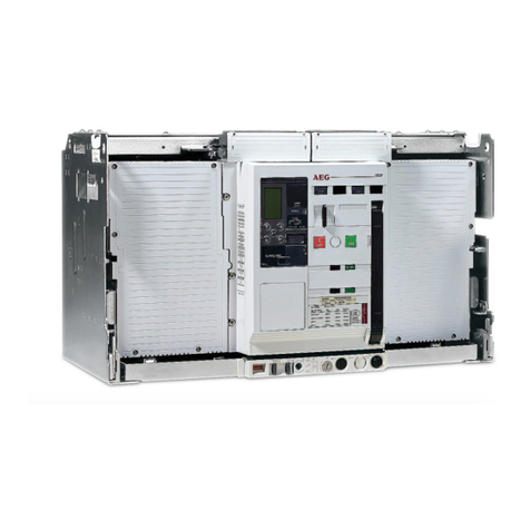
AEG ME10 User manual

perfekt in form und funktion
Power Circuit Breaker
ME10
ed.15-01 CIRCUIT BREAKER
LEISTUNGSSCHALTER
INTERRUTTORE APERTO
MANUAL
HANDBUCH
MANUALE
GB DE IT

WARNUNG
Während des Betriebes ist das in
diesem Handbuch beschriebene Gerät
an hohe, potenziell gefährliche
Spannungen angeschlossen.
Aus Leistungsschaltern können zudem
beim Ausschalten hoher Ströme,
besonders bei Kurzschlüssen, heiße und
ionisierte Gase austreten.
Montage, Inbetriebnahme, Wartung,
Änderung und Nachrüstung dieser
Geräte dürfen deshalb nur von
qualifiziertem Fachpersonal unter
Befolgung der einschlägigen
Sicherheitsvorschriften ausgeführt
werden.
Leistungsschalter müssen während
ihres Betriebes mit dazugehörigen
Abdeckungen versehen sein und / oder
in Gehäusen oder Schaltschränken
unter Berücksichtigung der
Sicherheitsabstände eingebaut sein.
Die Nichtbeachtung dieser Erfordernisse
kann hohe Sachschäden und / oder
schwere Körperverletzungen zur Folge
haben.
AVVERTENZA
Durante il funzionamento, l'apparecchio
descritto in questo manuale è collegato
a tensioni elevate e potenzialmente
pericolose.
Quando l'interruttore commuta correnti
elevate, soprattutto correnti di corto
circuito, possono essere generati gas
caldi e ionizzati.
Solo il personale qualificato è
autorizzato ad installare, mettere in
servizio, mantenere o modificare il
dispositivo, in conformità alle norme di
sicurezza.
L'Interruttore deve essere equipaggiato
con coperture adeguate e/o essere
installato in quadri adatti, tenendo
conto delle distanze di sicurezza
necessarie.
Il mancato rispetto di tali requisiti può
causare danni a cose e/o lesioni gravi
alle persone.
Caution! Important Requirements! Achtung! Wichtige Forderungen! Attenzione! Requisiti importanti!
WARNING
During operation the device described
in this manual is connected to high and
potentially dangerous voltages.
When the circuit breaker is switching
high currents, especially short-circuit
currents, hot and ionized gas may be
emitted.
Only qualified personnel are allowed to
install, commission, maintain or modify
this device in accordance with relevant
safety requirements.
The Circuit Breaker must be equipped
with the appropriate covers and/or be
installed in a suitable enclosure or panel
taking the required safety clearances
into account.
Non Compliance with these
requirements could result in damage to
property and/or severe injury to
personnel.
Lesen Sie bitte diese Betriebsanweisung
und bewahren Sie sie bitte griffbereit auf.
Read this manual and please retain for
future use.
Leggere il presente manuale e conservarlo
per usi futuri.
WARNING
HINTSCONTENT
LOCKS
BREAKER ME10 INTRO BREAKER ACCESSORIES TESTS APPENDIX
TRIP UNIT

1.0 ALLGEMEINE INFORMATION
Installations-, Betriebs- und Wartungs-
Handbuch
ME10 Leistungsschalter
GEFÄHRDUNGSKATEGORIEN
Die folgenden wichtigen, hervorgehoben
Informationen in diesem Dokument warnen vor
möglichen Gefahren oder machen auf
besondere Verfahrenweisen aufmerksam.
Lesen Sie alle Anweisungen aufmerksam durch
und machen Sie sich mit dem Gerät vertraut,
bevor Sie versuchen es zu installieren, zu
betreiben oder Service- und Wartungsarbeiten
an dieser Ausrüstung vorzunehmen.
1.0 GENERAL INFORMATION
Installation, Operation and Maintenance Manual
ME10 Power Circuit Breaker
HAZARD CATEGORIES
The following important highlighted information
appears throughout this document to warn of
potential hazards or to call attention to
information that clarifies a procedure.
Carefully read all instructions and become
familiar with the devices before trying to install,
operate, service or maintain this equipment.
CAUTION: Failure to comply with these
instructions may result in product damage.
NOTICE: An aid meant to assist the user in
performing the set task. Please retain for future
use.
TRADEMARKS
ME10
ME10 TU
WARRANTY
This document is based on information available
at the time of its publication.
While efforts have been made to ensure
accuracy, the information contained herein does
not cover all details or variations in hardware
and software, nor does it provide for every
possible contingency in connection with
installation, operation, and maintenance.
Features may be described herein that are not
present in all hardware and software systems.
AEG assumes no obligation of notice to holders
of this document with respect to changes
subsequently made.
AEG makes no representation or warranty,
expressed, implied, or statutory, with respect to,
and assumes no responsibility for the accuracy,
completeness, sufficiency, or usefulness of the
information contained herein.
No warrantees of merchantability or fitness for
purpose shall apply.
Contact your local sales office if further
information is required concerning any aspect of
ME10 Circuit breaker operation or maintenance.
VORSICHT: Die Nichteinhaltung dieser
Anweisungen kann zu Schäden am Produkt
führen.
HINWEIS: Zeigt wichtige Informationen zur
Hilfe und Klarstellung der Angaben.
SCHUTZMARKEN
ME10
ME10 TU
GARANTIE
Dieses Dokument basiert auf zum Zeitpunkt der
Veröffentlichung verfügbaren Informationen.
Es wurden alle Anstrengungen zur
Vollständigkeit des Handbuchs unternommen,
trotzdem kann die hierin enthaltene Information
sich nicht auf alle Details oder Variationen in
Hard- und Software oder auf alle im
Zusammenhang mit Installation, Betrieb und
Wartung auftretenden Möglichkeiten beziehen.
Außerdem können hier Funktionen beschrieben
sein, die nicht in dem vorliegenden Hard- oder
Software-System vorhanden sind.
AEG übernimmt keine Verpflichtung zur
Mitteilung an die Inhaber dieses Dokuments in
Bezug auf Veränderungen.
AEG macht keine Zusicherungen oder Garantien
und übernimmt keine Verantwortung für die
Richtigkeit, Vollständigkeit oder Nützlichkeit der
hierin enthaltenen Informationen.
Es gibt keine Gewährleistungen der
Marktgängigkeit oder Eignung für einen
bestimmten Zweck.
Wenden Sie sich bitte an Ihr Verkaufsbüro vor
Ort, falls Sie weitere Informationen zu Aspekten
des ME10-Leistungsschalter in Betrieb oder
Wartung benötigen.
ATTENZIONE: Il mancato rispetto di queste
istruzioni può causare danni al prodotto.
AVVISO: Ausilio destinato ad assistere l'utente
nello svolgimento dei propri compiti. Si prega di
conservare per uso futuro.
MARCHI
ME10
ME10 TU
GARANZIA
Questo documento si basa sulle informazioni
disponibili al momento della pubblicazione.
Pur essendo stati intrapresi tutti gli sforzi
possibili per garantirne l'accuratezza, le
informazioni contenute nel presente documento
non coprono tutti i possibili dettagli o le
variazioni a livello hardware e software, né
coprono tutte le possibili casistiche relative a
installazione, funzionamento e manutenzione.
Nel presente documento possono essere
descritte caratteristiche non presenti in tutti i
sistemi hardware e software.
AEG non si assume alcun obbligo di comunicare
ai possessori di questo documento le modifiche
apportate successivamente.
AEG non rilascia alcuna dichiarazione o garanzia
- espressa, implicita o legale - circa le
informazioni contenute nel presente documento,
né si assume alcuna responsabilità sulla loro
accuratezza, la loro completezza, la loro
esaustività o la loro utilità.
Non si applica alcuna garanzia di
commerciabilità o di pertinenza d'uso.
Per ulteriori informazioni riguardanti qualsiasi
aspetto del funzionamento o della
manutenzione dell'interruttore ME10, contattare
l'ufficio vendite locale.
DANGER | GEFAHR | PERICOLO
Indicates a hazardous situation which, if not
avoided, could result in death or serious injury.
Zeigt an, dass eine vermeidbare, gefährliche
Situation entstehen kann, die zum Tod oder zu
schweren Verletzungen führen kann.
Indica una situazione pericolosa che, se non
evitata, può causare morte o lesioni serie.
1.0 INFORMAZIONI GENERALI
Manuale di installazione, uso e manutenzione
Interruttore aperto ME10
CATEGORIE DI RISCHIO
Le importanti informazioni descritte di seguito in
questo documento e opportunamente
evidenziate, intendono segnalare rischi o
richiamare l'attenzione su dettagli che
chiariscono una procedura. Leggere
attentamente tutte le istruzioni e familiarizzare
con i dispositivi prima di cercare di installare, far
funzionare o effettuare manutenzioni sugli
apparecchi.
BREAKER ME10
INTRO
HINTS
1.0
1.0-01

LOCKS
BREAKER ME10 INTRO BREAKER ACCESSORIES TESTS APPENDIX
TRIP UNIT
INHALTSVERZEICHNIS
1.0 - ALLGEMEINE INFORMATIONEN
--------------------------------------------------------
1.1.0 Einführung
Qualitätssicherung
Checkliste Geräteoptionen
Produktserien- & Katalognummer
Maßeinheiten
1.1.1 Kurzbeschreibung
1.1.2 Eigenschaften und Merkmale
1.1.3 Lagerung
1.1.4 Leistungsschild Beschreibung
1.1.5 Werkzeuge, benötigt für die Montage
--------------------------------------------------------
1.2 - PRODUKTSPEZIFIKATIONEN
- Tabellen
--------------------------------------------------------
1.3 - INSTALLATION
1.3.1 Heben- und Montage
Verwendung des Hebeadapters
1.3.2 Leistungsschalter für Festeinbau
Montage
1.3.3 Leistungsschalter für Ausfahrtechnik
Montage
Ausbau aus dem Einschubträger
Einbau in den Einschubträger
1.3.4 Standard Busverbindungen
von Fest- und/oder Einschubtechnik
1.3.5 Hilfstrennblöcke
Lagebeschreibung
Verwendung
Tabelle -- Anschlussschema
Tabelle -- Geräteanschlüsse Block A - C
--------------------------------------------------------
1.4 - BETRIEB
1.4.1 Energiespeicherung in der
Schaltermechanik
Manuell
Elektrisch
1.4.2 Betriebsstellungen Schalter
1.4.3 Leistungsschalter Einschaltung
1.4.4 Leistungsschalter Ausschaltung
1.4.5 Leistungsschalter Entnahme
1.4.6 Leistungsschalter Einbau/Einschub
1.4.7 Betriebsstellungen des Einschubträgers
--------------------------------------------------------
2.0 - AUSLÖSEEINHEIT
Allgemeine Information
2.1 Produktbeschreibung
2.2 Betrieb
2.3 LCD Display-Betriebseinstellungen
2.5 Auslösekurven
2.6 ...
2.7 Montagehinweise
2.8 Anschlussschema
2.9 Fehlersuche
2.10 Katalognummern Code Auslöser
--------------------------------------------------------
CONTENT
1.0 - GENERAL INFORMATION
--------------------------------------------------------
1.1.0 Introduction
Quality Assurance
Options Check Sheet
Product Serial & Catalogue Number
Measurement Units
1.1.1 Short Product Description
1.1.2 Features and Characteristics
1.1.3 Storage
1.1.4 Rating label description
1.1.5 Tools Needed for Installation
--------------------------------------------------------
1.2 - PRODUCT SPECIFICATIONS
- Tables
--------------------------------------------------------
1.3 - INSTALLATION
1.3.1 Lifting and Mounting
Using Lifting Beams
1.3.2 Fixed-Pattern Circuit Breaker
Installation
1.3.3 Drawout Pattern Circuit Breaker
Installation
Removal from Cassette
Mounting in Cassette
1.3.4 Standard Bus connection
of Fixed AND/OR Drawout pattern.
1.3.5 Secondary Disconnect Terminal Blocks
Location
Use
Table -- General schematics
Table -- Definition of connected devices
to Block A - C
--------------------------------------------------------
1.4 - OPERATION
1.4.1 Charging of Main Springs
Manually
Electrically
1.4.2 Sequence of breaker operation
1.4.3 Circuit breaker closing operation
1.4.4 Circuit breaker opening operation
1.4.5 Circuit breaker Withdrawal
1.4.6 Circuit breaker Insertion/Cassette
1.4.7 Sequence of operation cassette
--------------------------------------------------------
2.0 - TRIP UNIT
General Information
2.1 Product description
2.2 Operation
2.3 LCD Screen /Operating Modes
2.5 Time current curves
2.6 ...
2.7 Installation
2.8 Connection scheme
2.9 Troubleshooting
2.10 Catalogue code build
--------------------------------------------------------
CONTENUTO
1.0 - INFORMAZIONI GENERALI
--------------------------------------------------------
1.1.0 Introduzione
Garanzia di qualità
Scheda verifica opzioni
Descrizione codice catalogo
Numero di serie del prodotto & del catalogo
1.1.1 Breve descrizione del prodotto
1.1.2 Funzioni e caratteristiche
1.1.3 Stoccaggio
1.1.4 Descrizione dati di targa
1.1.5 Attrezzature necessarie per
l'installazione
--------------------------------------------------------
1.2 - SPECIFICHE DI PRODOTTO
- Tabelle
--------------------------------------------------------
1.3 - INSTALLAZIONE
1.3.1 Sollevamento e montaggio
Uso dei bracci di sollevamento
1.3.2 Interruttore in esecuzione fissa
Installazione
1.3.3 Interruttore in esecuzione estraibile
Installazione
Rimozione dalla parte fissa
Montaggio nella parte fissa
1.3.4 Connessioni standard
Versioni in esecuzione fissa e/o estraibile.
1.3.5 Morsettiere dei circuiti ausiliari
Posizione
Uso
Tabella -- Schemi generali
Tabella -- Definizione dei dispositivi
collegati a Morsettiera A - C
--------------------------------------------------------
1.4 - FUNZIONAMENTO
1.4.1 Carica delle molle principali
Manuale
Elettrica
1.4.2 Sequenza di funzionamento
dell'interruttore
1.4.3 Chiusura dell'interruttore
1.4.4 Apertura dell'interruttore
1.4.5 Estrazione dell'interruttore
1.4.6 Inserimento dell'interruttore/parte fissa
1.4.7 Sequenza di manovra della parte fissa
--------------------------------------------------------
2.0 - RELÈ DI PROTEZIONE
Informazioni generali
2.1 Descrizione del prodotto
2.2 Funzionamento
2.3 Modalità schermo LCD
2.5 Curve di intervento
2.6 ...
2.7 Installazione
2.8 Schema di connessione
2.9 Risoluzione dei problemi
2.10 Struttura codici catalogo
--------------------------------------------------------
1.0-02

BREAKER ME10
INTRO
CONTENT
1
3.0 - CHIUSURE E INTERBLOCCHI
3.1 Pannello anteriore interruttore
- Lucchettaggio di sicurezza interruttore
- Chiusura di sicurezza interruttore
- Lucchettaggio pulsante
3.2 Parte fissa interruttore in esecuzione
estraibile
- Lucchettaggio serrande
- Lucchettaggio accesso maniglia di manovra
- Lucchettaggio guide di supporto
- Chiusura di sicurezza parte fissa
- Interblocco interruttore in esecuzione
estraibile
- Sistema di prevenzione inserimento errato
(interblocco)
- Interblocco porta
3.2.1 Apertura forzata serrande
3.2.2 Blocco serranda isolamento
3.3 Interblocco di più interruttori
- interblocco 1 di 2 & 3
- interblocco 2 di 3 & 3 con priorità
3.4 Interblocco di rete
3.5 Tabelle opzioni di blocco
--------------------------------------------------------
4.0 - DESCRIZIONE ACCESSORI
Informazioni generali
4.1 Sganciatori/bobine
4.2 Motore di ricarica molle
4.3 Contatti
4.4 Accessori d'installazione
4.5 Altri accessori
4.6 Parti di ricambio
--------------------------------------------------------
5.0 - MANUTENZIONE, VERIFICA E
RISOLUZIONE DEI PROBLEMI
5.1 Manutenzione
- Programma di ispezione
5.2 Procedura di pulizia
- Ispezione contatti d'arco
- Ispezione meccanismi principali interruttore
5.3 Controllo parte fissa
5.4 Controllo usura contatto
5.5 Controllo contatti di sezionamento
(versione in esecuzione estraibile)
5.6 Controllo morsetti di alimentazione e
sbarre
5.7 Lubrificazione
5.8 Verifica
- Verifica Relè di Protezione
5.9 Risoluzione dei problemi
--------------------------------------------------------
6.0 - APPENDICE
6.1 Descrizione codice catalogo
6.2 Dimensioni
6.3 Post-vendita
3.0 - LOCKS AND INTERLOCKS
3.1 Breaker front Fascia
- Breaker Security Padlocking
- Breaker Security Keylocking
- Pushbutton Padlocking
3.2 Drawout Breaker Cassette
- Shutter Security Padlocking
- Racking handle access Padlocking
- Support Slides Padlocking
- Cassette Security Keylocking
- Standard Drawout Breaker Interlock
- Mis insertion device (Interlock)
- Door interlock
3.2.1 Shutter force open feature
3.2.2 Isolation Shutter Locking
3.3 Interlocking of Multiple Breakers
- 1 of 2 breaker interlock
- 1 of 3 breaker interlock
- 2 of 3 breaker interlock
- 2 of 3 breaker interlock with priority
3.4 Network Interlock
3.5 Tables Locking options
--------------------------------------------------------
4.0 - ACCESSORIES DESCRIPTION
General Information
4.1 Releases / Coils
4.2 Electrical Charging Motor
4.3 Contacts
4.4 Installation parts
4.5 Other Accessories
4.6 Spare parts
--------------------------------------------------------
5.0 - MAINTENANCE, TESTING AND
TROUBLESHOOTING
5.1 Maintenance
- Inspection Schedule
5.2 Cleaning Procedure
- Arcing Contacts Inspection
- Circuit Breaker Main Mechanism
Inspection
5.3 Cassette Inspection
5.4 Contact wear Inspection
5.5 Isolating Contacts (Drawout Type)
Inspection
5.6 Power Terminals and Busbar Inspection
5.7 Lubrication
5.8 Testing
- Trip Unit Testing
5.9 Troubleshooting
--------------------------------------------------------
6.0 - APPENDIX
6.1 Catalogue number description
6.2 Dimension
6.3 Service
3.0 - SCHLÖSSER UND VERRIEGELUNGEN
3.1 Leistungsschalter Frontplatte
- Verriegelung mit Vorhängeschlössern
- Leistungsschalter Schlüsselsperren
- Drucktaster-Sperrung
3.2 Ausfahrtechnik Einschubträger
- Sicherheitsblenden Verriegelung
- Einfahrkurbel Einsteckloch-Verriegelung
- Schienensperrung mit Vorhängeschloss
- Einschubträger Schlüsselsperren
- Standard Einschub-Schalterverriegelung
- Verwechslungsschutz
- Türverriegelung
3.2.1 Schutzblenden Öffnungsvorrichtung
3.2.2 Schutzblenden Verriegelung
3.3 Schalter zu Schalter Verriegelung
- 1 von 2 Leistungsschalter-Verriegelung
- 1 von 3 Leistungsschalter-Verriegelung
- 2 von 3 Leistungsschalter-Verriegelung
- 2 von 3 Schalter-Verriegelung mit Vorrang
3.4 Network Interlock
3.5 Tabelle Verriegelungsarten
--------------------------------------------------------
4.0 - ZUBEHÖRBESCHREIBUNG
Allgemeine Informationen
4.1 Module / Betrieb
4.2 Motorantrieb
4.3 Kontakte / Schalter
4.4 Montagezubehör
4.5 Weiteres Zubehör
4.6 Ersatzteile
--------------------------------------------------------
5.0 - WARTUNG, PRÜFUNG UND FEHLERSUCHE
5.1 Wartung
- Inspektions-Ablaufplan
5.2 Reinigungsvorgänge
- Lichtbogenkontakte Inspektion
- Leistungsschaltermechanik-
Hauptinspektion
5.3 Einschubträger-Inspektion
5.4 Kontaktverschleiß-Inspektion
5.5 Trennkontakte (Einschub) Inspektion
5.6 Hauptanschlüsse und Sammelschienen-
Inspektion
5.7 Schmierung
5.8 Tests
- Auslöseeinheiten-Test
5.9 Fehlersuche
--------------------------------------------------------
6.0 - ANHANG
6.1 Katalognummer Beschreibung
6.2 Abmessungen
6.3 Service
1.0-03

LOCKS
BREAKER ME10 INTRO BREAKER ACCESSORIES TESTS APPENDIX
TRIP UNIT
Inhaltsverzeichnis:
1.1.0 Einführung
Qualitätssicherung
Checkliste Geräteoptionen
Produkt-Seriennummer
Maßeinheiten
1.1.1 Kurzbeschreibung
1.1.2 Eigenschaften und Merkmale
1.1.3 Lagerung
1.1.4 Leistungsschild Beschreibung
1.1.5 Werkzeuge, benötigt für die Installation
Content:
1.1.0 Introduction
Quality Assurance
Options Check Sheet
Product Serial Number
Measurement Units
1.1.1 Short Product Description
1.1.2 Features and Characteristics
1.1.3 Storage
1.1.4 Rating label description
1.1.5 Tools Needed for Installation
Contenuto:
1.1.0 Introduzione
Garanzia di qualità
Scheda verifica opzioni
Numero di serie del prodotto
Unità di misura
1.1.1 Breve descrizione del prodotto
1.1.2 Funzioni e caratteristiche
1.1.3 Stoccaggio
1.1.4 Descrizione dati di targa
1.1.5 Attrezzature necessarie per
l'installazione
1.1-00
Fig. 1.0: ME10 Front View
A) Accessory Indicator
B) Charging Handle
C) Electrical ON (Close)
D) Manual ON (Close)
E) Closing Spring Discharge Button
F) ON/OFF Pushbutton Status
G) ON/OFF Status Indicator
H) Spring Charge Status
I) Breaker Rating
J) Ronis/Profalux Key
K) Castell Key
L) Operations Counter
M) Ready to Close Indicator
N) Manual OFF (Open)
O) Breaker Padlock
P) Trip Unit
Q) Manual reset for optional Network Interlock coil
Fig. 1.0: ME10 : vista frontale
A) Indicatore accessori
B) Leva di carica manuale
C) ON Elettrico (Chiuso)
D) ON Manuale (Chiuso)
E) Pulsante di scarico molla di chiusura
F) Stato Pulsante ON/OFF
G) Indicatore di stato ON/OFF
H) Stato carico molla
I) Dati nominali interruttore
J) Chiave Ronis/ Profalux
K) Chiave Castell
L) Contatore di manovre
M) Indicatore "pronto a chiudere"
N) OFF Manuale (aperto)
O) Anello per lucchetto
P) Relè di Protezione
Q) Ripristino manuale per bobina d'interblocco
di rete opzionale
Abb. 1.0: ME10 Vorderansicht
A) Anzeige der Auslöse-Module
B) Spannhebel
C) Elektrische EIN (Schließen)
D) Manuell EIN (Schließen)
E) Antriebsfeder Entspannungstaster
F) EIN / AUS Drucktaster Statusanzeige
G) EIN / AUS-Statusanzeige
H) Anzeige Federspannungs-Status
I) Leistungsschild
J) Ronis / Profalux Schlösser
K) Castell Schloss
L) Schaltungszählwerk
M) Einschaltbereit-Anzeige
N) Manuell AUS (Öffnen)
O) Schalter Vorhängeschloss
P) Auslöseeinheit
Q) Manueller Resetknopf für optionale Network-
Interlock Einheit
A
B
E
G
C
F
D
H
I
J
K
L
M
N
O
P
Q
Global Catalogue Number
Katalognummer
Codice globale di catalogo
Serial Number
Seriennummer
Numero di serie
J
L
M
N
P
A
B
G
D
H
I
Envelope T
| Baugröße T
| Taglia T

BREAKER ME10
BREAKER
INTRO
1.1
1.1 INTRODUZIONE
Garanzia di qualità
Tutte gli interruttori ME10 sono stati progettati e
realizzati secondo i più elevati standard tecnici.
AEG utilizza procedure rigorose che garantiscono il
rispetto delle norme tecniche, mantenendo
contemporaneamente i massimi livelli di qualità dei
prodotti.
Scheda verifica opzioni
Ogni interruttore è corredato da una scheda di
controllo che elenca tutti i dati nominali e gli
accessori opzionali inclusi nell'interruttore, nella
parte fissa e nel Relè di Protezione (se ordinati)
Descrizione codice di catalogo
vedere Appendice
Numero di serie del prodotto & codice di catalogo
Quando si comunica con AEG in merito a qualsiasi
aspetto relativo a questo dispositivo, si prega di
citare il numero di serie e il codice globale di
catalogo. Il numero di serie è univoco per ogni
dispositivo; il codice di catalogo fornisce tutti i dati
tecnici e di configurazione.
-- Sul lato superiore di una staffe di montaggio.
-- Sul lato sinistro (visto dal davanti) della parte
frontale.
1.1.1 Breve descrizione del prodotto
L'interruttore aperto ME10 è un interruttore
automatico progettato per soddisfare le norme
ANSI, UL e IEC. Questo manuale è dedicato in modo
specifico ai progetti conformi alla norma IEC/EN
60947; per altre norme contattateci.
Il dispositivo è progettato per l'utilizzo in reti con
tensioni fino a 1000 VAC o a 750 VDC e per essere
totalmente selettivo con gli altri interruttori ME10 e
MM/MC di AEG.
Il prodotto è disponibile in versioni a 3 o 4 poli e in
tre taglie e può essere utilizzato per correnti
nominali da 80 fino a 6400 ampere.
Come interruttore, ME10 può essere equipaggiato
con quattro diversi tipi di Relè di Protezione
elettronica - ciascuno dotato della medesima
interfaccia universale e di schermo LCD.
È disponibile anche in versione non automatica
(sezionatore - senza Relè di Protezione). Sia
l'interruttore che il sezionatore sono disponibili in
esecuzione fissa o estraibile.
I dispositivi ME10 offrono una combinazione tra alto
potere di interruzione e tenuta alle correnti di breve
durata e possono essere utilizzati come interruttori
generali o sezionatori di rete.
1.1.2 Funzioni e caratteristiche
Funzioni standard e opzionali
Corrente nominale di breve durata:
Fino a 100 kA per 1 secondo
Potere di interruzione:
Fino a 150 kA a 440 V e 100 kA a 690 V
Corrente nominale
I dispositivi hanno una corrente nominale del 100%
fino a una temperatura ambiente di 50 °C in aria
libera.
1.1-01
1.1 INTRODUCTION
Quality Assurance
All ME10 circuit breakers have been designed and
manufactured to the highest technical standards.
AEG uses strict procedures ensuring that the
mentioned technical standards are met whilst
maintaining a first class product quality.
Options Check Sheet
Each circuit breaker comes with an options check
sheet that lists all optional features and accessories
included in the circuit breaker, cassette and trip unit
(if ordered)
Catalogue number description
see Appendix
Product Serial & Catalogue Number
When communicating with AEG on any aspect of
this device please mention the serial number & the
global catalogue number.
The serial number is unique for each device, whilst
the catalogue number provides all technical and
configuration data.
-- On the top face of one of the retractable lifting
brackets.
-- On the left side (viewed from front) of the front
cover.
1.1.1 Short Product description
The ME10 Power Circuit breaker is an Air Circuit
Breaker designed to meet the Global ANSI, UL and
IEC standards. This manual being specifically
dedicated to the design meeting the IEC/EN
60947 standard, for other standards please
contact us.
The device is designed for use in networks with
voltages up to 1000V AC or 750V DC and to be fully
selective with other ME10 and AEG MM/MC Circuit
Breakers.
It is available as 3 or 4 pole device in three
envelopes and can be used for current ratings from
80 up to 6400 Amps.
As a breaker the ME10 can be equipped with one of
four Electronic Trip Unit types each having the same
universal setting interface and an LCD screen.
A Non Automatic (Switch Disconnector) version
(without trip unit) is also possible. Both Breaker and
Switch Disconnector types are available in a Fixed
or Drawout pattern.
ME10 devices offer a combination of high
interruption and short time current withstand
ratings and can be used in applications as Mains,
Coupler/Tie or feeder breaker or switch
disconnector.
1.1.2 Features and Characteristics
Standard and Optional Features
Rated Short Time Withstand Current::
Up to 100kA for 1 sec
Short Circuit / Interruption Rating:
(Breaking Capacity)
Up to 150kA at 440V & 100kA at 690V
Rated Current:
The devices have a 100% normal current rating up
to an ambient temperature of 50°C in free air.
1.1 EINFÜHRUNG
Qualitätssicherung
Alle ME10 Leistungsschalter wurden entworfen und
hergestellt, um die höchsten technischen Standards
zu verwirklichen.
Strenge Verfahren zur Einhaltung der technischen
Vorschriften stellen eine erstklassige
Produktqualität sicher.
Checkliste Geräteoptionen
Jeder Leistungsschalter wird mit einer Checkliste
ausgeliefert, die alle optionalen Funktionen des
Leistungsschalters, des Einschubträgers und der
Auslöseeinheit (wenn bestellt) auflistet.
Katalognummern Beschreibung
siehe Anhang
Produktserien- und Katalognummer
Bitte halten Sie die Serien- und Katalognummer
verfügbar, wenn Sie über diesen Schalter mit
unserem Service sprechen. Jeder Schalter hat eine
einmalige Seriennummer und eine Katalognummer,
welche die technischen Daten und die
Schalterkonfiguration wiedergibt.
-- Auf der Oberseite eines der einziehbare
Hebebügel.
-- An der linken Seite (von vorn gesehen) der
Frontabdeckung.
1.1.1 Kurzbeschreibung
Der ME10 Leistungschalter ist ein Schalter der für
die weltweiten Vorschriften wie ANSI, UL und IEC-
Normen entwickelt wurde. Dieses Handbuch ist
speziell auf die Ausführungsvariante der IEC / EN
60947 Vorschriften ausgelegt. Für weitere
Vorschriften wenden Sie sich bitte an uns.
Das Gerät ist für den Einsatz in Netzen mit
Spannungen bis zu AC 1000V oder DC 750V
entwickelt und in vollem Umfang selektiv mit
anderen ME10- und AEG MM/MC-
Leistungsschaltern.
Die Leistungsschalter sind als 3- oder 4-polige
Geräte in drei Baugrößen verfügbar und können für
Nennströme von 80 bis 6400 Ampere verwendet
werden.
Als Leistungsschalter kann der ME10 mit einem von
vier möglichen elektronischen Auslösertypen
bestückt werden, jeweils mit den gleichen
universellen Einstellmöglichkeiten und einem LCD-
Display.
Eine Trennschalter-Version (Schalter ohne
Auslöseeinheit) ist ebenfalls lieferbar. Beide,
Leistungsschalter und Lasttrennschalter, sind in den
Grundvarianten Festeinbau oder Ausfahrtechnik
verfügbar.
ME10-Geräte bieten eine Kombination aus hohem
Ausschaltvermögen und
Bemessungskurzzeitstromfestigkeit und können für
Anwendungen in Leitungsnetzen, als Koppel-
/Verbindungsschalter, Einspeiseschalter oder
Lasttrennschalter eingesetzt werden.
1.1.2 Eigenschaften und Merkmale
Standard und optionale Funktionen
Bemessungskurzzeitstromfestigkeit::
Bis zu 100kA für 1 Sek.
Kurzschluss / Unterbrechungswerte:
(Ausschaltvermögen)
bis 150kA bei 440V und 100kA bei 690V
Strombelastbarkeit:
Die Schalter sind in freier Luft bei bis zu 50ºC
Umgebungstemperatur mit 100% Auslastung
einsetzbar.

LOCKS
BREAKER ME10 INTRO BREAKER ACCESSORIES TESTS APPENDIX
TRIP UNIT
INTRO
SPECIFICATIONINSTALLATIONOPERATIONTRIP UNIT
Connessione alimentazione
I dispositivi ME10 possono essere alimentati dai
morsetti superiori o inferiori.
Meccanismo accumulo energia
L'interruttore ME10 utilizza un meccanismo di
accumulo di energia che può essere caricato
manualmente o elettricamente. Per la ricarica
manuale viene utilizzata la leva di carica manuale;
può essere aggiunto un motore di carica per le
molle, dotato di un contatto di indicazione. Il tempo
di chiusura del dispositivo è inferiore a cinque mezzi
cicli.
La chiusura e l'apertura possono essere avviate in
remoto o attraverso i pulsanti frontali. Un ciclo O-C-
O è possibile senza ricarica. Il meccanismo di
funzionamento dell'interruttore è a sgancio libero
ed è dotato di un sistema di antichiusura integrato.
Accessori & Relè di Protezione
montati in fabbrica o installabili sul campo:
Gli accessori comuni agli interruttori di tutte le taglie
sono disponibili in due differenti versioni.
-- 1. montati in fabbrica
-- 2. installabili sul campo, forniti con tutti
i necessari collegamenti e accessori di fissaggio.
Bobine / Sganciatori
ME10 taglie 1, 2 e 3 ha quattro alloggiamenti dove
inserire le bobine.
Da sinistra a destra: il primo accetta una bobina a
lancio di corrente (ST1 o SST1) o una bobina di reset
(RRC). Il secondo una bobina di minima tensione
(UVR1). Il terzo una bobina di chiusura (CC) o una
bobina di chiusura a comando (CCC). Il quarto
ospita una seconda bobina a lancio di corrente o di
minima tensione (ST2, SST2, o UVR2).
ME10 taglia T ha tre alloggiamenti dove inserire le
bobine.
Da sinistra a destra: il primo accetta una bobina a
lancio di corrente (ST o SST). Il secondo una bobina
di chiusura (CC) o una bobina di chiusura a
comando (CCC), Il terzo una bobina di minima
tensione (UVR).
La bobina a lancio di corrente è disponibile in
versione continuamente alimentata (ST) o
alimentata impulsivamente (SST); la bobina di reset
(RRC) solo come continuamente alimentata.
Le bobine di minima hanno un ritardo fino a 50ms
(*) mentre un modulo esterno di ritardo (TDM) è
avere disponibile per ritardi maggiori.
Entrembe le bobine di chiusura sono dotate di un
sistema di antichiusura integrato.
Sulle taglie 1, 2 e 3 un indicatore di stato opzionale
è disponibile per le bobine RRC, ST, CC e UVR. Questi
possono essere riportati all'esterno attraverso le
opzioni di comunicazione del Relè di Protezione e/o
attraverso la morsettiera dei circuiti ausiliari.
(*) Alcune varianti senza ritardo sono disponibili su
richiesta.
Interblocco di rete
ME10 solo per Taglia 1, 2 e 3
Sostituendo una bobina di sgancio a lancio di
corrente (ST) e una bobina di minima tensione (UVR),
questo dispositivo opzionale blocca l'interruttore
elettricamente e meccanicamente.
Stato contatto rete/interruttore:
L'indicazione OPEN/CLOSED, ON/OFF è riportata
sulla copertura anteriore.
Motore di ricarica molle:
Gruppo motore/trasmissione, facilmente
accessibile.
Pulsante di chiusura elettrica:
Situato sulla copertura anteriore; chiude
elettricamente l'interruttore.
1.1-02
Connection of Power supply
ME10 devices can be fed from top or bottom
terminals.
Stored Energy Mechanism:
An ME10 Circuit Breaker uses a stored energy
mechanism that can be charged manually or
electrically. For manual charging the operating
handle is used ,a spring charging motor supplied
with an indication contact can be added for
electrical charging. Device closing time is less than
five half cycles.
Closing and opening can be initiated remotely or via
the front cover push buttons. An O-C-O cycle is
possible without recharging. The breaker operating
mechanism is trip-free and has an integrated anti-
pumping system.
Factory fitted -OR-
Field installable Accessories & Trip Units.
Accessories common to all breaker envelopes are
available in two different versions.
-- 1. Factory Mounted units
-- 2. Field installable Units supplies with all
necessary connection & Fixation hardware.
Coils/Releases
The ME10 Envelopes 1, 2 & 3 has four unique
locations in which coils/releases can be clicked:
From left to Right: The first accepts a Shunt
Release (ST1 or SST1) or a Remote Reset coil (RRC).
The second takes an Undervoltage release (UVR1).
The third a Closing (CC) or Command Closing coil
(CCC). The fourth allows the placing of a second
Shunt or Undervoltage release (ST2, SST2 or UVR2).
The ME10 Envelope T has three unique locations in
which coils/releases can be clicked:
From left to Right: The first accepts a Shunt
Release (ST or SST).
The second takes a Closing (CC) or Command
Closing coil (CCC). The thirds allows for a
Undervoltage release (UVR).
The shunt release is available as a continuously
rated (ST) or impulse rated type (SST), the Remote
Reset Coil is only available as a continuously rated
type.
Undervoltage releases have a built in time delay of
up to 50ms *) whilst an external time delay module
is available if longer time delays are required (TDM).
Both closing coils are equipped with an anti-
pumping mechanism.
On the Envelopes 1, 2 & 3 optional status indication
contacts are available on the RRC, ST, CC and UVR-
coils. They can be wired out through the trip unit
communication option and/or through the
secondary disconnect terminals.
(*) On request some variants are available without
delay.
Network Interlock:
ME10 envelopes 1, 2 & 3 only
Replacing one Shunt release (ST) and one
Undervoltage release (UVR) this optional device
locks out the breaker electrically and mechanically.
Breaker / Main Contact Status:
OPEN/CLOSED, ON/OFF indication is provided on the
front cover.
Motor Operator:
Motor/gearbox unit; easily accessible.
Electrical Closing Button:
Located on the front cover; electrically closes
breaker.
Umkehr-Einspeisung
Leistungsschalter ME10 können von oberen oder
von unteren Anschlüssen eingespeist werden.
Federkraftspeicher:
ME10 Schalter werden mit gespeicherten
Energiemechanismen betrieben. Sie können
manuell mit Spannhebel oder elektrisch von einem
Antriebsmotor gespannt werden. Die Einschaltzeit
beträgt weniger als 50 ms. Schließ- und Öffnungs-
Betätigungen können Fernbetätigt oder über die
Drucktasten in der vorderen Abdeckung eingeleitet
werden. Ein Öffnen-Schließen-Öffnen Zyklus ist
ohne Wiederaufladung möglich. Die
Schaltermechanik ist eine Freiauslösungs-Mechanik
und ist mit einem integrierten Anti-Pumpsystem
ausgestattet.
Werkseinbau - oder -
Vorort installierbare Auslöseeinheit & Zubehör:
Das zu den Baugrößen gehörige Zubehör gibt es in
zwei Varianten:
-- 1. Werkseitiger Zubehöreinbau
-- 2. Vorort installierbares Zubehör, geliefert mit
allen erforderlichen Anbau- und Befestigungsteilen.
Module
Die ME10 Baugrößen 1, 2 & 3 haben vier
gleichartige Steckplätze, in denen Module
positioniert werden können:
Von links nach rechts: Der erste Steckplatz nimmt
einen Arbeitsstromauslösern (ST1 oder SST1) oder
Fern-Reset Steller (RRC) auf. Der zweite nimmt einen
Unterspannungsauslöser (UVR1), der dritte einen
Abrufmagneten (CC) oder Befehls-Abrufmagnet
(CCC) auf. Der vierte Steckplatz ermöglicht die
Platzierung eines zweiten Arbeitsstrom- oder
Unterspannungsauslöser (ST2, SST2 oder UVR2).
Die ME10 Baugröße T hat drei gleichartige
Steckplätze, in denen Module positioniert werden
können.
Von links nach rechts: Der erste Steckplatz nimmt
einen Arbeitsstromauslösern (ST oder SST) auf.
Die zweite nimmt einen Abrufmagneten ( CC ) oder
Befehls-Abrufmagneten (CCC) auf, der dritte
Steckplatz ermöglicht eine Unterspannungsauslöser
(UVR) Plazierung. Der Arbeitsstromauslösern steht
als kontinuierlicher (ST) oder impulsgesteuerter Typ
(SST) zur Verfügung, der Fern-Reset Steller (RRC) ist
nur als kontinuierlich arbeitender Typ verfügbar.
Unterspannungsauslöser haben eine
Zeitverzögerung von bis zu 50 ms *), während ein
externes Zeitverzögerungsmodul (TDM) für größere
Zeitverzögerungen genutzt werden kann. Beide
Abrufmagneten (CC + CCC) sind mit einem
'Antipumpmechanismus' ausgestattet. Für
Baugröße 1, 2 & 3 sind optionale Statusanzeige-
Kontakte für die RRC, ST, CC und UVR-Module
erhältlich. Sie können über die Kommunikations-
Option der Auslöseeinheit und/oder durch die
Hilfstrennblöcke verdrahtet werden.
*) Auf Nachfrage sind unverzögerte Ausführungen
verfügbar.
Network Interlock:
Nur für ME10 der Baugrößen 1, 2 und 3.
Durch den Ersatz von einem Arbeitsstromauslöser
(ST) und einem Unterspannungsauslöser (UVR) kann
dieses optionale Modul den Leistungsschalter
elektrisch und mechanisch sperren.
Leistungsschalter / Hauptkontaktstatus:
Offen / Geschlossen, EIN / AUS-Anzeigen sind in der
vorderen Schalterabdeckung verfügbar.
Motorantrieb:
Motor/Getriebe-Einheit; leicht zugänglich.
Elektrischer Schließ-Drucktaster:
Platziert in der vorderen Abdeckung; schließt den
Schalter elektrisch.

BREAKER ME10
BREAKER
INTRO
1.1
Staffe di montaggio
Per facilitare il montaggio di un ME10 in taglia 1 o 2
in esecuzione fissa sono disponibili degli opportuni
kit. Questi sono raccomandati in caso fosse
utilizzato un interruttore aperto dotato di morsetti di
connessione ad accesso anteriore.
Modalità di connessione
Sono disponibili dei kit di connessione per adattare
la modalità di connessione standard
dell'interruttore ad esecuzione fissa (orizzontale
posteriore) a quella anteriore o verticale posteriore.
Le parti fisse delle esecuzioni estraibili sono fornite
con connettori universali posteriori, orizzontali o
verticali, o con connessioni dedicate orizzontali
posteriori o attacchi frontali.
Contatti ausiliari
Taglia T:
-- contatti di potenza 3NA & 3NC (default)
-- di potenza, 4NA & 4NC
Taglie 1, 2 e 3:
-- contatti di potenza 3NA & 3NC (default)
-- di potenza, 8NA & 8NC
– di potenza, 3NA & 3NC
+ contatti di segnale 2NO & 2NC
– di potenza, 4NA & 4NC
+ di segnale 4NA & 4NC
Interblocchi
Funzione di interblocco standard
Interruttore in esecuzione estraibile
Le parti fisse e la parte mobile del dispositivo sono
equipaggiate con un interblocco che impedisce la
chiusura dell'interruttore a meno che non sia in
posizione TEST o CONNECT.
Quando i contatti principali dell'interruttore sono
chiusi, un secondo interblocco evita l'inserimento
della maniglia di manovra nell'apertura della parte
fissa.
Indicatori di stato dell'interruttore:
Gli indicatori standard includono:
-- indicatore di stato dell'interruttore, che mostra
la condizione dei contatti principali (OPEN, CLOSED).
-- stato delle molle di chiusura, che indica "molla
carica" o scarica (CHARGED o DISCHARGED)
-- indicatore di "pronto a chiudere", che fornisce
un'indicazione visibile di disponibilità per la
chiusura.
-- indicatore di posizione, che indica se
l'interruttore è in posizione inserito-test-estratto
(CONNECT, TEST o DISCONNECT).
-- L'interruttore include anche un contatto che
fornisce l'indicazione dello stato del contatto
principale.
Sistema di prevenzione inserimento errato
Un sistema opzionale di prevenzione inserimento
errato impedisce l'errato accoppiamento tra
interruttore e parte fissa.
Questo evita:
a) l'inserimento di un interruttore con caratteristiche
nominali inferiori in una parte fissa con
caratteristiche nominali superiori
b) l'inserimento di una interruttore con
caratteristiche nominali superiori in una parte fissa
con caratteristiche nominali inferiori.
Porta passante:
Il meccanismo di manovra dell'interruttore è
accessibile attraverso la porta anteriore e permette
di scollegare/ estrarre l'interruttore in modo sicuro
senza aprire la porta, evitando di esporre il
personale a parti sotto tensione durante il processo.
Dispositivi di blocco con lucchetto
ME10: Taglie 1,2 e 3
Gi interruttori aperti sono equipaggiati con diversi
dispositivi lucchettabili sia in esecuzione fissa che
estraibile. E' possibile, tramite un lucchetto di 5-
8mm, permettere il blocco in posizione di OFF
dell'interruttore.
1.1-03
Mounting Brackets
Kits are available to facilitate wall mounting of an
ME10 Envelope 1 or 2 Fixed pattern device. These
are recommended for use when a Power Circuit
breaker is equipped with Front access Connection
terminals.
Connection modes
Connection sets are available to adapt the standard
connection mode (Rear Horizontal) of the fixed
pattern breaker to a front or Vertical rear
connection mode.
The cassettes for the devices in drawout mode are
supplies with universal connectors for Rear
horizontal or vertical connection or with dedicated
Rear horizontal or Front Flat connections.
Auxiliary Contacts
Envelope T:
-- Power rated 3NO & 3NC (default)
-- Power rated, 4NO & 4NC
Envelope 1, 2 & 3:
-- Power rated 3NO & 3NC (default)
-- Power rated, 8NO & 8NC
– Power rated, 3NO & 3NC
+ signal rated 2NO & 2NC
– Power rated, 4NO & 4NC
+ signal rated 4NO & 4NC
Interlocks
Standard Interlocking Feature
Drawout Breaker
The cassettes and device mobile part are equipped
with a interlock that prevents the breaker from
closing unless it is in the TEST or CONNECTED
position.
When the main breaker contacts are closed a
second interlock prevents insertion of the devices
racking handle into the aperture on the cassette.
Breaker Status Indicators:
Standard Indicators include:
-- The breaker status indicator shows the
condition of the main contacts (OPEN, CLOSED).
-- The status of the closing springs is indicated as
CHARGED or DISCHARGED.
-- Ready to Close Indicator provides visible
indication/readiness for close operation.
-- The draw-out position indicator displays
whether the breaker is in the CONNECT, TEST or
DISCONNECT position.
-- The breaker also includes a switch that provides
main contact status indication.
Mis insertion Feature
An optional mis insertion feature prevents
mismatching breakers and cassettes /
substructures.
This prevents
a) inserting a breaker with a lower rating into a
higher rated cassette/substructure and
b) inserting a higher rated breaker into a lower
rated cassette/substructure.
Through-door Racking:
The breaker racking mechanism is accessible
through the front door and permits safely
disconnecting/withdrawing the circuit breaker
without opening the door and exposing personnel
to live parts during the process.
Padlocking devices:
ME10: Envelopes 1, 2 & 3
Power Circuit Breakers are equipped with several
padlocking devices in fixed and draw-out pattern.
They have a padlocking facility for one padlock of 5-
8mm allowing the breaker to be locked in its OFF
position.
Montagewinkel:
Montagebausätze stehen zum Montieren und
Anschließen von Festeinbau-Leistungsschaltern der
Baugröße 1 oder 2 zur Verfügung. Vorzugsweiser
Einsatz mit frontseitigem Leiteranschluss.
Anschlussarten
Es sind Anschlussbausätze zur Anpassung der
Standard-Anschlusstechnik (Rückseitig Horizontal)
an eine frontseitige Anschlusstechnik der
Festeinbauschalter verfügbar. Die Einschubträger
für Ausfahrtechnik werden mit
Universalanschlüssen für rückseitige horizontale
oder vertikale Anschlüsse oder mit speziellen
rückseitigen horizontalen oder Frontseitigen
Flachanschlussteile geliefert.
Hilfsschalter
Baugröße T:
-- Leistung: 3 S + 3 Ö-Standardversion
-- Leistung: 4 S + 4 Ö (optional)
Baugröße 1, 2 & 3:
-- Leistung: 3 S + 3 Ö-Standardversion
-- Leistung: 8 S + 8 Ö
-- Leistung: 3 S + 3 Ö + Signal (2 S +2 Ö)
-- Leistung: 4 S + 4 Ö + Signal (4 S +4 Ö)
Verriegelungen
Standard-Verriegelungen sind:
Ausfahrtechnik-Leistungsschalter:
Der Einschubträger und die beweglichen Teile sind
mit einer Verriegelung ausgerüstet die verhindern,
dass der Schalter geschlossen wird, es sei denn, er
steht in der TEST- oder BETRIEBS-Stellung.
Wenn die Hauptkontakte geschlossen sind
verhindert eine zweite Verriegelung, dass die
Einfahrkurbel zur Betätigung in den Einschubträger
gesteckt werden kann.
Leistungsschalter Statusanzeigen:
Zu den Standardanzeigen gehören:
-- Die Schalter-Statusanzeige zeigt den Zustand
der Hauptkontakte (OFFEN, GESCHLOSSEN).
-- Der Status der Antriebsfedern wird als
GESPANNT oder ENTSPANNT angezeigt
-- Schließbereit-Anzeige bietet sichtbare Anzeige /
Bereitschaft für den Schließvorgang.
-- Die Einschubstellungs-Anzeige zeigt, ob sich der
Schalter in der BETRIEBS-, TEST- oder TRENN-
Stellung befindet.
-- Der Leistungsschalter beinhaltet auch einen
Schalter, der die Hauptkontaktstellungen anzeigt.
Verwechslungsschutz-Funktion
Eine optional zu installierende
Verwechslungsschutz-Funktion verhindert
unpassende Kombinationen von Leistungsschaltern
und Einschubträger-Unterkonstruktionen.
Dadurch wird verhindert,
a) das Einfügen eines Schalters mit einer
niedrigeren Leistung in einen höher bewerteten
Einschubträger / Unterbau und
b) das Einfügen eines höher bewerteten
Leistungsschalters in einen leistungsschwächeren
Einschubträger.
Ausfahren bei geschlossener Tür:
Die Schalter-Mechanismus ist über die Front-Tür
zugänglich und ermöglicht eine sichere Trennung /
Verfahren des Leistungsschalters ohne Öffnen der
Tür und Freilegen gefährlicher Teile während des
Schalterbetriebs.
Sicherheits-Verriegelungen:
ME10: Baugröße 1, 2 & 3..
Leistungsschalter sind mit verschiedenen
Verriegelungen in Festeinbau- und Ausfahrtechnik
ausgerüstet. Sie haben eine
Verriegelungseinrichtung für ein Vorhängeschloss

LOCKS
BREAKER ME10 INTRO BREAKER ACCESSORIES TESTS APPENDIX
TRIP UNIT
INTRO
SPECIFICATIONINSTALLATIONOPERATIONTRIP UNIT
ME10: Taglia T
Gi interruttori aperti sono equipaggiati con diversi
dispositivi lucchettabili sia in esecuzione fissa che
estraibile.
L'interruttore può essere equipaggiato con un
blocco lucchettabile che previene l'accesso ad
entrambi i pulsanti di ON e OFF. E' posto nella parte
frontale dell'interruttore e permette anche il blocco
in posizione OFF, tramite un lucchetto di 5-9,5 mm.
Un secondo blocco è disponibile come accessorio, e
permette il blocco lucchetto e/o il blocco chiave di
bloccare l'interruttore in OFF.
ME10: Tutte le parte fissa
La parte fissa in dotazione con gli interruttori in
esecuzione estraibile, dispone di tre staffe per un
massimo di 3 lucchetti da 5-8 mm Taglia T: 5-9,5
mm)..
Due di queste sono sulla parte anteriore della parte
fissa e possono essere utilizzate per bloccare le
serrande in posizione chiusa e/o per chiudere e
bloccare l'apertura della maniglia di manovra.
La terza si trova nelle guide di supporto estraibili
dell'interruttore e può essere utilizzata per bloccare
l'assieme interruttore-telaio in posizione di
sezionamento.
Equipaggiamento di blocco con lucchetto per
pulsante anteriore: ME10: Solo per Taglia 1, 2 & 3..
Per impedire l'accesso non autorizzato ai pulsanti
sia di ON sia di OFF, sulla parte anteriore degli
interruttori è applicabile una copertura
lucchettabile da fissare al panello anteriore
dell'interruttore.
È possibile utilizzare 1 lucchetto da 5-8 mm.
Meccanismo di chiusura a chiave
Per la Taglia T i meccanismi di bloccaggio sono
disponibile sia sull'interruttore che sulla parte fissa,
permettendo l'uso di serrature Ronis o Profalux. Il
dispositivo sulla parte frontale dell'interruttore può
accettare una serratura Ronis o Profalux e/o un
lucchetto che permette il bloccaggio del dispositivo
in posizione OFF.
Per le Taglie 1, 2 e 3, più kit sono disponibili
permettendo l'uso di serrature Ronis, Profalux o
Castell. Sia l'interruttore che le parti fisse possono
essere dotate di queste strutture. L'interruttore può
accettare meccanismi che consentano l'utilizzo di
fino a quattro serrature Ronis o Profalux o una
serratura Castell per bloccare il dispositivo in
posizione OFF. La parte fissa accetta solo
meccanismi che consentano l'uso di Ronis e / o
Profalux che possono essere utilizzati per la
posizione dell'interruttore e/o il bloccaggio delle
serrande.
Serrande
Tutte le parti fisse sono dotate di serrande di
sicurezza bloccabili che isolano le parti attive.
Contatti di indicazione di posizione della parte
fissa
Questo dispositivo opzionale per parte fissa,
consente di riportare in locale o in remoto lo stato
dell'interruttore (CONNECT, TEST, DISCONNECT).
(Sono disponibili dei set di 3 o 6 contatti unipolari di
scambio).
Traversa di sollevamento e adattatore
Sono disponibili come opzione per facilitare la
movimentazione degli interruttori. Il tipo standard è
adatto per la gestione di interruttori in taglia 1 e 2;
un apposito adattatore consente di utilizzare lo
stesso dispositivo per gestire la taglia 3.
1.1-04
ME10: Envelope T
Power Circuit Breaker that is equipped with several
Padlocking devices in both fixed and draw-out
pattern. The breaker can be equipped with a
Pushbutton Padlocking Facility that prevents un-
authorized access to both the ON and OFF push
buttons.
It is located on the breakers front facia and also
allows the user to lock the device in OFF position: 1
padlock of 5-9.5 mm can be used. A second locking
device is available as an accessory. This allows the
key and /or padlocking of the device in its' OFF
position.
ME10 : All Envelopes, cassettes
The cassette supplied with the breakers in draw-out
mode has three facilities for up to 3 padlocks of 5-8
mm (Envelope T: 5-9,5 mm).
Two of these can be found on the cassette
euchenon and can be used for locking the shutters
in closed position and/or closing and locking the
racking handle aperture.
The third option is located on the breaker draw-out
support slides and can be used to lock breaker &
chassis combination in disconnected position.
Facia Pushbutton Padlocking Facilities:
ME10: Envelopes 1, 2 & 3 only..
To prevent un-authorized access to both the ON
and OFF push buttons on the breakers front facia, a
padlock able push button cover can be fixed to the
breaker front facia.
1 padlock of 5-8 mm can be used.
Key Locking mechanism
For Envelope T the locking mechanisms are
available in both the breaker and the cassette,
allowing the use of Ronis or Profalux key locks. The
device on the front facia breaker can accept one
Ronis or Profalux lock and/or a padlock that allows
the locking of the device in OFF position. For
envelope 1, 2 & 3, multiple kits are available
allowing the use of Ronis, Profalux or Castell Key
locks. Both the breaker and cassette can be
equipped with these facilities. The breaker can
accept mechanisms allowing the use of up to four
Ronis or Profalux locks or one Castell lock that allow
one to lock the device in OFF position. The cassette
only accepts mechanisms allowing the use of Ronis
and/or Profalux locks that can be used for breaker
position and/or shutter locking.
Shutters:
All cassettes are supplied with lockable safety
shutters.
Cassette Position Indication Contacts:
This optional cassette/substructure device permits
local or remote indication of the circuit breaker
status CONNECTED, TEST, DISCONNECTED.
(Sets of 3 or 6 single-pole Normally Open and
Normally Closed contacts are available).
Hoisting/Lifting accessories
Most ME10 protection devices are equipped with a
set of hoisting eyes. To facilitate breaker handling
two lifting beams are available, one for
Envelope 1 and one for Envelope 2 & 3 breakers.
von 5-8 mm, welches eine Schalterverriegelung in
der AUS-Stellung ermöglicht.
ME10: Baugröße T..
Leistungsschalter sind mit verschiedenen
Verriegelungen in Festeinbau- und Ausfahrtechnik
ausgerüstet. Sie können mit einer Taster-
Verriegelungseinrichtung versehen werden, welche
einen unerlaubten Zugriff in der EIN oder AUS-
Stellung verhindert.
Es ist an der Schalter-Frontabdeckung angeordnet
und ermöglicht dem Anwender, das Gerät in der
AUS-Position mit einem Vorhängeschloss von 5-9,5
mm zu sperren. Eine zweite
Verriegelungseinrichtung ist als Zubehör erhältlich.
Diese ermöglicht eine Schlüssel- und/oder
Vorhängeschloss-Verriegelung des Gerätes in der
AUS-Position.
ME10: Alle Einschubträgergrößen..
Der Einschubträger, der mit dem Leistungsschalter
in Ausfahrtechnik geliefert wird, hat drei
Einrichtungen für bis zu 3 Vorhängeschlösser von 5-
8 mm (Baugröße T: 5-9,5 mm). Zwei davon befinden
sich auf der Einschubträger-Frontblende. Einer
davon ist für das Sperren der
Berührungsschutzkappen in Trennstellung
zuständig und der zweite ist zur Schließung und
Verriegelung der Einfahrkurbel-Einstecköffnung
vorgesehen. Die dritte Möglichkeit befindet sich auf
den Leistungsschalter-Einschubschienen und kann
verwendet werden, um die Schalter- und
Einschubkombination in der Trennstellung zu
verriegeln.
Drucktasten Verriegelungseinrichtungen:
ME10: nur Baugröße 1, 2 & 3..
Um zu verhindern, dass ein unerlaubter Zugriff auf
die EIN und AUS-Drucktaster an der Vorderseite der
Leistungsschalter erfolgt, kann eine verriegelbare
Drucktasterabdeckung an der Schalterfront
befestigt werden.
1 Vorhängeschloss mit 5-8 mm Bügeldurchmesser
kann dazu verwendet werden.
Schlüsselsperren
Für die Baugröße T ist sowohl im Leistungsschalter
als auch im Einschubträger die Verwendung von
Ronis- oder Profalux-Schlüsselverriegelungen
möglich. Das Gerät auf der Schalter-
Frontabdeckung kann mit einem Ronis- oder
Profalux-Schloss und/oder einem Vorhängeschloss
die Verriegelung des Geräts in der AUS-Position
erlauben. Für Baugröße 1, 2 und 3 stehen mehrere
Bauteile zur Verwendung von Ronis, Profalux oder
Castell-Schlüssel-Verriegelungen zur Verfügung.
Sowohl Schalter und Einschubträger können damit
ausgestattet werden. Am Leistungsschalter können
bis zu vier Ronis- oder Profalux-Schlösser oder ein
Castell-Schloss den Schalter in der AUS-Position
sperren. Der Einschubträger gestattet nur die
Verwendung von Ronis- und/oder Profalux-Sperren
zur Schalterpositions- und/oder Einschubträger-
Verriegelung.
Berührungsschutz-Abdeckungen:
Alle Einschubträger werden mit verriegelbaren
Sicherheitsblenden geliefert.
Positionsmeldeschalter:
Dieser optionale Positionsmeldeschalter ermöglicht
lokale oder entfernte Meldungen über den Status
des Leistungsschalters wie BETRIEB, TEST,
GETRENNT Stellungen im Einschubträger.
(Schaltersätze mit 3 oder 6 einpoligen Öffnern und
Schließern können verwendet werden).
Anhebewerkzeug und Adapter:
Die meisten ME10 Schutzgeräte sind mit einer Reihe
von Anhebeösen ausgestattet. Zur einfacheren

BREAKER ME10
BREAKER
INTRO
1.1
Le traverse di sollevamento permettono l'uso di
attrezzature di sollevamento standard. Per la
Taglia T la traversa è fornita con ogni dispositivo.
Coperture IP54:
ME10 Taglia 1, 2 & 3 solamente
Ogni interruttore ME10 viene fornito con un telaio
porta che assicura al dispositivo installato un grado
di protezione IP40. Opzionalmente, è disponibile un
rivestimento supplementare che assicura un grado
di protezione IP54.
Contatore di manovre:
Fornisce la registrazione locale del numero totale di
manovre complete di chiusura dell'interruttore.
Dispositivi di interblocco cavi:
Questi dispositivi sono disponibili per gli interruttori
in esecuzione fissa e/o estraibile. Essi consentono
l'interblocco di due o tre interruttori. Ogni dispositivo
è composto da due parti: un meccanismo di
interblocco montato in fabbrica e due o più cavi
disponibili separatamente.
Contatto di "sganciato relè":
Contatto di scambio che, una volta montato
sull'interruttore, segnala l'intervento di una delle sue
funzioni di protezione (Relè di Protezione
elettronica). E' possibile, tramite un lucchetto di 5-
8mm, permettere il blocco in posizione di OFF
dell'interruttore.
Un'interfaccia sulla parte anteriore del Relè di
Protezione permette il ripristino manuale o
automatico degli interruttori. Il contatto di
"sganciato relè" cambierà in modo permanente
la propria posizione solo quando il Relè di
Protezione è in modalità manuale. Nelle Taglie 1,
2 e 3 è possibile resettare a distanza tramite la
Bobina di reset.
Il Relè di Protezione dispone di una funzione (motivo
dell'intervento e registro eventi) che permette
all'utente di stabilire la ragione dell'intervento
dell'interruttore.
Contati di "molla carica" e "pronto a chiudere»
Un interruttore con meccanismo di carica elettrica
può essere dotato di uno o due contatti di
segnalazione.
Il contatto di "molla carica" svolge semplicemente la
funzione indicata e viene fornito con il meccanismo
a motore standard.
Il contatto di "pronto a chiudere" sostituisce
opzionalmente il contatto di "molla carica".
Esso cambia stato solo quando sono soddisfatte le
seguenti condizioni:
- L'interruttore è aperto
- Le molle di chiusura sono cariche
- L'interruttore non è bloccato/interbloccato in
posizione aperta
- Non vi è alcun ordine di chiusura permanente
- Non vi è alcun ordine di apertura permanente
Entrambi i contatti sono in configurazione 1NA.
1.1.3 Stoccaggio
Riporre interruttori e parti fisse in un luogo pulito e
asciutto e nella loro confezione originale.
1.1-05
The lifting beams allow the use of the hoisting eyes
with standard lifting equipment. For the Envelope T
type Lifting racks are supplied with each device.
IP54 Covers:
ME10 Envelope 1, 2 & 3 only
Each ME10 breaker is supplied with a Door Frame
that provides the installed device with an IP40
rating. Optionally an extra cover is available
providing an IP54 rating.
Operations Counter:
Provides local record of the cumulative number of
complete breaker closing operations.
Cable Interlocking Devices:
A set of devices that are available for fixed and/or
drawout devices. They allow the interlocking of two
or three ME10 breakers in fixed or drawout pattern.
Each device has two parts, a factory mounted
interlocking mechanisms and two or more
separately available cables.
Bell Alarm Contact:
A changeover contact that once fitted to the
breaker indicates if the breakers has tripped on one
of it's protective functions (Electronic Trip Unit). In
the Envelopes 1, 2 & 3 it is available in a Power
rated (GBAT) and Signal rated version (GBATS). In the
Envelope T it is available in a Power rated version
(GTBAT) only.
An interface on the Trip Unit front allows the user to
select a Manual or Automatic breakers reset. The
Bell Alarm Contact will only permanently change
position when the Trip Unit is set to Manual mode.
On the Envelopes 1, 2 & 3 a Remote Reset Coil can
be used to reset the breaker remotely.
The Trip unit has a function (trip reason and event
logger ) that allows the user to establish why the
breaker has tripped.
Spring Charged and Ready to Close Contacts:
A breaker with electrical charging mechanism can
be equipped with one or two indication contacts.
The first the Spring Charged Contact simply does as
indicated and is supplied with the standard Motor
Operating Mechanism.
The second, the ready to close indication, optionally
replaces the Spring Charged Contact.
It only moves position when the following
conditions are met:
- The circuit breaker is open
- The closing springs are charged
- The circuit breaker is not locked/interlocked in
open position
- There is no standing closing order
- There is no standing opening order
Both contacts have a 1NO configuration.
1.1.3 Storage
Store circuit breakers and cassettes in a clean, dry
location in their original packaging.
Handhabung sind zwei Traversen
verfügbar, eine für die Baugrößen 1 und eine für die
Baugröße 2 u. 3. Dies erlaubt die Nutzung der
Hebeösen mit Standardhebewerkzeugen. Für
Baugröße T werden die Anhebeteile mitgeliefert.
IP54-Abdeckungen:
..nur für ME10 Baugröße 1, 2 & 3.
Jeder Leistungsschalter wird mit einem Türrahmen
für Schutzart IP40 ausgeliefert. Eine separat
lieferbare IP54-Abdeckung ist für alle
Schaltergrößen verfügbar.
Schaltzählwerk:
Es bietet die Möglichkeit zur Aufzeichnungen der
kumulierten Zahl der kompletten Schaltungen direkt
am Schalter.
Bowdenzug-Verriegelungen:
Bausätze, verfügbar für Festeinbau- und
Ausfahrtechnik-Leistungsschalter. Diese Einheiten
ermöglichen die gegenseitigen Verriegelungen von
zwei oder drei ME10 Leistungsschaltern in beiden
Einbautechniken. Jede Verriegelung besteht aus
zwei Teilen, der werkseitig montierten Verriegelung
und zwei oder mehreren Bowdenzügen für die
Vorortmontage.
Störmeldeschalter:
Ein am Leistungsschalter befestigter Meldeschalter
der anzeigt, ob der Leistungsschalter in einer seiner
Schutzfunktionen (Auslöseeinheit) ausgelöst hat.
In den Baugrößen 1, 2 & 3 ist eine Powerkontakt-
(GBAT) und Kleinspannungskontakt-Version (GBATS)
verfügbar. In der Baugröße T gibt es nur den
Powerkontakt (GTBAT).
Ein Stelltaster an der Auslöseeinheitenfront kann
auf Automatik oder Manuell (Hand) gestellt werden.
Nur in der manuellen Einstellung der Auslöseeinheit
kann der Störmeldeschalter bis zum RESET
dauerhaft betätigt werden. Bei den Baugrößen 1, 2
& 3 kann mit dem Fernreset-Auslöser in der Manuell
(Hand) Stellung ein Fernreset ausgelöst werden.
Mit der Auslöseeinheit kann auch der
Auslösungsgrund und dessen Häufigkeit
aufgezeichnet werden.
Federspannungs- und Einschaltbereit-Kontakte:
Ein Leistungsschalter mit elektrischer
Spannmechanik kann mit einer oder zwei
Meldekontaktarten ausgerüstet werden.
Der erste, der Federspannungs-Meldekontakt
funktioniert wie angegeben und wird mit dem
Standard-Motorantrieb geliefert.
Der zweite, der "Einschaltbereit"-Meldekontakt,
ersetzt den Federspannungs-Meldekontakt
wahlweise.
Sie schalten, wenn die folgenden Bedingungen
erfüllt sind:
- Der Leistungsschalter ist offen
- Die Antriebsfedern sind gespannt
- Der Leistungsschalter ist nicht gesperrt/verriegelt
in der Offen-Stellung
- Es gibt keinen anstehenden Schließbefehl
- Es gibt keinen anstehenden Öffnungsbefehl
Beide Meldekontakte sind Schließer-Kontakte.
1.1.3 Lagerung
Lagern Sie bitte den Leistungsschalter und
Einschubteile an einem sauberen, trockenen
Standort in der Originalverpackung.

LOCKS
BREAKER ME10 INTRO BREAKER ACCESSORIES TESTS APPENDIX
TRIP UNIT
INTRO
SPECIFICATIONINSTALLATIONOPERATIONTRIP UNIT
1.1.5 TOOLS needed for installation
Table 1.1 provides a list of the hand tools
required to install, operate and maintain the
ME10 Circuit Breaker.
1.1.5 WERKZEUGE, für die Installation
Tabelle 1.1 enthält eine Liste der Hand-
Werkzeuge, die für Installation, Betrieb und
Wartung der ME10 Leistungsschalter benötigt
werden.
Table 1.1: Required Hand Tools
Tool Name / Function
Cluster pliers (GUNI):
To remove cluster contacts for inspection.
Screwdriver (8 mm flat):
To operate racking aperture shutter drive.
Allen key (5 mm):
To remove arc chutes for inspection and
maintenance. To remove or adjust fixed and
moving arcing contacts.
Allen key (4 mm):
To remove motor operator mounting screws.
Metric feeler gauges:
To check arcing contact gaps.
Pozidrive screwdriver (#2):
To remove mechanical and electronic
component mounting screws. To connect wiring
to secondary contact terminals.
Pozidrive screwdriver (#3):
To remove front cover mounting screws.
Tabelle 1.1: Erforderliche Handwerkzeuge
Werkzeugbezeichnung / Funktion
Einfahrkontaktzange (GUNI):
Zum Entfernen der Einfahrkontakte zur
Inspektion.
Schraubendreher (8 mm):
Zum Betätigen der Schutzblende an der
Einfahrkurbel-Einstecköffnung
Inbusschlüssel (5 mm):
Zum Entfernen der Lichtbogenkammern für die
Inspektion und Wartung. Zum Entfernen oder zur
Justage der festen und beweglichen
Lichtbogenkontakte.
Inbusschlüssel (4 mm):
Zum Entfernen der Motorantrieb-
Montageschrauben
Metrische Fühlerlehre:
Zum prüfen der Lichtbogenkontakt Abstände.
Pozidrive Schraubendreher (#2):
Zum Entfernen mechanischer und elektronischer
Komponenten-Montageschrauben. Um
Leiterverbindungen zu den Hilfstrennblock-
Anschlüssen herzustellen.
Pozidrive Schraubendreher (#3):
Zum Entfernen der Frontabdeckung-
Montageschrauben.
1.1.5 ATTREZZATURE, necessarie per
l'installazione
La tabella 1.1 fornisce un elenco degli utensili
necessari per installare, gestire ed effettuare la
manutenzione dell'interruttore aperto ME10.
1.1-06
1.1.4 Descrizione dati di targa:
1. Denominazione del prodotto
2. Codice a barre (con numero di serie)
3. indica il potere d'interruzione
4. Tensioni nominali
5. Correnti nominali
6. Certificazioni e standard
7. Valori di potere d'interruzione
8. Data di produzione
1.1.4 Front label data overview:
1. Product Denomination
2. Bar code
3. Interruption Tier
4. Voltage Ratings
5. Current Ratings
6. Certifications & Standards
7. Short Circuit Interruption data
8. Manufacturing Date
1.1.4 Leistungsschild Hinweise:
1. Produktbezeichnung
2. Strichcode
3. Schalterart
4. Spannungswerte
5. Stromwerte
6. Zertifizierungen & Vorschriften
7. Kurzschluss-Schaltwerte
8. Produktionsdatum
Tabella 1.1: Attrezzi manuali obbligatori
Nome/funzione utensile
Pinze per blocchi a contatti striscianti (GUNI):
Per rimuovere i blocchi a contatti striscianti
(cluster) per l'ispezione.
Cacciavite (8 mm piatto):
Per azionare la vite dell'otturatore del
meccanismo di manovra.
Chiave esagonale (5 mm):
Per rimuovere le camere d'arco per l'ispezione e
la manutenzione. Per rimuovere o regolare i
contatti d'arco fissi e mobili.
Chiave esagonale (4 mm):
Per rimuovere le viti di montaggio del motore di
ricarica molle.
Spessimetri:
Per controllare la distanza tra i contatti d'arco.
Cacciavite Pozidrive (n° 2):
Per rimuovere le viti di montaggio dei
componenti meccanici ed elettronici. Per
collegare i cablaggi alle morsettiere dei circuiti
ausiliari.
Cacciavite Pozidrive (n° 3):
Per rimuovere le viti di montaggio della
copertura anteriore.
BA
1
2
3
45
6
7
8
2
Cat No. Label
Katalognummer
Numero di catalogo

BREAKER ME10
BREAKER
INTRO
1.1
1.1-07
Abkürzungen
LP1: Antriebsfeder-Spannzustand
LP2: Leistungsschalter offen
LP3: Leistungsschalter geschlossen
LP4: Störmeldung
LP5: Schalter schließbereit
LP6: CC/Abrufmagnet angeschaltet
LP7: UVR nicht angeschaltet
LP8: ST angeschaltet
LP9: ST2 angeschaltet/ UVR2 nicht angeschaltet
LP10: Network Interlock Aussperrung
LP11: Schalter in TRENN-Stellung
LP12: Schalter in TEST -Stellung
LP13: Schalter in BETRIEBs-Stellung
CC: Abrufmagnet
ST: Arbeitsstromauslöser
RRC: Fern-Reset Steller
UVR: Unterspannungsauslöser
SPR: Antriebsfeder-Spannzustand
RTC: Schließbereit-Zustand
M: Motorantrieb
BAT: Alarmmeldung
CCC: Befehls-Abrufmagnet
NI: Network Interlock
Indication:
LP1: Spring charge status
LP2: Breaker open
LP3: Breaker closed
LP4: Fault
LP5: Breaker ready to close
LP6: CC powered
LP7: UVR not powered
LP8: ST powered
LP9: ST2 powered / UVR2 not powered
LP10: Network Interlock lockout
LP11: Breaker in DISCONNECTED position
LP12: Breaker in TEST position
LP13: Breaker in CONNECTED position
CC: Closing coil
ST: Shunt release
RRC: Remote Reset Coil
UVR: Undervoltage release
SPR: Spring charge status
RTC: Ready to close status
M: Motor operator
BAT: Bell alarm trip
CCC: Command closing coil
NI: Network Interlock
BLOCK A
A2
A1
M
ML
M1
M2
LP1
A4
A3
SPR
58
57
ME10 Envelope T < Baugröße T | Taglia T
A6
A5
C1
C2
ST1
SST
B
A10
A9
C4
C3
CC
CCC
C
A8
A7
UVR1
D1
D2
D
LP2
A15
A14
32
31
A17
A16
22
21
A19
A18
22
11
A23
A22
24
23
A25
A24
14
13
LP3
A21
A20
34
33
LP4
A35
A34
95
98
T
BAT
A33
96 Undervoltage
Release
Closing CoilShunt Release
T1
T2
T3
D
C
B
DCB
DCB
ST/SST CC/CCC UVR
A2
A1
M
ML
M1
M2
LP1
A4
A3
SPR
58
57
ME10 Envelope 1, 2 & 3 | Baugröße 1, 2 & 3 | Taglia 1, 2 & 3
A6
A5
C1
C2
ST1
or
RRC
A
A10
A9
C4
C3
CC
CCC
C
A8
A7
UVR1
D1
D2
B
A13
A12
UVR2
D1
D2
LP2
A15
A14
32
31
A17
A16
22
21
A19
A18
22
11
A23
A22
24
23
A25
A24
14
13
LP3
A21
A20
34
33
LP4
A35
A34
95
98
T
BAT
A33
96
D
NI
P1
P2 NI
CD
CD
Undervoltage
Release
UVR1
ST1/RRC
Shunt Release Closing Coil
CC/CCC
P3
P4
A B C D
CD
A B
Undervoltage
Release
UVR
ST
Shunt Release
STANDARD CONNECTION SCHEME FOR TERMINAL BLOCK A
Standard Anschlussschema für Block A
SCHEMA DI CONNESSIONE STANDARD PER LA MORSETTIERA DEI CIRCUITI AUSILIARI A
..more details see chapter 1.3.5
..weitere Einzelheiten siehe Kapitel 1.3.5
..ulteriori dettagli al capitolo 1.3.5
Indicazione:
LP1: Stato carica molla
LP2: Interruttore aperto
LP3: Interruttore chiuso
LP4: Errore
LP5: Interruttore "pronto a chiudere”
LP6: CC alimentata
LP7: UVR non alimentato
LP8: ST alimentato
LP9: ST2 alimentato / UVR2 non alimentato
LP10: Chiusura interblocco rete
LP11: Interruttore in posizione DISCONNECT
LP12: Interruttore in posizione TEST
LP13: Interruttore in posizione CONNECT
CC: Bobina di chiusura
ST: Bobina di sgancio a lancio di corrente
RRC: Bobina di reset
UVR: Bobina di minima tensione
SPR: Stato carica molla
RTC: Stato di "pronto a chiudere”
M: Motore di ricarica molla:
BAT: Contatto di sganciato relè:
CCC: Bobina di chiusura a comando
NI: Interblocco di rete:

LOCKS
BREAKER ME10 INTRO BREAKER ACCESSORIES TESTS APPENDIX
TRIP UNIT
Content:
Table 1.2: Environmental Conditions
Table 1.6: IEC 60947 AC/DC Version Performance
Characteristics
Table 1.7: IEC 60947 AC/DC Version Rated
Endurance Specifications
Table 1.9: Non-Automatic CB/Switch, IEC Version
Table 1.10: Non-Automatic CB/Switch Endurance
Specifications
Table 1.11: Connection options for breaker in
fixed pattern
Table 1.12: Connection options for breaker in
draw out pattern
Table 1.15: Agency Certification
Inhaltsverzeichnis:
Tabelle 1.2: Umgebungsbedingungen
Tabelle 1.6: IEC 60947 AC / DC-Version
Leistungsmerkmale
Tabelle 1.7: IEC 60947 AC / DC-Version
Nennlebensdauer Beschreibung
Tabelle 1.9: Nicht automatisch CB / Schalter, IEC-
Version
Tabelle 1.10: Nicht automatisch CB / Schalter
Lebensdauer Technische Daten
Tabelle 1.11: Anschlussoptionen für
Leistungsschalter in Festeinbautechnik
Tabelle 1.12: Anschlussoptionen für
Leistungsschalter in Ausfahrtechnik
Tabelle 1.15: Zertifizierungen
Contenuto:
Tabella 1.2: Condizioni ambientali
Tabella 1.6: Caratteristiche nominali versione
AC/DC IEC 60947
Tabella 1.7: Specifiche durata nominale versione
AC/DC IEC 60947
Tabella 1.9: Interruttore non automatico,
versione IEC
Tabella 1.10: Specifiche durata Interruttore non
automatico
Tabella 1.11: Opzioni di connessione per
interruttore in esecuzione fissa
Tabella 1.12: Opzioni di connessione per
interruttore in esecuzione estraibile
Tabella 1.15: Certificazioni
1.2-00
Trip Unit
Operation
Counter
Spring charging handle
Undervoltage
Release
Shunt Release
Motor operator
Bell Alarm
Contact
Bell Alarm
Auxiliary
Contacts
Ready to close
Contact Time Delay ModuleRogowski Coil Cassette Position
Indic. Contact
Secondary
Terminal Blocks
Network
Interlock
Command
Closing Coil
Closing Coil
Arcing Contacts
Arc chute
Breaker ME10
Breaker Front Cover
Trip Unit

BREAKER ME10
BREAKER
SPECIFICATION
1.2
1.2-01
WARNUNG:
Stellen Sie sicher, dass nur qualifiziertes Personal
die Installationen, den Betrieb und die Wartung
der elektrischen Geräte vornimmt.
WARNING:
Ensure only qualified personnel install, operate,
service and maintain all electrical equipment.
AVVERTENZA:
Assicurarsi che l'installazione, l'utilizzo e la
manutenzione di tutte le apparecchiature
elettriche siano effettuate solo da personale
qualificato.
1.2 PRODUCT SPECIFICATIONS
Tables
1.2 PRODUKTSPEZIFIKATIONEN
Tabellen
1.2 SPECIFICHE DI PRODOTTO
Tabella
Table 1.2: Environmental Conditions / Tabelle 1.2: Umgebungsbedingungen / Tabella 1.2: Condizioni ambientali
Characteristic
Art
Caratteristiche
Parameter
Parameter
Parametro
Temperature: Ambient Operating -5 ºC to 70 ºC
Extended Ambient Operating -20 ºC to -5 ºC
Storage -40 ºC to 70 ºC
Humidity 20% RH to 95% RH
Cold IEC 68-2-1
Dry Heat IEC 68-2-2
Damp Heat IEC 68-2-3
Salt IEC 68-2-11
Change of Temperature IEC 68-2-14
Damp Heat cyclic IEC 68-2-30
Climatic IEC 721
Vibration (random and sinusoidal) 1 G max. , 50 Hz to 500 Hz in X, Y, Z direct.
Electromagnetic compatibility per IEC 60947-2 appendix F.
Fungus resistance per ASTM G21
Altitude Correction factors Altitude >2000 m 2500 m 4000 m
Voltage (Ue) 1 0,95 0,8
Current (In) 1 0,99 0,96
Noise level <30 dB
Endurance: Closing Coil, Shunt releases 20,000 operations
Motor Operator, Undervoltage release 12,500 operations
Accessories 12,500 operations
Temperature: Ambiente operativa da 5 ºC a 70 ºC
Ambiente operativa estesa da -20 ºC a -5 ºC
Stoccaggio da -40 ºC a 70 ºC
Umidità da 20% RH a 95% RH
Freddo IEC 68-2-1
Calore secco IEC 68-2-2
Calore Umido IEC 68-2-3
Salinità IEC 68-2-11
Variazione di temperatura IEC 68-2-14
Calore umido ciclico IEC 68-2-30
Climatico IEC 721
Vibrazioni (casuali e sinusoidali) 1 G max., da 50 Hz a
500 Hz in direzione X, Y, Z
Compatibilità elettromagnetica secondo IEC 60947-2 appendice F.
Funghi secondo ASTM G21
Altitudine Fattori correzione Altitudine >2000m 2500 m 4000 m
Tensione (Ue) 1 0,95 0,8
Corrente (In) 1 0,99 0,96
Livello rumore <30 dB
Durata: Bobina di chiusura, bobina di sgancio a lancio di corrente ..
..20.000 interventi
Motore di ricarica molle, bobina di minima tensione 12.500 interventi
Accessori 12.500 interventi
Parameter
Parameter
Parametro
Characteristic
Art
Caratteristiche
English Deutsch
Accessories Zubehör
Altitude Höhenlage
Altitude Correction factors Höhenkorrekturfaktor
Ambient (surrounding circuit breaker) Umgebung (außerhalb des Leistungsschalters)
appendix F. Anhang F.
Change of Temperature ................................... Temperaturwechsel ......................................................
Characteristic Art
Climatic Klima
Closing Coil Abrufmagnet
Cold Kälte
Current (In) ....................................... Strom (In) .............................................................................
Damp Heat Dampfhitze
Damp Heat cyclic Feuchtwechselklima
Dry Heat Trockene Hitze
Electromagnetic compatibility Elektromagnetische Verträglichkeit
Endurance ....................................... Lebensdauer .....................................................................
Environmental Conditions Umgebungsbedingungen
Fungus resistance Pilzbeständigkeit
Humidity Luftfeuchtigkeit
in X, Y, Z directions in X, Y, Z Richtung
Motor Operator ....................................... Motorantrieb .....................................................................
Noise level Geräuschentwicklung
Operating Betrieb
operations Schaltungen
Parameter Parameter
RRC: Remote Reset Coil ................................... RRC: Fernreset Auslöser ...............................................
Salt Salz
Shunt Release Arbeitsstromauslöser
Storage Lagerung
Temperature Temperatur
Undervoltage Release ...................................... Unterspannungsauslöser ...........................................
Vibration (random and sinusoidal) Vibration (zufällig und sinusförmig)
Voltage (Ue) Spannung (Ue)
Italiano
Accessori
Altitudine
Fattori di correzione dell'altitudine
Ambiente (circostante all'interruttore)
Appendice F.
Variazione di temperatura
Caratteristica
Climatico
Bobina di chiusura
Freddo
Corrente (In)
Calore umido
Calore umido ciclico
Calore secco
Compatibilità elettromagnetica
Durata
Condizioni ambientali
Resistenza Funghi
Umidità
In direzione X, Y, Z
Motore di ricarica molle
Livello di rumore
Funzionamento
Interventi
Parametro
RRC: Bobina di reset
Salinità
Bobina di sgancio a lancio di corrente
Stoccaggio
Temperatura
Bobina di minima tensione
Vibrazioni (casuali e sinusoidali)
Tensione (Ue)

INTRO
SPECIFICATIONINSTALLATIONOPERATIONTRIP UNIT
LOCKS
BREAKER ME10 INTRO BREAKER ACCESSORIES TESTS APPENDIX
TRIP UNIT
1.2-02
Tabelle 1.6: Betriebsverhalten nach IEC 60947-2
Tabella 1.6: Caratteristiche nominali versione AC/DC IEC 60947-2
English Deutsch
AG32,40 or AJ32,40 AG32,40 oder AJ32,40
1) AH is the limited de-rating version 1) AH: Version für höhe Betriebswerte
1) AG is the standard type .................................... 1) AG ist der Standardtyp ..........................................
Air Circuit Breaker Denomination Leistungsschalter Varianten
Category of use Gebrauchskategorie
Dual cluster drawout construction Mehrfach-Einfahrkontakte-Technik
Envelope type Baugrößen-Zugehörigkeit
HIOSC release set at : HIOSC Einheit eingestellt auf :
Isolator ........................................................................... Trenner ...............................................................................
Making Current Release set at: Einschaltstromauslöser eingestellt auf:
nr. of poles in series Anzahl der Pole in Reihe
Number of .................................................................... Anzahl der ........................................................................
Positive ON & OFF Positiv EIN & AUS
Power Circuit Breaker type ................................... Leistungsschalter Typ ..................................................
Rated current In Bemessungsstrom In
Rated impulse withstand voltage Uimp Bemessungsstoßspannungsfestigkeit Uimp
Rated insulation voltage Ui Bemessungsisolationsspannung Ui
Rated operational voltage Ue ............................. Bemessungsbetriebsspannung Ue .......................
Service breaking capacity Ics [kA] Service Ausschaltvermögen Ics [kA]
Short Circuit Making current Icm Kurzschluss-Einschaltstrom Icm
Short Circuit Withstand Icw (kA) Bemessungskurzzeitstromfestigkeit Icw (kA)
Single cluster drawout contruction Einzel-Einfahrkontakte-Technik
Suitable for use as a isolator ............................... Verwendbar als Trenner .............................................
Ultimate breaking capacity Icu [kA] Grenzkurzschlussausschaltvermögen Icu [kA]
Italiano
AG32,40 o AJ32,40
1) AH è la versione a declassamento limitato 1
1) AG è il tipo standard
Denominazione interruttore aperto
Categoria di impiego
Costruzione a doppio blocco contatti striscianti in esecuzione estraibile
Taglia
Rilascio HIOSC regolato a:
Interruttore non automatico (sezionatore)
Protezione per chiusura su corto circuito regolata a:
N. di poli in serie
Numero di
ON e OFF positivo
Tipo interruttore aperto
Corrente nominale In
Tensione nominale di tenuta all'impulso Uimp
Tensione nominale di isolamento Ui
Tensione nominale di impiego Ue
Potere di interruzione in servizio Ics [kA]
Potere di chiusura in corto circuito Icm
Tenuta al cortocircuito Icw (kA)
Costruzione a singolo blocco contatti striscianti in esecuzione estraibile
Attitudine al sezionamento
Potere di interruzione estremo Ics [kA]
Single Phase Breaking Capacity IIT 220-550V AC
690V AC
Power Circuit Breaker type
Air Circuit Breaker Denomination
Poles
Rated insulation voltage
Rated impulse withstand voltage
Rated operational voltage Ue
Category of use
Suitable for use as a isolator
Rated current In
Ultimate breaking capacity Icu [kA]
Service breaking capacity Ics [kA]
Short Circuit Withstand Icw [kA]
Short Circuit Making current Icm 220-500V AC
Envelope type
HIOSC Release set at..
Making Current Release set at..
Number of..
Ui (Volts)
Uimp (Kilovolt)
Volts DC
Positive ON & OFF
A at 50°C
230/240V- 440V AC
500V AC
690V AC
1000V AC
230/240V- 440V AC
500V AC
690V AC
1000V AC
1 second
3 seconds
kA Peak
kA rms
kA rms
250V DC 1 pole
500V DC 2 poles
750V DC 3 poles
Ultimate breaking capacity Icu [kA]
= Service breaking capacity Ics [kA] (1)
DC L/R = 15ms (Nr. of poles in series
Volts AC
(1) AG is the standard type (Single cluster drawout construction) and AH the limited de-rating version (Dual cluster drawout construction).
1000V DC 3 poles
Short Circuit Making current Icm 690V AC kA Peak
AT 04,
07, 08, 10,
13, or 16
1000
32,5 50 5050 50 50 50
50 50 50 50 50
AG 04, 07, 08, 10, 13, 16 or 20 AG 25 AG 32, 40 or AH 32, 40(1) AG 50 AG 64
SN N NH H HE M M M G M ML L L
3, 4 3, 4 3, 4 3, 4 3, 4
1000 1250 1000 1250 1000 1250 1000 1250 1000 1250 1000 1250 1000 1250
12 12 12 12 12
690 1000 690 1000 690 1000 690 1000 690 1000 690 1000 690 1000
1000 1000 1000 1000 1000 750 750
BB B B B
YES YES YES YES YES
400, 630, 800,
1000, 1250, 1600
or 2000
2500 3200 or 4000 5000 6400
50
50
40
50
50
40
50
40
105
1
50
42
65
65
50
65
65
50
65
50
143
1
65
42
85
65
65
85
65
65
65
50
187
1
65
42
85
85
85
85
85
85
85
50
187
2
85
50
65
65
50
65
65
50
65
50
143
2
65
50
85
85
85
85
85
85
85
50
187
2
85
50
50
35
20
65
50
35
50
35
20
65
50
35
65
50
35
65
50
35
65
50
35
35
35
50
100
100
85
100
100
85
85
50
220
2
85
50
50
150
130
100
150
130
100
100
85
330
3
100
100
80
80
50
100
100
85
100
100
85
85
50
220
2
85
50
50
50
100
100
85
100
100
85
85
50
220
2
85
50
50
100
100
100
100
100
100
100
85
220
3
100
100
100
100
100
100
100
100
100
85
220
3
100
100
65
65
50
65
65
50
65
50
143
2
65
50
85
85
85
85
85
85
85
50
187
2
85
50
100
100
100
100
100
100
100
85
220
3
100
100
150
130
100
150
130
100
100
85
330
3
100
100
80
80
150
130
100
150
130
100
100
85
330
3
100
100
80
80
20 30 30 30 30
84 105 143 187 105 187187 220187 187 220 220105 187 220 220 220
R K
3, 4
12
690
B
YES
50
50
42
65
50
42
50
50
42
42
30
105
T
43
32,8
88,2
50
50
42
50
30
105
T
51,5
32,8
88,2
kA rms 24
30
400, 630, 800,
1000, 1250,
or 1600

1.2-03
Tabelle 1.7: Lebensdauer in Übereinstimmung mit IEC 60947
Tabella 1.7: Specifiche durata nominale versione AC/DC IEC 60947
BREAKER ME10
BREAKER
SPECIFICATION
1.2
English Deutsch
AG32,40 or AJ32,40 AG32,40 oder AJ32,40
Air Circuit Breaker Denomination ............. Leistungsschalter Varianten .........................................................................
CO operations Wechselschaltungen
Electrical Endurance Elektrische Lebensdauer
Envelope type .................................................... Baugrößen-Zugehörigkeit .............................................................................
For Endurance in DC applications please refer to the IEC 60947 .............................................................................
Für Lebensdauer in Gleichstromanwendungen
siehe IEC 60947
Mechanical Endurance Mechanische Lebensdauer
Power Circuit Breaker type Leistungsschalter Typ
Rated current In ................................................ Bemessungsstrom In .......................................................................................
With Maintenance Mit Wartung
Without Maintenance .................................... Ohne Wartung .....................................................................................................
4) AG is the standard type (Single cluster drawout construction) ....................................................................................
4) AG ist der Standardtyp (Einzelanschluss)
4) AH is the limited de-rating version (Dual cluster drawout construction) .................................................................
4) AH: Version für höhe Betriebswerte (Doppelanschluss)
Italiano
AG32,40 o AJ32,40
Denominazione interruttore aperto
Manovre di chiusura/apertura
Durata elettrica
Taglia
Per la durata in applicazioni DC si rimanda alla
norma IEC 60947
Durata meccanica
Tipo interruttore aperto
Corrente nominale In
Con manutenzione
Senza manutenzione
4) AG è il tipo standard (singolo cluster esecuzione estraibile)
4) AH è la versione a declassamento limitato (doppio cluster
esecuzione estraibile)
Electrical Endurance
CO operations at 1000VAC without maintenance
Electrical Endurance
CO operations at 440V AC without maintenance
Electrical Endurance
CO operations at 690V AC without maintenance
Envelope type
Mechanical Endurance with maintenance
without maintenance
Power Circuit Breaker type
Air Circuit Breaker Denomination
Table 1.7: Endurance in accordance with EN 60947-2 1)
Rated current In A at 50°C
(1) For Endurance in DC applications please refer to the IEC 60947.
(2) 2000A type 8000 CO operations
(3) 2000A type 6000 CO operations
(4) AG is the standard type (Single cluster drawout construction) ..and AH the limited de-rating version (Dual cluster drawout construction)
R K
500 300500 500 500 500
10000 (2) 10000 5000 6000 5000 5000 2500 1500
8000 (3) 5000 5000 2500 1500 1000
1 2 2 3 32
20000
12500
20000
10000
10000
5000
20000
10000
10000
5000
20000
10000
10000
5000
10000
5000
AG 04, 07, 08, 10, 13, 16 or 20 AG 25 AG 32, 40 or GH 32, 40(4) AG 50
SN N NH H HE M M M G L
400, 630, 800, 1000,
1250, 1600 or 2000 2500 3200 or 4000 6400
AG 64
M L
5000
3
10000
5000
1500
1000
AT 04,
07, 08, 10,
13, or 16
1000
400, 630,
800, 1000,
1250 or 1600
T
20000
12500
6000
M L
500

1.2-04
Tabelle 1.9: Leistung in Übereinstimmung mit IEC 60947-3
Tabella 1.9: Interruttore non automatico, versione IEC IEC 60947-3
INTRO
SPECIFICATIONINSTALLATIONOPERATIONTRIP UNIT
LOCKS
BREAKER ME10 INTRO BREAKER ACCESSORIES TESTS APPENDIX
TRIP UNIT
English Deutsch
AK is the limited de-rating version AK: Version für höhe Betriebswerte
AJ is the standard type ............................................................. AJ ist der Standardtyp ............................................................
1) The AW type is a sub variant of the AJ type and the AZ a sub variant of the AK type, both equipped with
a MCR release. 1) AW ist eine Untervarianten von Typ AJ und AZ eine
Untervariante vom AK Typ, beide sind mit MCR ausgerüstet.
HIOSC release set at : kA rms HIOSC Einheit eingestellt auf : kA rms
Isolator Denomination Trenner Klasse
Making Current Release set at (1) kA rms ......................... Einschaltstromauslöser eingestellt auf (1) kA rms ......
Non Auto Trennerversion
Number of Poles ........................................................................... Anzahl der Pole ...........................................................................
Positive ON & OFF Positiv EIN & AUS
Power Circuit Breaker type ...................................................... Leistungsschalter Typ ..............................................................
Rated current In Bemessungsstrom In
Rated impulse withstand voltage Uimp [Kilovolt] Bemessungsstoßspannungsfestigkeit Uimp (kV)
Rated insulation voltage Ui (Volts) Bemessungsisolationsspannung Ui (V)
Rated operational voltage Ue Volts AC ............................. Bemessungsbetriebsspannung Ue Volt AC ...................
second Sekunde
Short Circuit Making current Icm 220-500V AC kA Peak
Kurzschluss-Einschaltstrom Icm 220-500V AC kA Spitze
Short Circuit Withstand Icw (kA) Bemessungskurzzeitstromfestigkeit Icw (kA)
Suitable for use as a isolator .................................................. Verwendbar als Trenner .........................................................
Italiano
AK è la versione a declassamento limitato
AJ è il tipo standard
1) Il tipo di AW è una sotto variante del tipo AJ; il tipo AZ è
una sotto variante del tipo AK; entrambi sono forniti con
una protezione di corto circuito MCR.
Rilascio HIOSC regolato a:
Denominazione isolatore
Protezione per chiusura su corto circuito a (1) kA rms
Non Automatico
Numero di poli
ON e OFF positivo
Tipo interruttore aperto
Corrente nominale In
Tensione nominale di tenuta all'impulso Uimp [Kilovolt]
Tensione nominale di isolamento Ui (Volt)
Tensione nominale di impiego Ue Volt AC
Secondo
Potere di chiusura su corto circuito Icm 220-500 VAC kA di
picco
Tenuta al cortocircuito Icw (kA)
Adatto per l'uso come un sezionatore
Power Circuit Breaker type
Isolator Denomination
Table 1.9: Performance in accordance with EN 60947-3 standard
Poles
Rated insulation voltage
Rated impulse withstand voltage
Rated operational voltage Ue
Suitable for use as a isolator
Rated current In
Short Circuit Withstand Icw [kA]
Short Circuit Making current Icm
Number of..
Ui (Volts)
Uimp (Kilovolt)
Volts DC
Positive ON & OFF
A at 50°C
1 second
3 seconds
kA Peak
Volts AC
(1) The AW type is a sub variant of the AJ type and the AZ a sub variant of the AK type, both equipped with a MCR release.
(4) AJ is the Standard type (single cluster Drawout construction) and AK is the limited de-rating version (Dual cluster construction).
AJ(W) 04, 07, 08, 10,
13, 16 or 20
SN M
3, 4
1000 1000 1250
12
690 690 1000
1000
YES
400, 630, 800,
1000, 1250, 1600 or 2000
50
42
88,2
65
50
143
85
50
187
Non Auto
3, 4
12
YES
AJ 50
L
3, 4
1000 1000
12
1000 690
750
YES
5000
100
85
220
100
85
220
Non Auto
3, 4
YES
AJ 64
750
6400
AJ(W) 32, 40 or
AK(Z) 32, 40
N M
3, 4
1000 1250
690 1000
1000
YES
3200 or 4000
65
50
105
85
50
187
Non Auto
3, 4
12
YES
(1,4)
AJ(W) 25
N M
3, 4
1000 1250
12
690 1000
1000
YES
2500
65
50
105
85
50
187
Non Auto
3, 4
YES
Non Auto
A7 04, 07, 08,
10, 13 or 16
R
3, 4
1000
12
690
YES
400, 630, 800,
1000, 1250 or 1600
42
30
75
HIOSC Release set at..
Making Current Release set at..
kA rms
kA rms
65
42
85
50
100
85
85
50
(1)(1)
32221T
Envelope type Size code

1.2-05
Tabelle 1.10: Lebensdauer in Übereinstimmung mit IEC 60947
Tabella 1.10: Specifiche durata Interruttore non automatico IEC 60947
BREAKER ME10
BREAKER
SPECIFICATION
1.2
English Deutsch
CO operations at Wechselschaltungen bei
Electrical Endurance Elektrische Lebensdauer
Envelope type .......................................... Baugrößen-Zugehörigkeit ............................................
For Endurance in DC applications please refer to the IEC 60947
Für Lebensdauer in Gleichstromanwendungen
siehe IEC 60947
Isolator Denomination ........................ Trenner Klasse ...................................................................
Mechanical Endurance Mechanische Lebensdauer
Non Auto Trennerversion
Power Circuit Breaker type ............... Leistungsschalter Typ ....................................................
With Maintenance Mit Wartung
Without Maintenance ......................... Ohne Wartung ..................................................................
4) AJ is the standard type (Single cluster drawout construction) ..........................................
4) AJ ist der Standardtyp (Einzelanschluss)
4) AK is the limited de-rating version (Dual cluster drawout construction) ......................
4) AK: Version für höhe Betriebswerte
Doppelanschluss)
Italiano
Manovre di chiusura/apertura a
Durata elettrica
Taglia
Per la resistenza in applicazioni DC si rimanda alla norma IEC 60947
Denominazione sezionatore
Durata meccanica
Non Auto
Tipo interruttore aperto
Con manutenzione
Senza manutenzione
4) AJ è il tipo standard (singolo cluster esecuzione estraibile)
4) AK è la versione a declassamento limitato (doppio cluster esecuzione estraibile)
Electrical Endurance
CO operations at 1000VAC without maintenance
Electrical Endurance
CO operations at 440V AC without maintenance
Electrical Endurance
CO operations at 690V AC without maintenance
Mechanical Endurance with maintenance
without maintenance
(1) For Endurance in DC applications please refer to the IEC 60947.
(2) 2000A type 8000 CO operations
(3) 2000A type 6000 CO operations
(4) AJ is the standard type (Single cluster drawout construction) ..and AK the limited de-rating version (Dual cluster drawout construction)
Envelope type
Power Circuit Breaker type
Isolator Denomination
Table 1.10: Endurance in accordance with EN 60947-3 standard 1)
300500 500 500
10000 (2) 5000 6000 5000 5000 1500
8000 (3) 5000 5000 2500 1000
20000
12500
10000
5000
20000
10000
10000
5000
20000
10000
10000
5000
10000
5000
1 2 2 32
AJ(W) 04, 07, 08, 10,
13, 16 or 20 AJ(W) 25 AJ(W) 32, 40 or
AK(Z) 32, 40
(1,4) AJ 50 or
AJ 64
(1)(1)
A7 04, 07, 08,
10, 13 or 16
SN N NM M M LR
Rated current In 400, 630, 800,
1000, 1250 or 1600
400, 630, 800,
1000, 1250 or 1600 or 2000
T
2500 3200, 4000 5000, 6400
Non Auto Non Auto Non Auto Non AutoNon Auto
6000
20000
12500
A at 50°C
Size code

1.2-06
Tabelle 1.11: Anschlussart Festeinbau
Tabella 1.11: Opzioni di connessione per interruttore in esecuzione fissa
INTRO
SPECIFICATIONINSTALLATIONOPERATIONTRIP UNIT
LOCKS
BREAKER ME10 INTRO BREAKER ACCESSORIES TESTS APPENDIX
TRIP UNIT
Tabelle 1.12: Anschlussart Ausfahrtechnik-Einbau
Tabella 1.12: Opzioni di connessione per interruttore in esecuzione estraibile
English Deutsch
Cassette available Einschubträger verfügbar
Envelope Baugröße
Front access Busbar Connection ............................... Frontseitiger Schienenanschluss .........................................
horizontal or Vertical Horizontal oder Vertikal
Optional wahlweise
Power Circuit Breaker type ............................................ Leistungsschalter Typ ................................................................
Ratings Leistungen
Rear Access Horizontal Busbar Connection Rückseitiger, horizontaler Schienenanschluss
Rear access Vertical Busbar Connection Rückseitiger, vertikaler Schienenanschluss
Rear access Vertical ONLY Busbar Connection Rückseitiger, nur vertikaler Schienenanschluss
Remarks .................................................................................. Hinweise ...........................................................................................
Standard Standard
The Envelope 2 type cassette is supplied with .. Der Baugröße 2 Einschubträger wird geliefert mit...
Universal Connection Rear Access Connections Universalanschluss rückseitige Verbindung
Universal Rear Access Busbar Connection ............. Universalanschluss rückseitige Schienenverbindung ..
When used horizontally it has a maximum rating of.. Bei horizontalem Gebrauch maximal Wert von..
When used vertically it has .. Bei vertikalem Gebrauch maximal Wert von..
Italiano
Parte fissa disponibile
Taglia
Connessione sbarre ad accesso anteriore
orizzontale o verticale
Opzionale
Tipo interruttore aperto
Valori
Connessione sbarre orizzontali accesso posteriore
Connessione sbarre verticali accesso posteriore
Connessione sbarre SOLO verticali accesso posteriore
Osservazioni
Standard
La parte fissa in taglia 2 è fornita con:
Connessioni accesso posteriore connessione universale
Connessione sbarre accesso posteriore universale
Quando viene utilizzato in senso orizzontale ha un valore massimo
di:
Quando viene utilizzato in verticale ha:
Envelope 1 400-2000A Optional 400-2000A 400-1600A or 2000AOptionalStandard
Envelope 2 400-3200A Optional 400-3200A 400-3200A or 4000AOptionalStandard Standard 4000A
Envelope 3 3200-5000A Optional 3200-5000A
Standard Standard 6400A
Power Circuit
Breaker type
Table 1.11: Connection options for ME10 in Fixed Mounting Patten
Rear Access Horizontal
Busbar connection
Rear Access Vertical
Busbar connection
Front Access
Busbar connection
Remarks Ratings Remarks Ratings Remarks Ratings
Envelope T 400-1600A Optional 400-1600A 400-1600AOptionalStandard
Envelope 3
Envelope 1 400-1600A or 2000A
Envelope 2
Power Circuit
Breaker type
Table 1.12: Connection options for ME10 in Drawout Mounting Patten
Rear Access (Horizontal)
Busbar connection
Rear Access Vertical only
Busbar connection
Front Access
Busbar connection
Remarks Ratings Remarks Ratings Remarks Ratings
(1) Cassettes are supplied with a Universal Connection Rear Access Connection..(rotatable, Horizontal or Vertical
..on Envelope 2 the 4000A Cassette has a maximum rating of 3200A when used with horizontal busbars; 4000A with vertical busbars.
..on Envelope 3 the 6400A Cassette has a maximum rating of 5000A when used with horizontal busbars; 6400A with vertical busbars.
(2) Cassettes are available with Horizontal Rear Access Connection or with Universal Rear Access Connection (rotatable, Horizontal or Vertical
400-2000A
2500, 3200A or 4000A
400-2000A
2500, 3200A or 4000A
3200-5000A
400-1600A or 2000A
Envelope T 400-1600A 400-1600A 400-1600ACassette available (²)
Cassette available (1)
Cassette available (²) Cassette available
Cassette available
Cassette available
400-2000A
2500 & 3200A
400-1600A & 2000A
Cassette available (1)
6400A
Cassette available (1)
Other AEG Circuit Breaker manuals
Popular Circuit Breaker manuals by other brands

Rockwell Automation
Rockwell Automation 189-CL1 Series quick start guide

Eaton
Eaton NZM1-XKP Instruction leaflet

Utility Relay Company
Utility Relay Company AC-PRO AKR-30 instructions

Eaton
Eaton NZM1-XHB-DA-OAG Instruction leaflet

Siemens
Siemens 3WX3641-0JB00 operating instructions

Siemens
Siemens AFCI Troubleshooting Card